IDEA
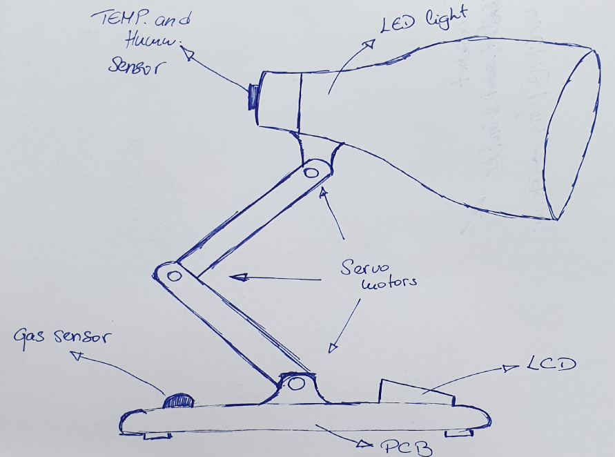
The idea of lamp was in my head for a long time but allways in clouds, so this is perfect oportunity to realise my idea. Ofcours this lamp should be smart to show what I have learned trough the Fabacademy. Now this below is rough sketch of lamp that I would like to make, it shoud be atractive lamp for home use and the smart part of it would include temperature and humidity sensor, methan gas sensor, LCD to track environment status and ofcourse LED ring to light up the space. For material, I would like to use plywood, plexiglass, printed PLA and silicon from molding.
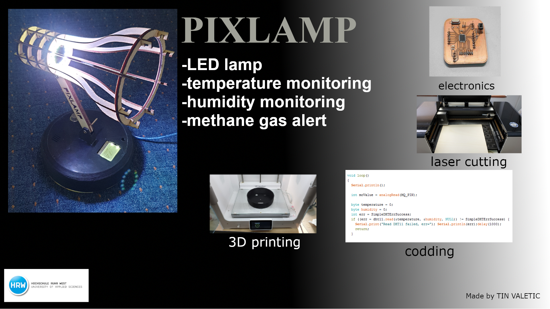
PIXLAMP
This is the page where I'll describe the workflow for my final project. As you can see above is sketch of my idea. Unfortunately some parts didn't go as planed but afterall it came great.
For the making of this lamp I needed some of the materials and I'll listed them belowe so if someone wishes to mak one of them they can easy see the BOM (Bill of Materials).
BOM
| NAME | PRICE |
|---|---|
| PCB components and sensors | 27,86 € |
| Acrylic(plexiglass) and Plywood | 8 € |
| Filament for 3Dprinting | 5,8 € |
| TOTAL | 41,66 € |
3D PRINTING AND LASER CUTTING
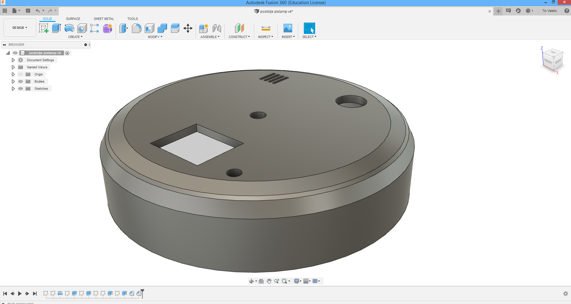
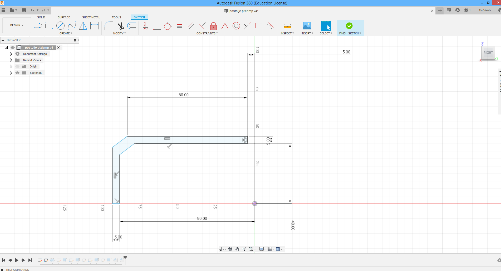
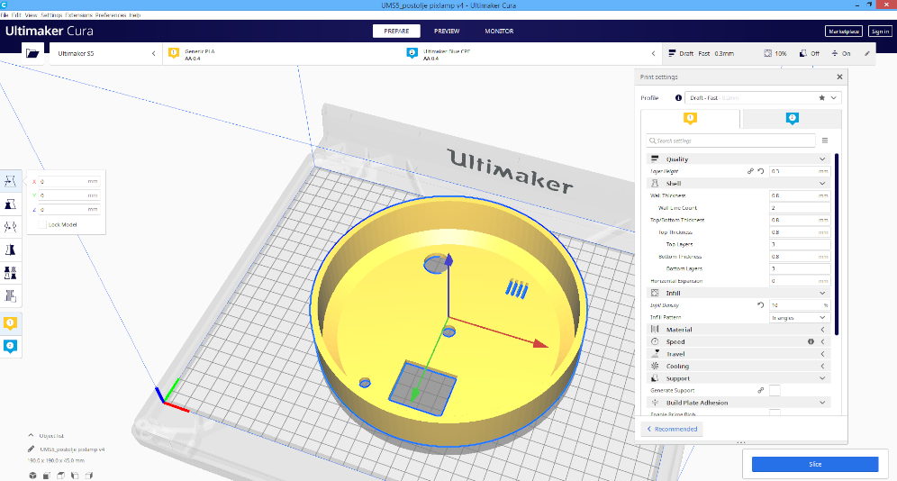
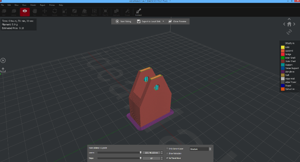
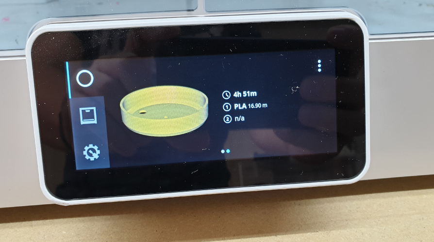
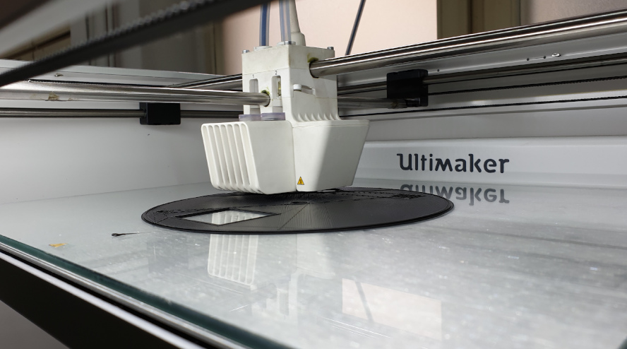
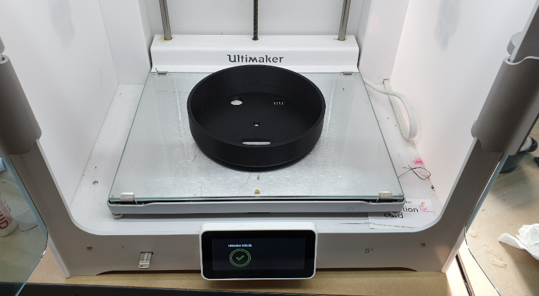
First on the list to do for the lamp is to use CAD software to model a base for the lamp that is going to be 3D printed. This is the part where I had a lot of trouble with printing. The problem was in overhanging, I didn't put any support to hold thet part so the edges started to warp after some 2-3cm of printing, bezause the build plate was hot and the heat from it was causing the warping so the printer was showing all the time eror that the filament is not coming out of the nozle. After couple of attempts to resume the prining, the model stoped to warp and the printer was abble to finish the model. The lession for the next time is to use support or to put smaler overhang of the model.
Here are some pictures of preparation in the Fusion 360 for printing. In the begining the model was taller, but I resize it because of time and material consumption. And after all I agreed that that was good call because all components feated in the base of the lamp. Also below are pictures from Cura (Ultimaker software) and finished print.
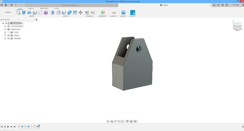
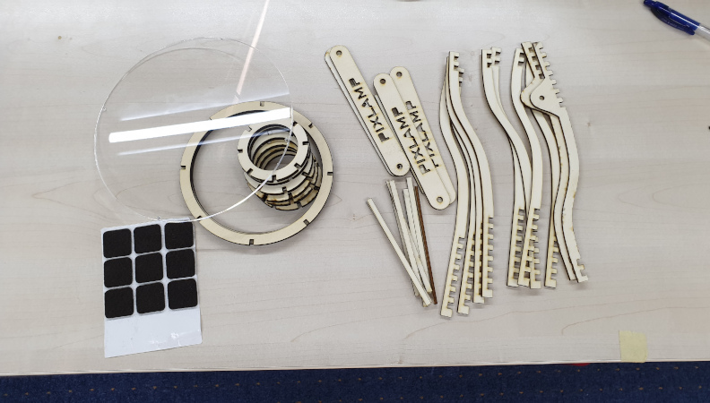
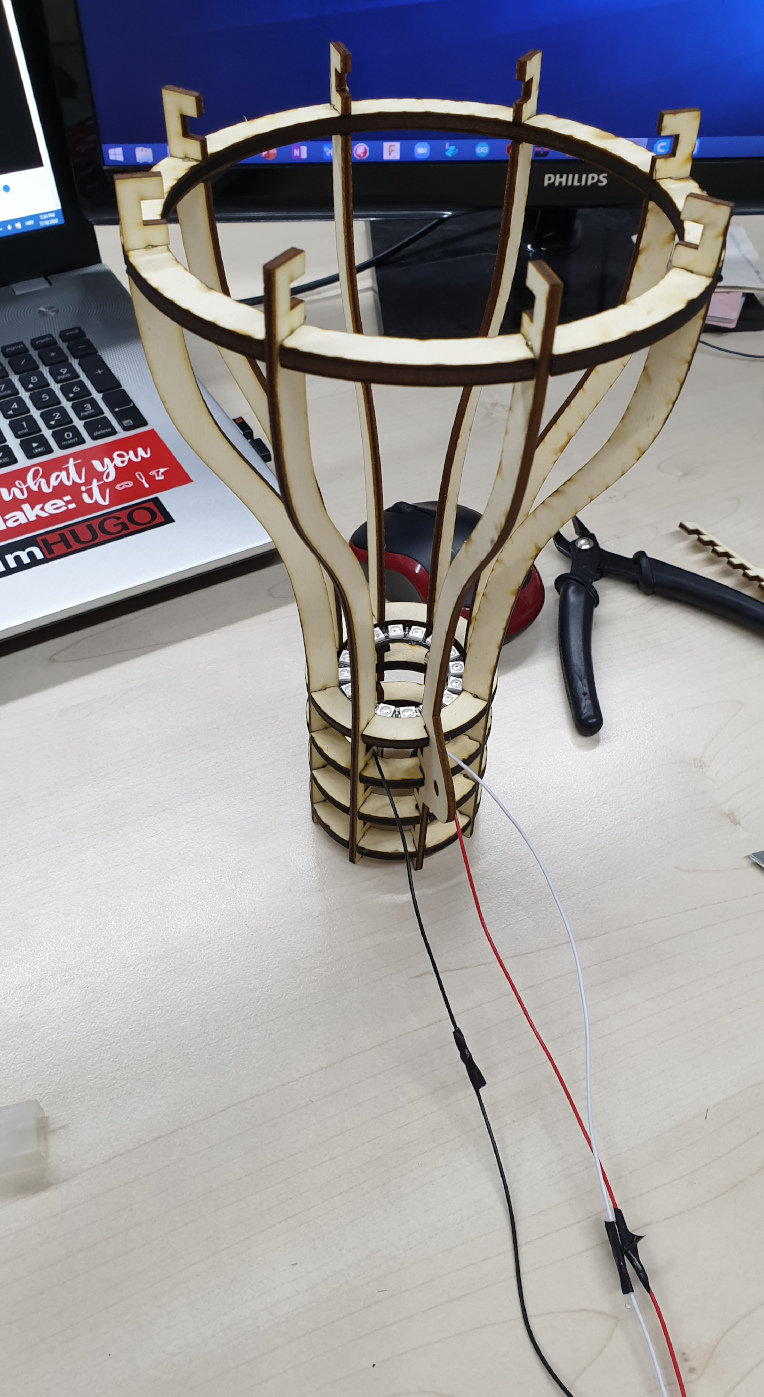
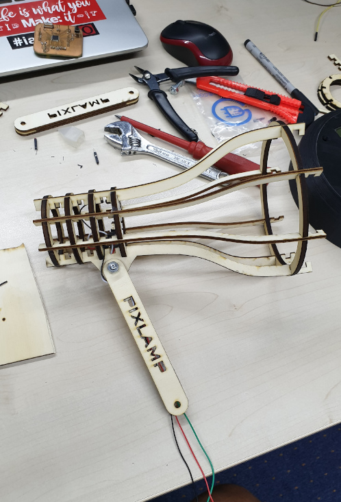
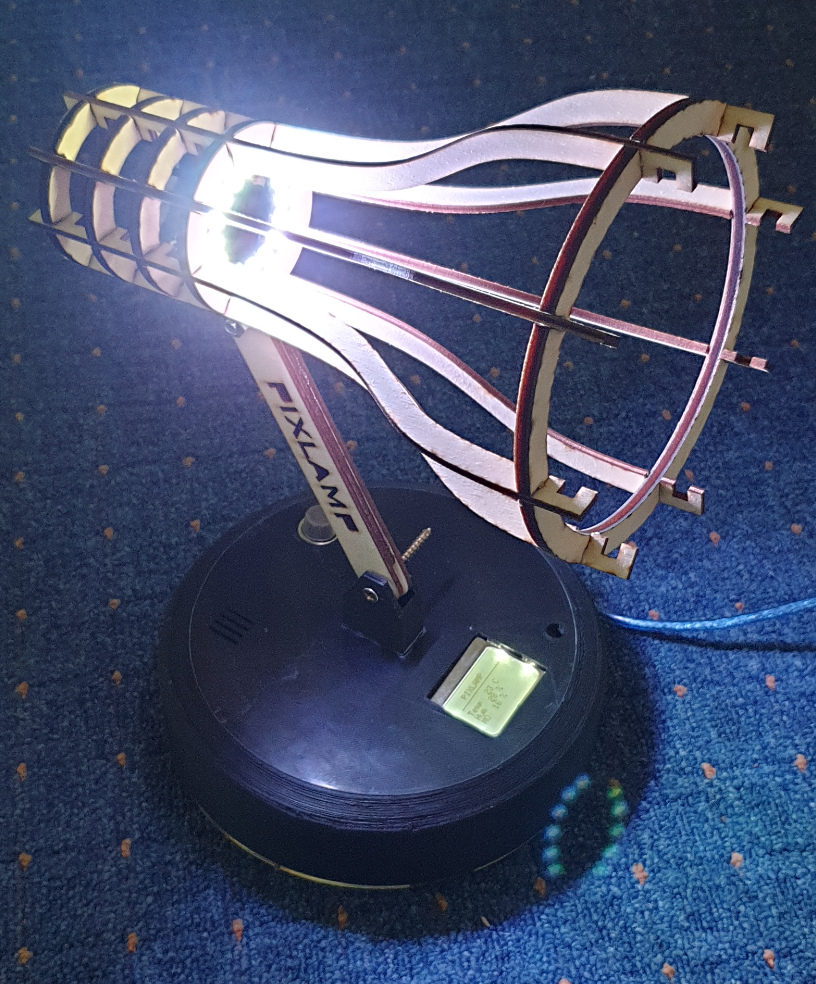
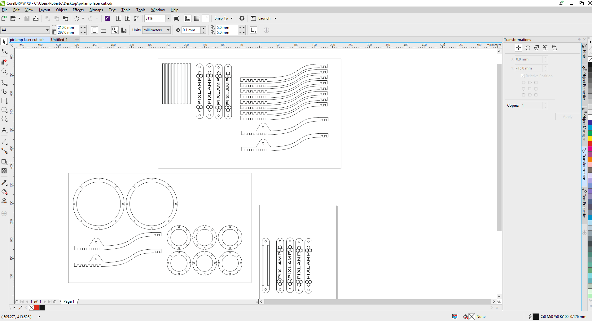
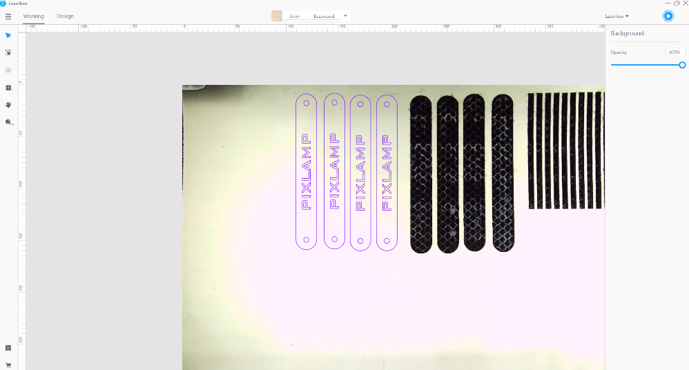
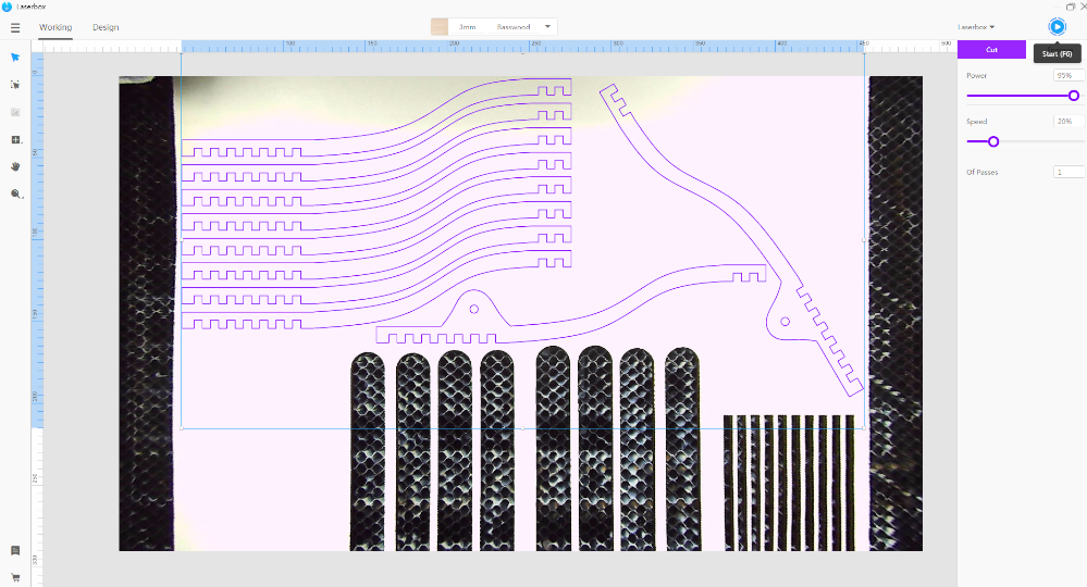
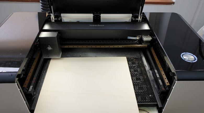
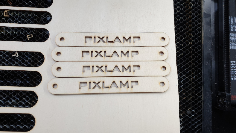
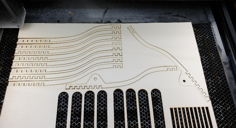
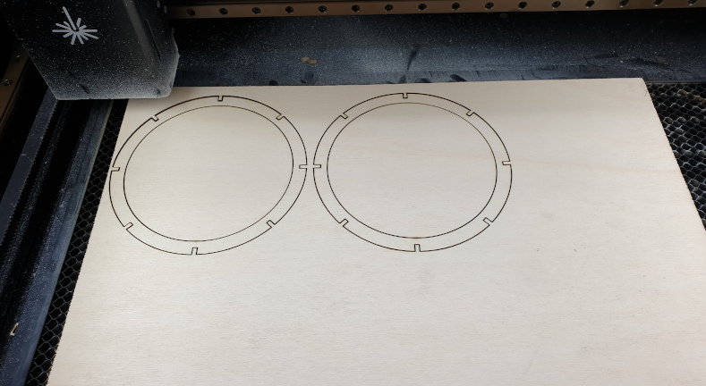
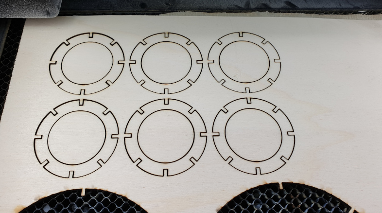
While the printer was printing the stand and the housing, I prepared all needed files for laser cutting and went to cut my other stand and housing for LEDs. The idea was to have some cool design for the lamp and I think it's ok with the coolnest, it could be better but that's going to be better on the upgarded version.
For the 2D design for lasercutting I was using CorelDraw softwar and after finishing needed to export it to .dxf file so the laser could read it. In lasercutting I had no problems...mostly people have problems with aming for right speed and power to cut the material, but I had luck because I was using smart lasercutter that can detect material and he adjust the power and the speed by himselfe.
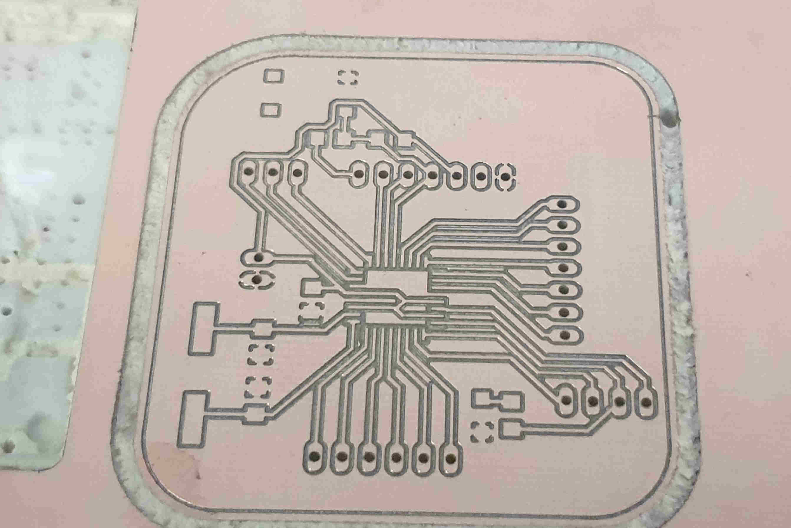
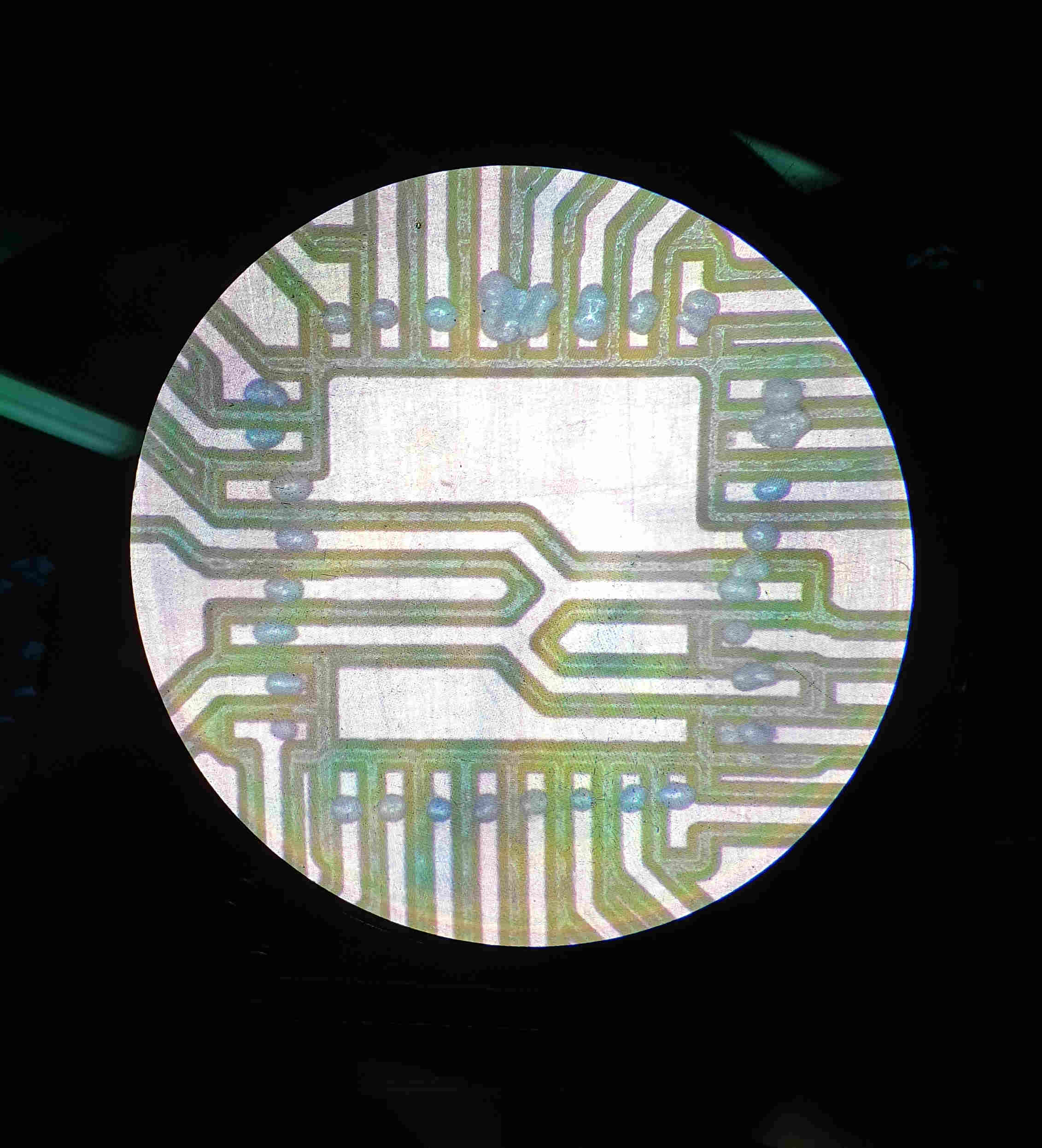
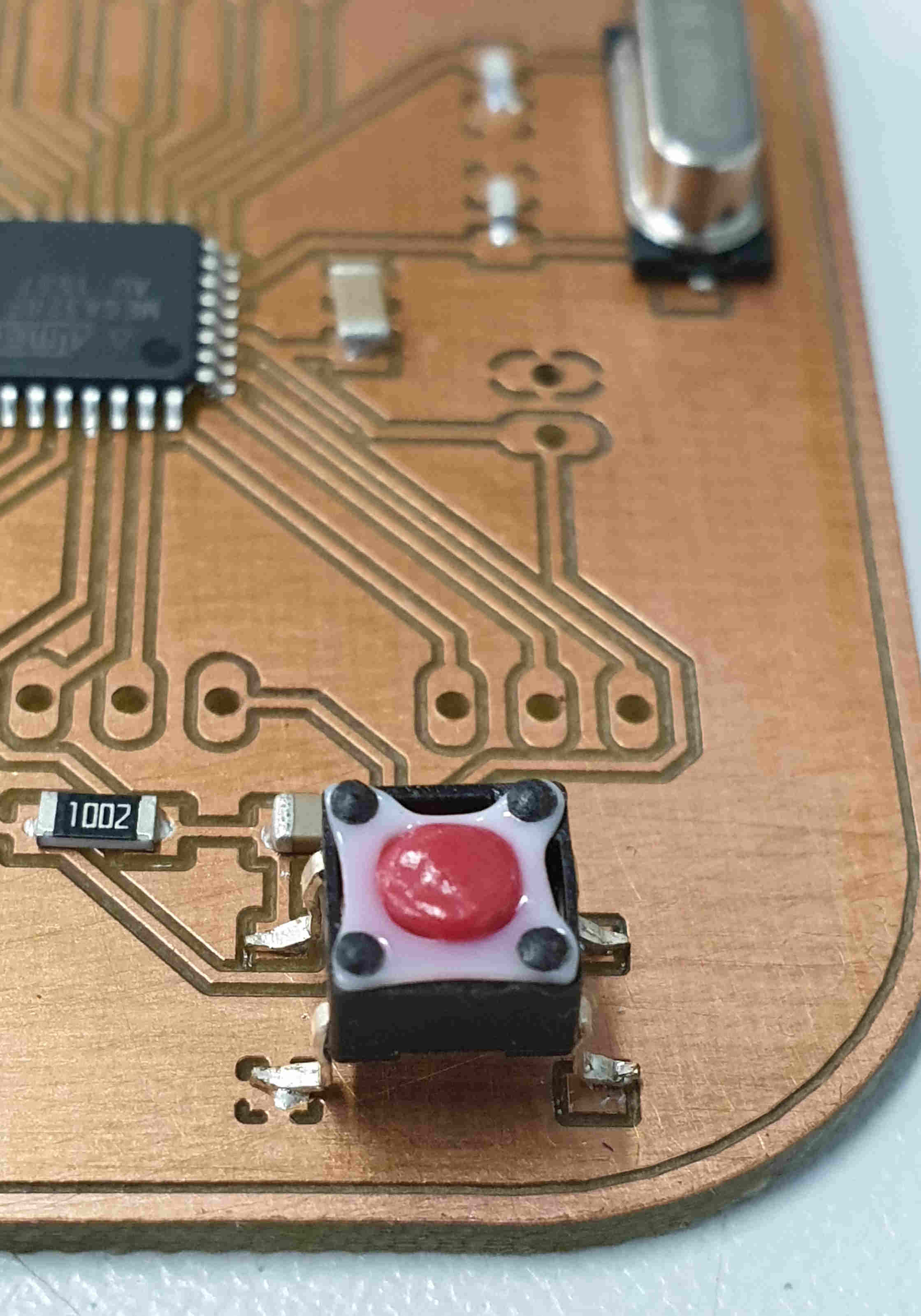
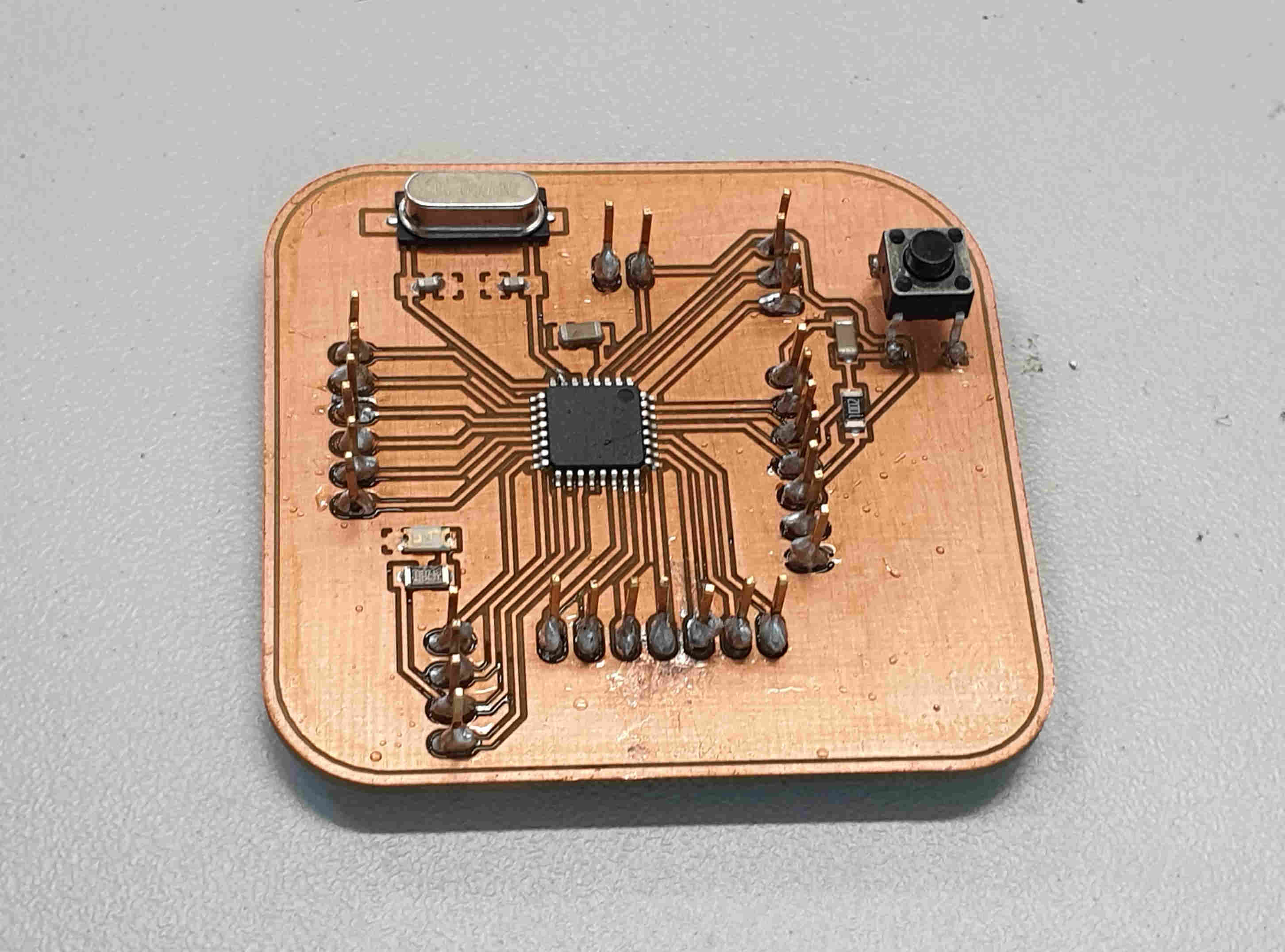
PCB PREPARATION
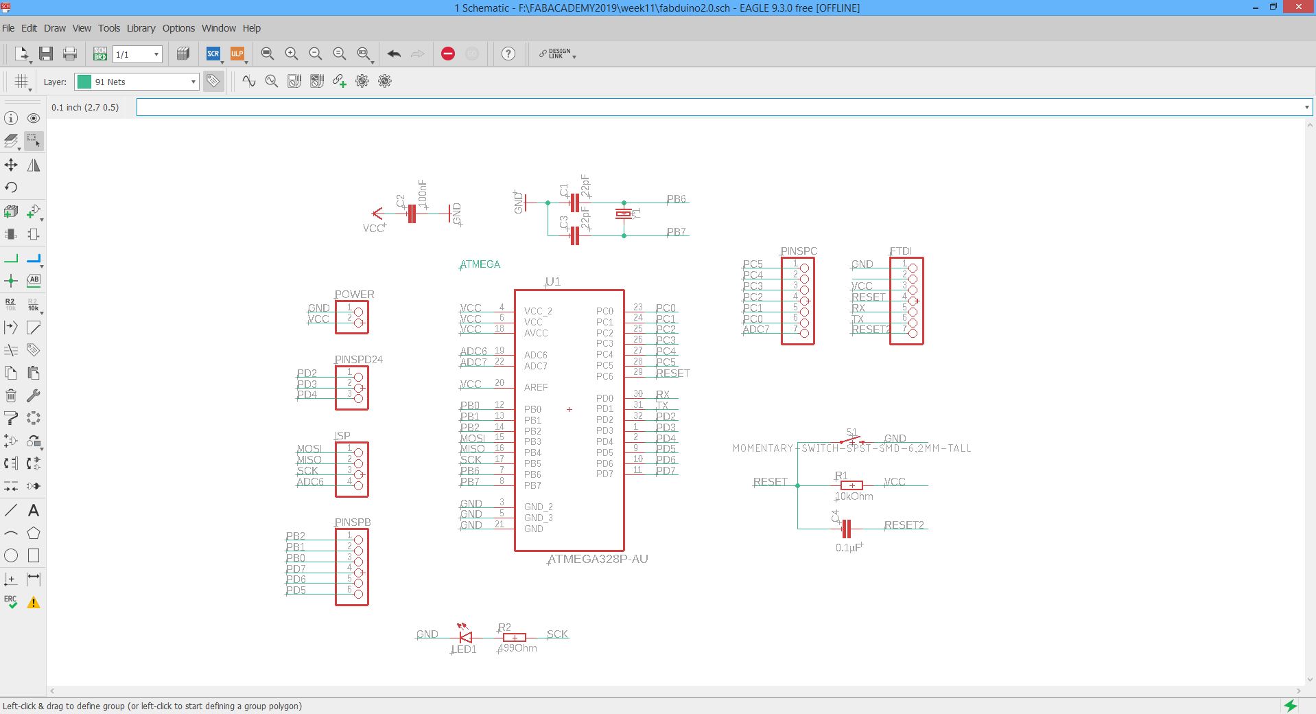
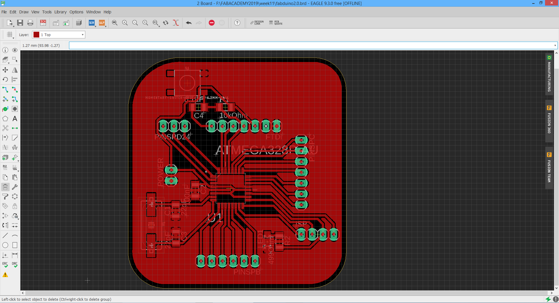
For PCB design I used Eagle software like in my preaviuos tasks. PCB preparation proces also went smoothly, only I forgot that the button is not suposte to go in the oven because it is going to melt and that's actualy what happened, but I changed it for the new one. This is the PCB design that I made in the INPUT DEVICES week, I'm using it for my final project because it is good enugh for the sensors and tasks that I need. So below you can see pictures from that proces, from Eagle to the finished board. After the board is finished the one step is left to do and that is to connect it to computer and in Arduino IDE run "burn bootloader" and now the board is prepared to be programed.
But first the list of all needed components.
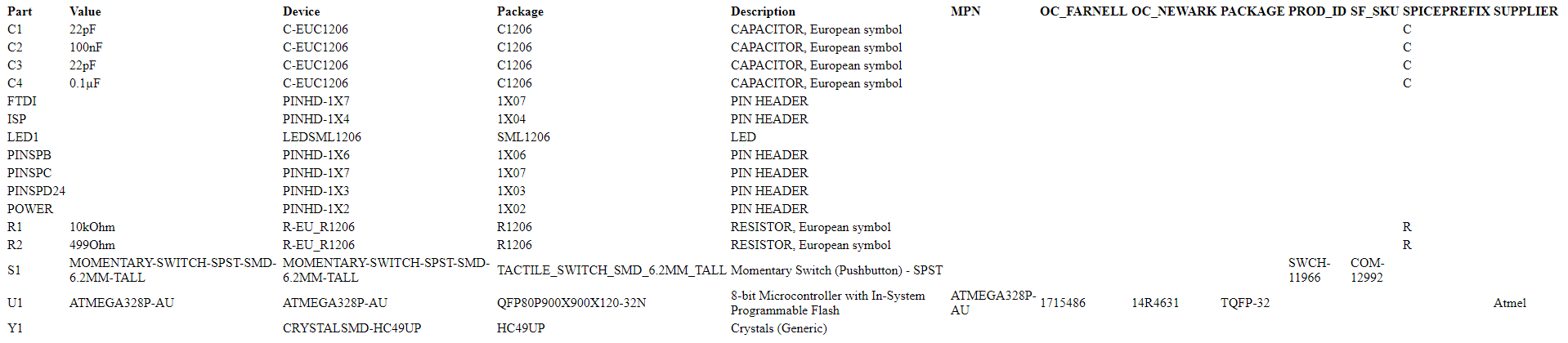
And now all the steps :)
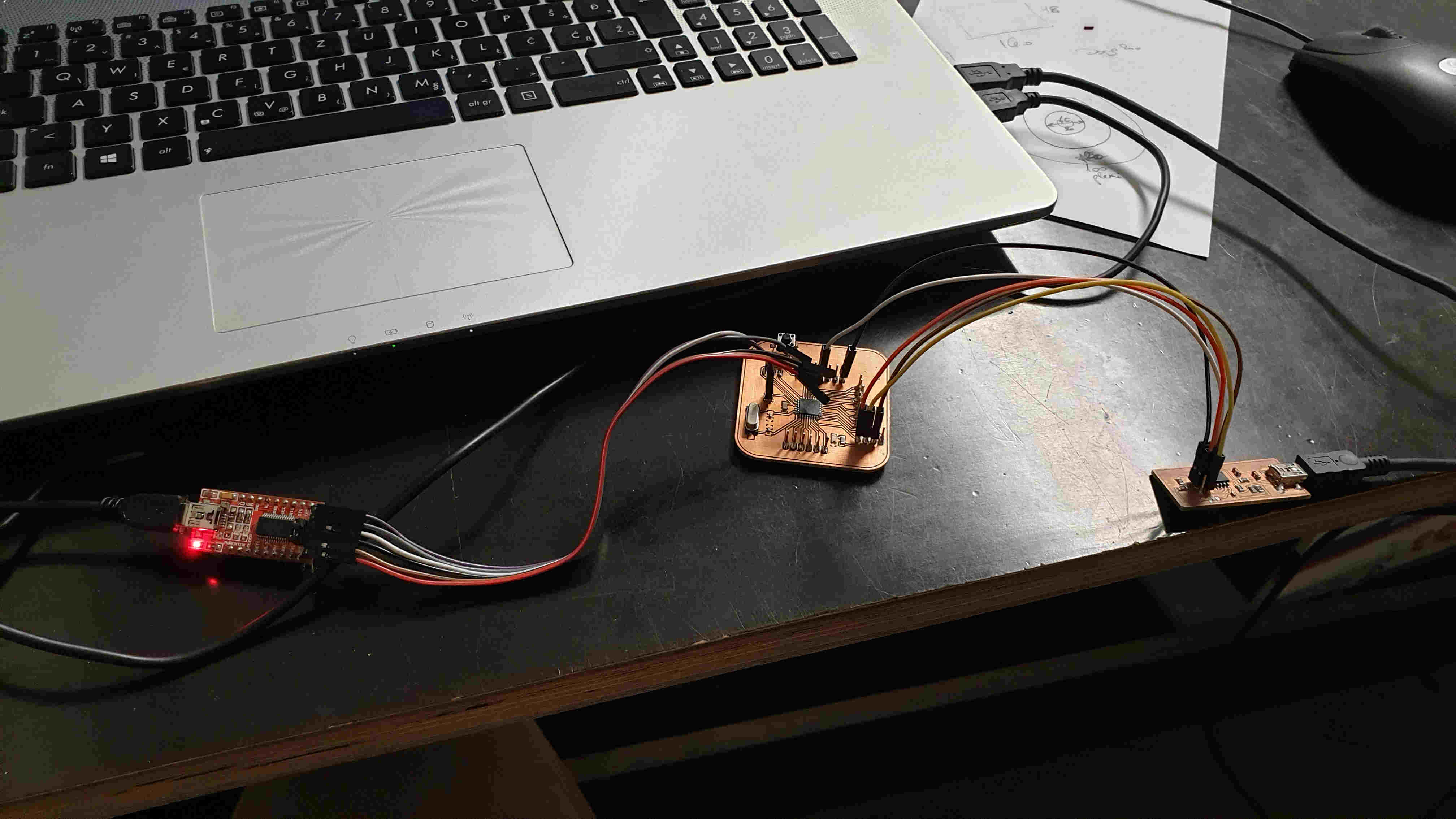
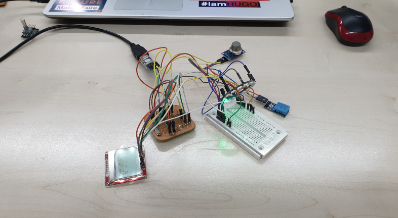
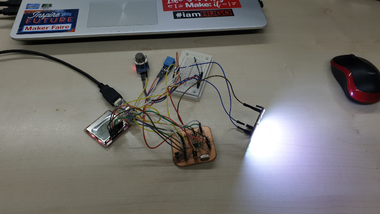
CODDING AND TESTING
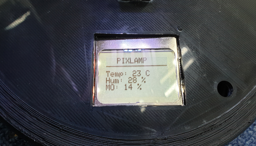
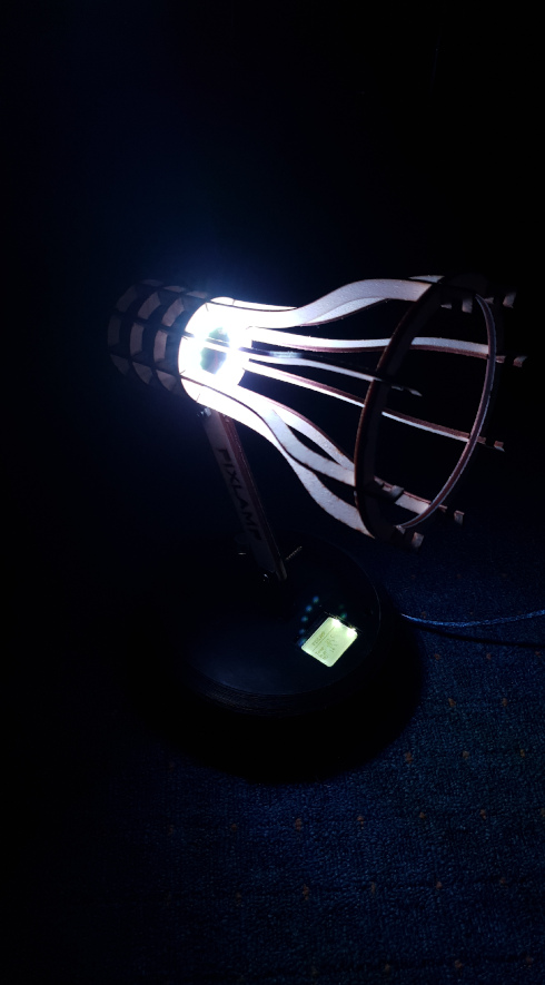
Before the final assambley there is need to program the board first and to check is everything working properly so that I don't have to brake apart the lamp if something is not working. The main goal of the lamp is to monitor environment behavior, temperature, humidity and methan concentration in the air and ofcours that the lamp can light. I wanted to show all the values o the LCD and that the light is white all the time, but when there is too much methan in the air the LED turns red, so as a warning to us because the methan is deadly in to much percentage. In my case I needed to simulate that with the lighter gas can so I could see is the code working or not. Belowe you can see the code that I'm using trough the Arduino IDE and it's working perfectly.
#include <SimpleDHT.h>
#include "FastLED.h"
#include <SPI.h>
#include <Adafruit_GFX.h>
#include <Adafruit_PCD8544.h>

Adafruit_PCD8544 display = Adafruit_PCD8544(5, 4, 3);

#define NUM_LEDS 16
#define DATA_PIN 7

CRGB leds[NUM_LEDS];

#define DHT11PIN 2
SimpleDHT11 dht11(DHT11PIN);

#define MQ_PIN A0

int i = 1;

void setup() {
  Serial.begin(9600);

  FastLED.addLeds<NEOPIXEL, DATA_PIN>(leds, NUM_LEDS);
  pinMode(MQ_PIN, INPUT);
  leds[0] = CRGB::White;
  FastLED.show();

  display.begin();
  display.setContrast(60);
  display.clearDisplay();
}

void loop()
{
  Serial.println();

  int moValue = analogRead(MQ_PIN);

  byte temperature = 0;
  byte humidity = 0;
  int err = SimpleDHTErrSuccess;
  if ((err = dht11.read(&temperature, &humidity, NULL)) != SimpleDHTErrSuccess) {
    Serial.print("Read DHT11 failed, err="); Serial.println(err);delay(1000);
    return;
  }

  Serial.print((int)temperature); Serial.print(" *C, ");
  Serial.print((int)humidity); Serial.println(" H");

  Serial.print("MO ");
  Serial.println(moValue);

  display.clearDisplay();
  display.setTextSize(1);
  display.setTextColor(BLACK);
  display.setCursor(15, 0);
  display.print("PIXLAMP");
  display.drawFastHLine(0,10,83,BLACK);
  display.print("                  ");
  display.print("Temp: ");
  display.print((int)temperature);
  display.println(" C");
  display.print("Hum: ");
  display.print((int)humidity);
  display.println(" %");
  display.print("MO: ");
  display.print((int)(((float)moValue / 1024.0) * 100));
  display.println(" %");
  display.display();
  delay(500);

  if(moValue > 302) {
    for(int j = 0; j < 16; j++) {
      leds[j] = CRGB::Red;
    }
  } else {
    if(i < NUM_LEDS) {
      leds[i] = CRGB::White;

    } else {
      leds[0] = CRGB::White;

      i = 0;
    }
  }

  i++;

  FastLED.show(); // apply the function on led strip
}
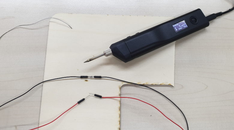
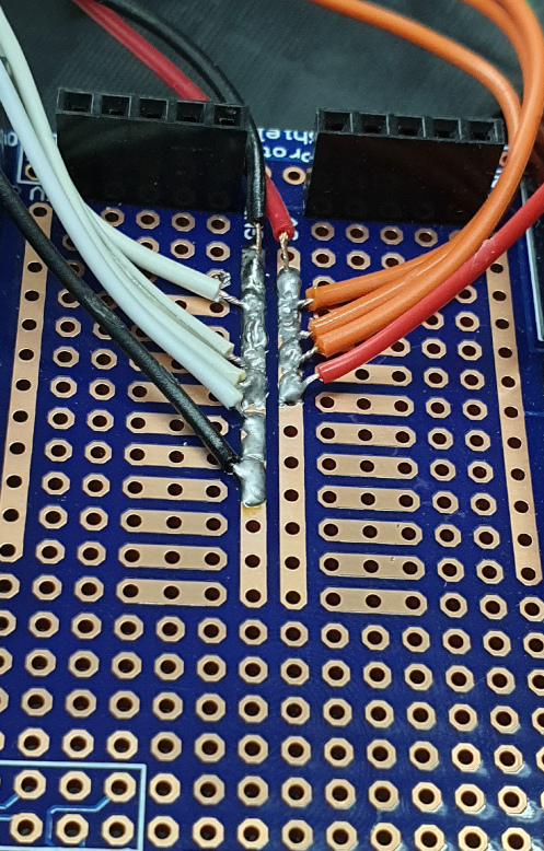
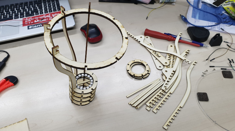
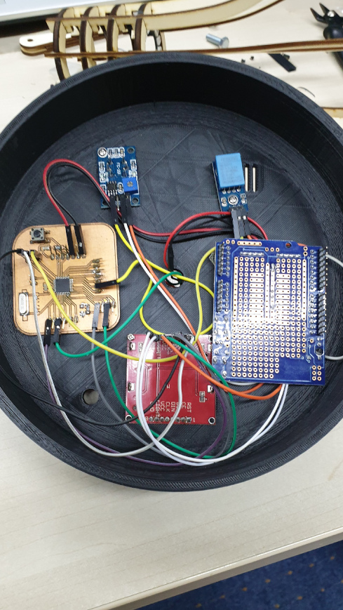
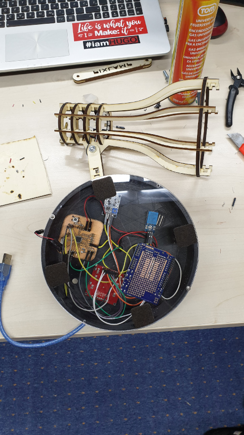
ASSEMBLING
After testing the code, my project is ready to be assembled, but first I need to get reed of the bread board and I'll use the board that I found in my FabLab for the power, just to use it to branch ground and power wires for my sensors. And afetr that is going most trickiest part of this project, assembling everything.