COMPUTER CONTROLLED CUTTING
4.WEEK
In 4th Week I have to work with laser cutter and vinyl cutter, this is also the first week with the group assignment
*This notes were added after the Global review from my global instructor Santi*
Unfortunately I can't add the webpage for the lasercutter that I used for this week because he was ordered over Amazon (I think), but I'll put the webpage from the lasercutter that I used for my final project, it is LASERBOX, on this page you can find everithing for that lasercutter from specifications to what's in the box when you order it. Laserbox is a smart lasercutter who has camera that can recognize it's materials which has the QR code and the camera is from a lot of help because you can easily adjust the drawing to the area that you want to cut or engrave. Makeblock company has amazing support on ti's webpage for this lasercutter, it even has all needed videos for the service so you don't have to call them or shipp the unit for service.
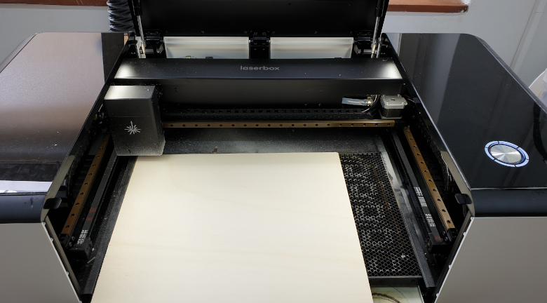
Software for the Laserbox is great to use and you can download it also from the link abowe. He supports vector files and also images and automaticly convert them and pripare them for the engraving.
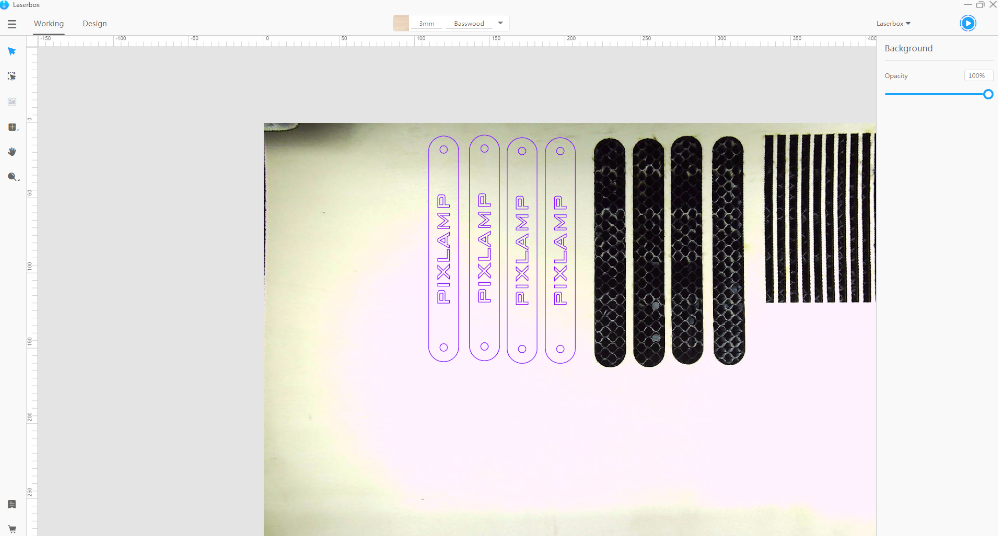
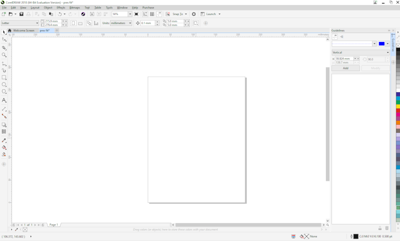
In the picture below I put the one from my Final Project week, drawing is purple because it is set to cut and if we want to change it for example to engraving, we only need to pres the drawing or parts of drawing that we want to engrave and on the right side of the window there is command engrave where we can also set the speed and the power. Blue play button in right up corner is the button to confirm our job and send it to the lasercutter. Middle top command is for selecting the materials and it's thicknes, in that command we can also save our own setting of the material and power and speed for it so for the next time we just sellect that saved material.
This program is also offering us the option to draw our own creation if we didn't do the same in some previous program and it's great for some non complicated drawings like texts and basic shapes.
In comparison with some of the lasercutters this one has fixed Z axis which is 25mm and to cut or engrave I only needed to change the speed and power. For example, on plywood 3mm, I used speed 14% and the power 100% for cutting and for the engraving I used power 30% and speed 100%.
GROUP ASSIGNMENT
To test my laser, first I had to know what it’s capable of and how to use basic commands. On this assignment I was working from my FabLab in Zagreb, Croatia. There we are using SL-1060 CO2 laser cutter with power of 100W and it’s different from one in FabLab HRW, Bottrop, where is Zing CO2 with power of 50w. So I hade privilege to use both and been able to compare some basics beside power. Laser in ZG is bit bigger in all dimensions 600mm x 1000mm and his software I found easier to use than ones from HRWs laser.
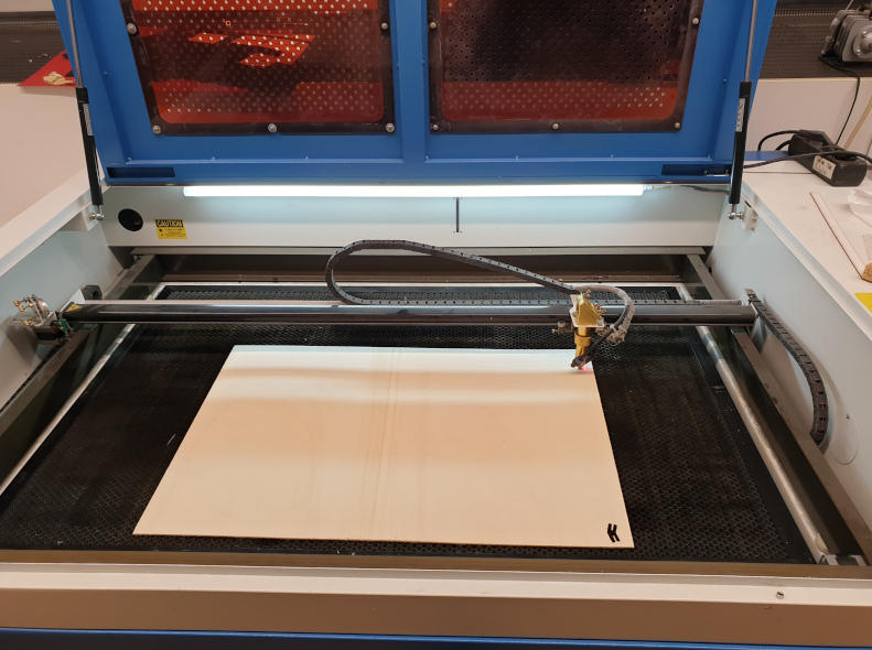
So for the first group assignment I decided to test how is the distance between laser head and the material going to affect on material, basically I was testing the” Z” axis. I tested that on plexiglass and pappelsperrholz because that was only two materials in my lab at that moment. The power and speed was constant for those materials, I put the speed and power intended for cutting through the material.
Plexiglass
Thicknes=3mm; Power=90%; Speed=5mm/s
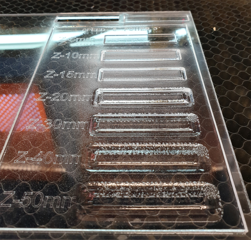
It’s hard to take a good picture from the see through material, but I hope this one is good enough. It can be seen that the thickness of the cutting line(laser beam) is expanding every time I increased high. So for the 5mm distance where is the best focus point for this CO2 laser, it just cut trough the material with the thin laser beam and it was just as expected. For the Z distance of 10mm it can be seen that the focus got wider just a little bit, it was also powerful enough to cut through. But if we work with that distance, we can be sure that our model is not going to be with right dimensions. You can see that the higher is distance from the model, the focus of laser beam got wider, the depth of the cutted part of material is smaller and it’s not cutting but just melting the plexiglass. So maybe in my another tests I will try to bend the plexiglass with the laser cutter.
Pappelsperrholz
Thicknes=3mm; Power=85%; Speed=5mm/s
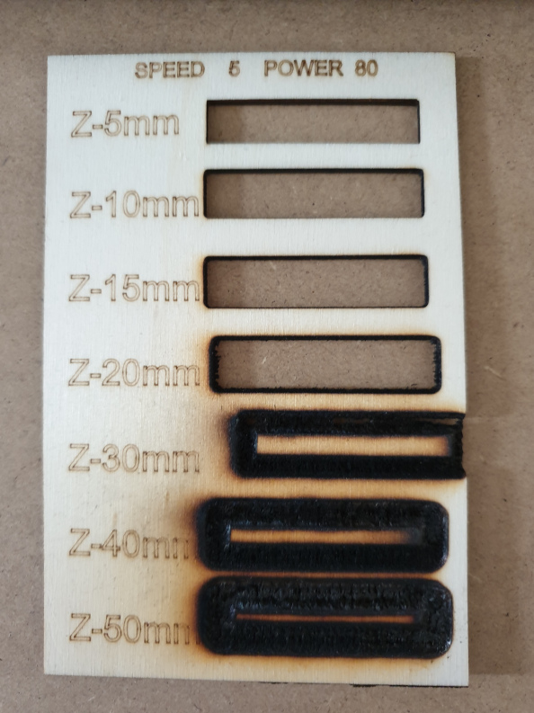
This material reacted on Z distance changes just as I thought...first four tests of distance were cuted all the way through but there is slight difference between dimensions. Because the material starts to burn when the focus is losing and the laser beam gets wider.
Kerf and Settings
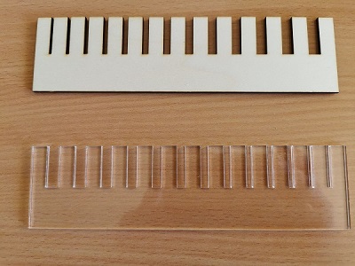
One of the tasks for our group assignment was also to test kerf from our lasercutter. For this week in the end I used three different lasercutters so I decided to test this setings from my favourite lasercutter LASERBOX.
Kerf test was made with the clearence from 1mm to 10mm and to calculate the kerf of Laserbox every clearance after cutting needs to be measured seperately. The vlue of the kerf was 0.11 (0.22/2) and for the plexiglass is the same value.
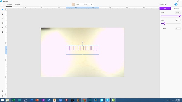
Below are two pictures for kerf test of Laserbox, first is prepared drawing in Laserbox software and on the right side are setings for power and speed. For this model max power(100%) is 40W and the max speed(100%) is 600mm/sec. For this test and also for my final pressfit model on this lasercutter I used settings (power 100% and sped 14%). This lasercutter is a little bit diferent frm the two others that I used because for this one the hight (Z ofset) is automaticall so we don't need to put that value. Abowe, burned playwood is test on the lasercutter wher you can also put the Z value.
Two pictures I borrowed from my good colegue Tatjana Šoronda, thank you :).
PRESSFIT-CONSTRUCTION-KIT
This task was very interesting and I didn’t expect that is going to be slight difficult at the beginning. Because you have to have in mind that the laser beam has its own dimension and it has to be calculated in design.
As you can see my first try was unsuccessful, the joints had to much space between them and the main parts. For modeling the 2D model which is enough for the laser I use Corel Draw, it’s dont hae to be in 3D because the sofware of laser is using .dxf file which is 2D
I had to fix those gaps and send it to the machine again...this time it worked. Joints are just as they have to be, it’s not hard to assemble and disassemble the parts, you can just fill the slight resistance when you do it. And that was the task, to make press fit for which can be assembled without glue.
All work is done in COREL DRAW, my favourite 2D designing software, I am also explaining it in my week 3 (Computer-Aided Design).
So the first was to make one hexagon and one joint, also to make propper gaps so two of them could be connected. Then is command that saved my time more than once, thats command "Possition". Witha that command you can move or multiply objects wherever you want and however you want, so I multiply them just as shown on picture, to fit my sheet of plywood in laser cutter.
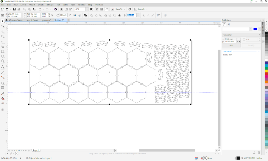
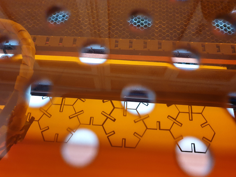
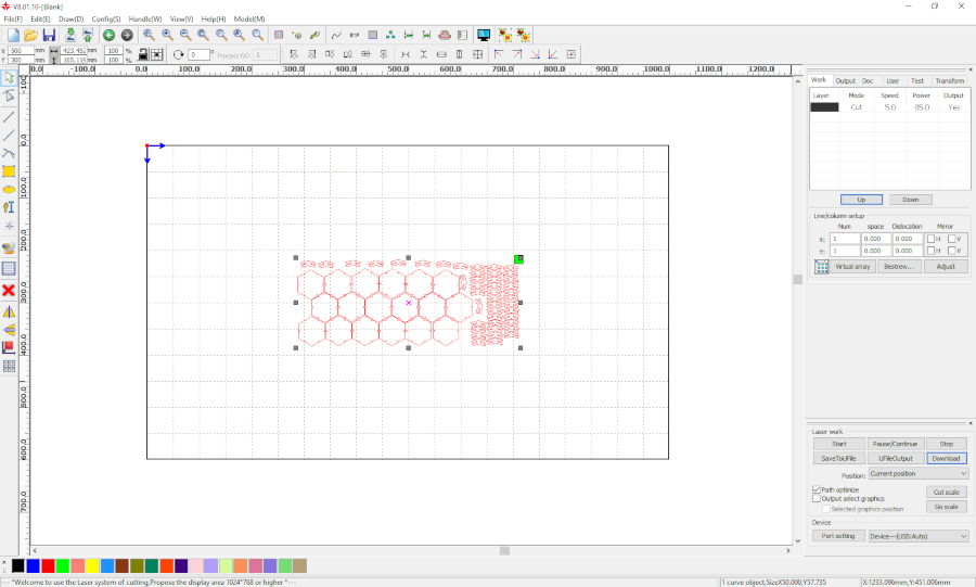
Than the turn was to select all and to send the job to my laser cutter.
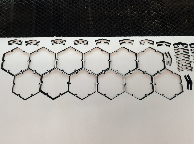
After cutting it's not looking like that, it's a lot nicer. This was the picture when the job was finished, I opend up the lasr cutters dors and remove the sheet and then remember that I need to take a picture so I put all back for picture. In the end resulsts were great, joints were feeting perfectli, yes with little resistance but better like that, then to have gaps betwean parts.
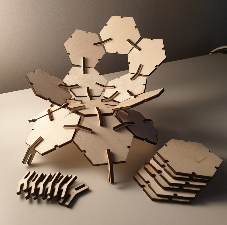
And this is finally my pres-fit example. It tooks me a lot to assamble it and some of joints broke, but after some 30 min I got this.
Parametric design (FUSION 360)
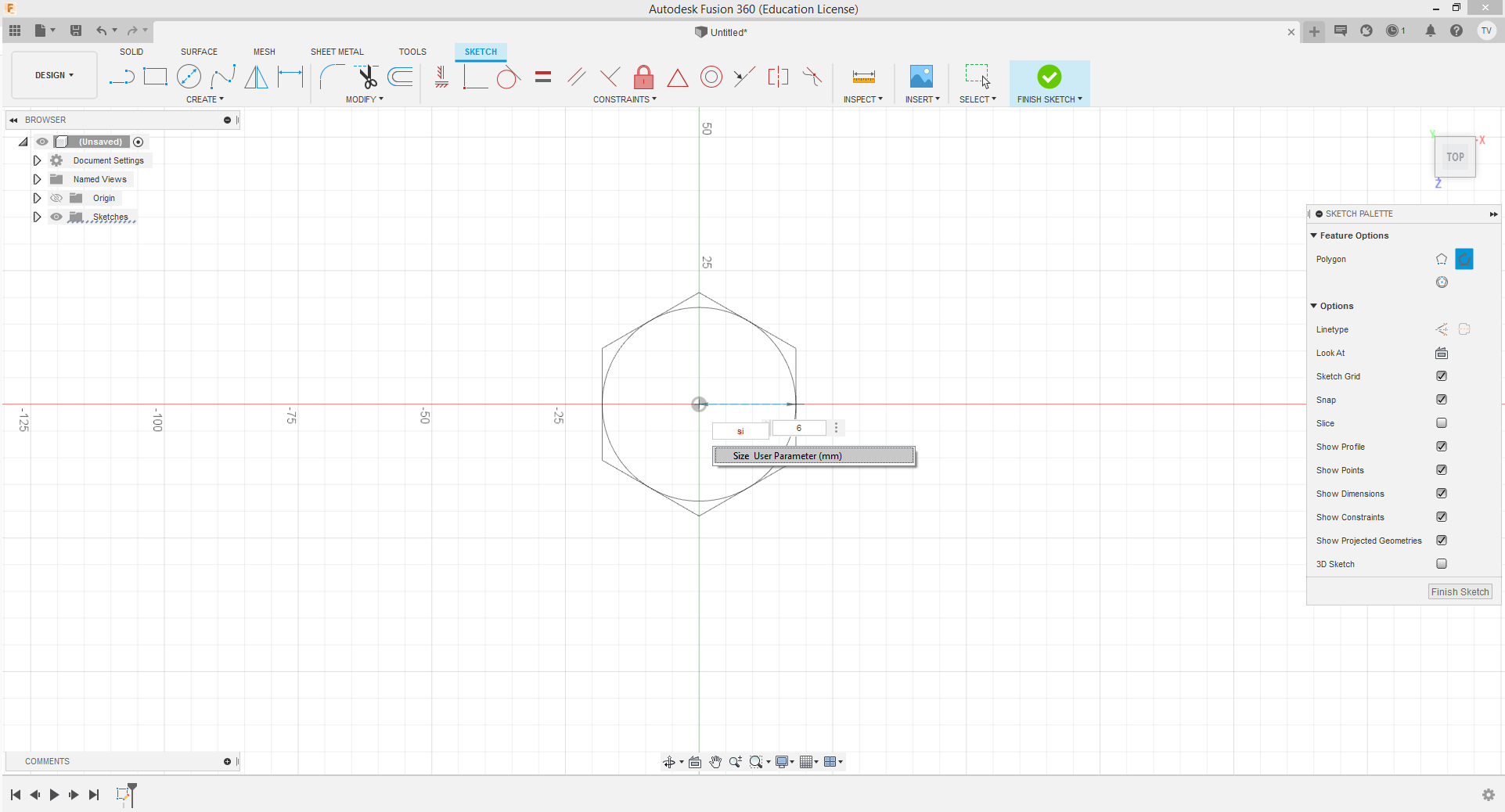
After the work in Corel, my instructor told me that the part of the task was to design the press-fit using parametrical method. In designing the model it means that every dimension/value has to be defined before creating the skatch and every dimension need it's own name so we can easely find it. Now I make the same models but only in Fusion360 using parametrical method and it was really fun and flashback some memories of my highschool when I was working in Catia with the parameters and functions.
There is no big difference between regular modeling with putting dimensions as we work and the parametric method where we can define dimensions before skatching and also paralel with the modeling.
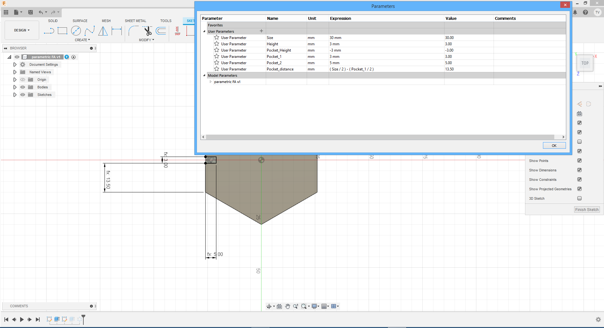
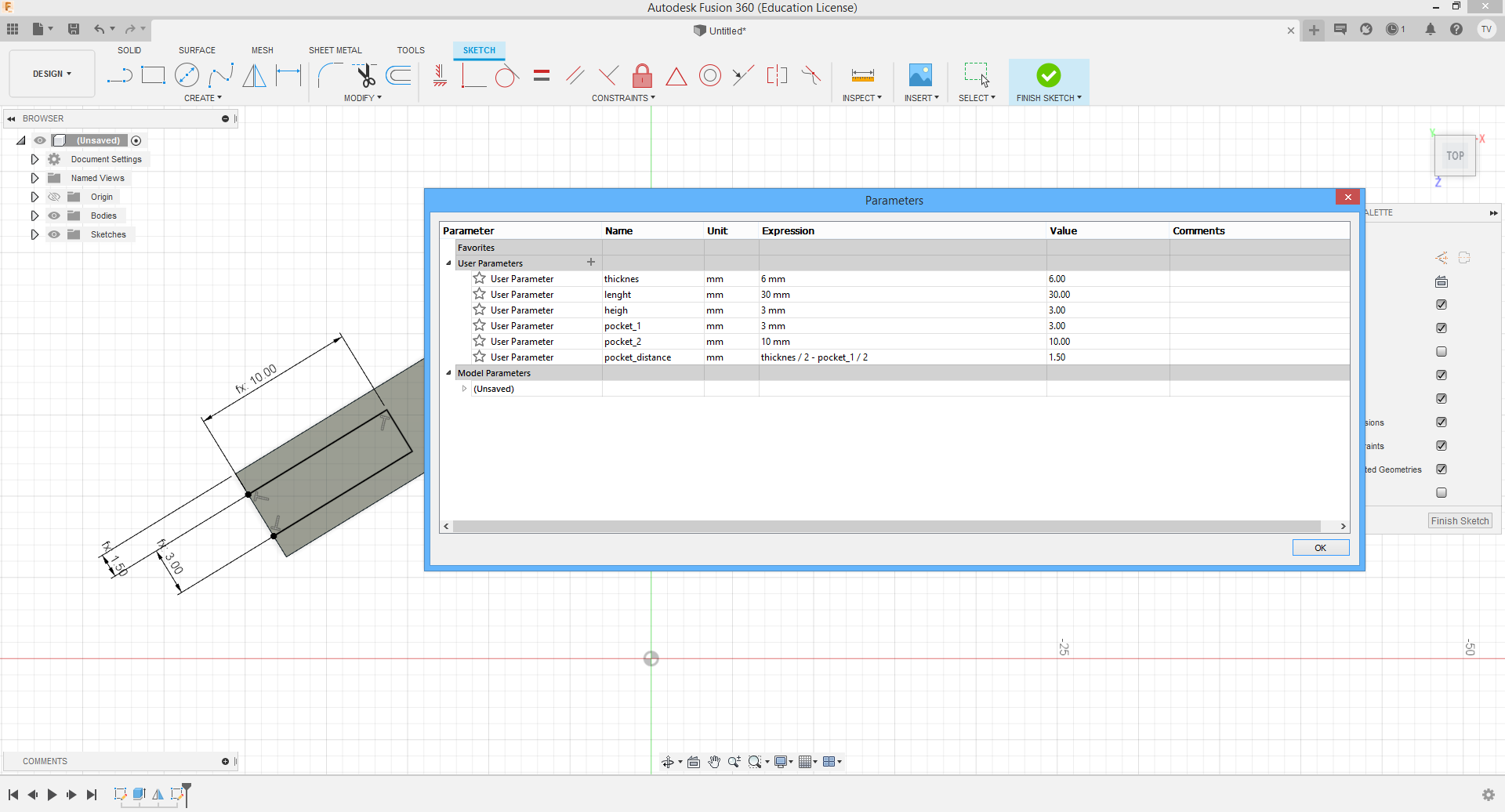
Below is the pop-up window for the parameters where you can add them and it's really easy to do so. I'm also putting all other pictures of the process for the parametric design my model.
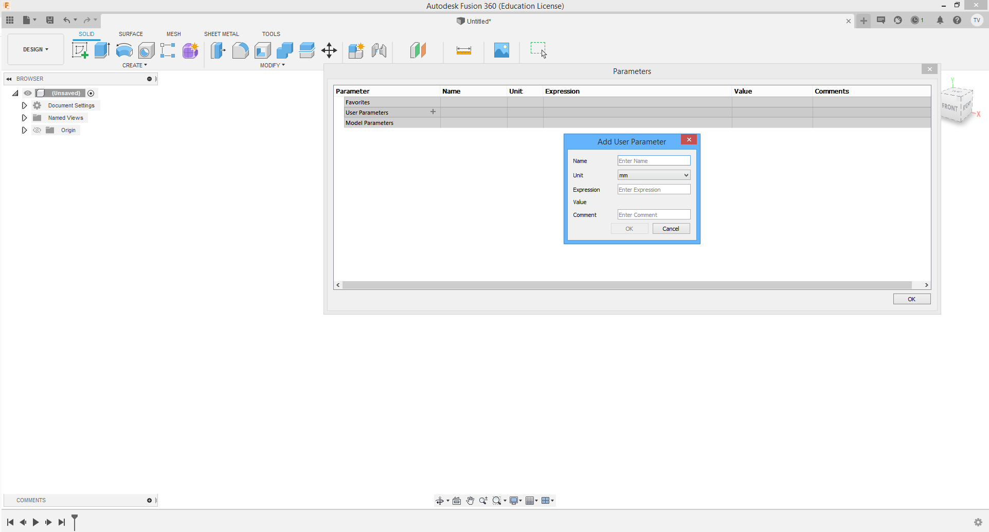
Parmeters pop-up can be found on uper toolbar in "Modify". When we have the paameters that we have, we only need to type it's name when we want to define that dimension as it's shown below.
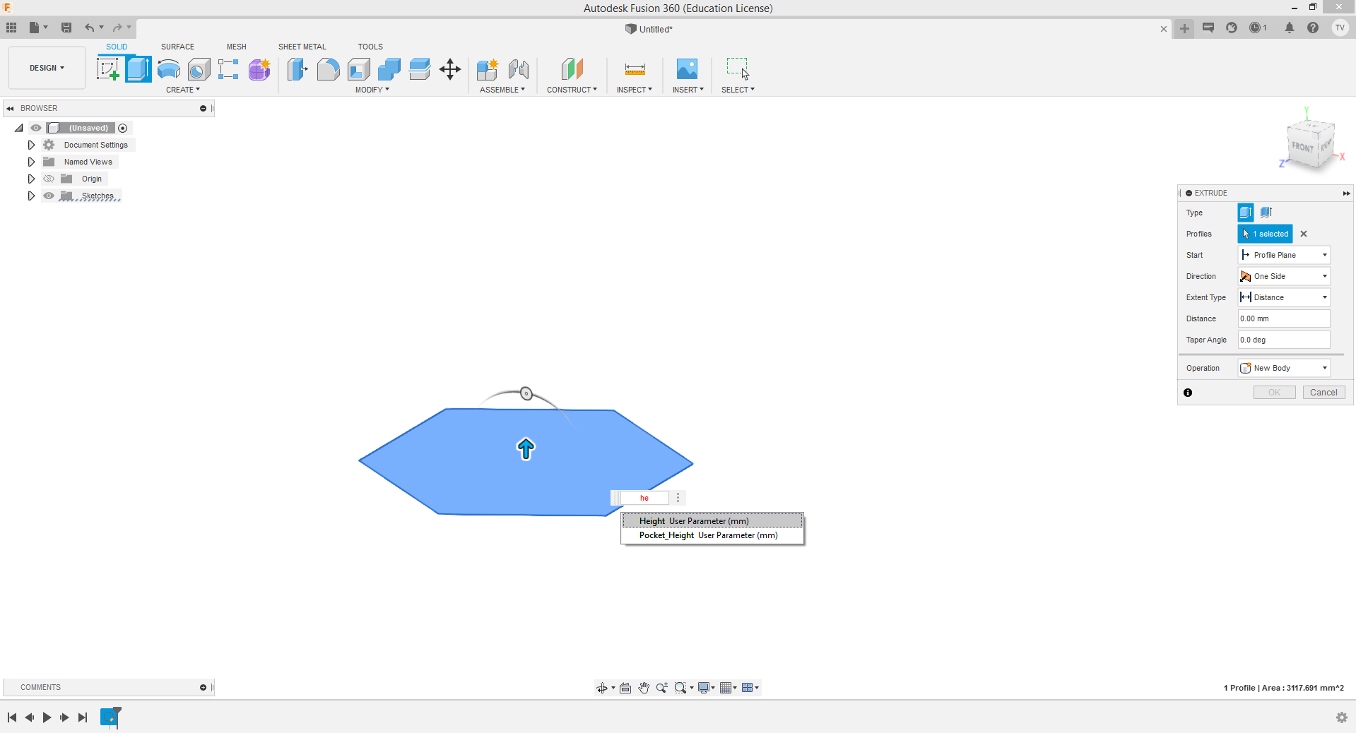
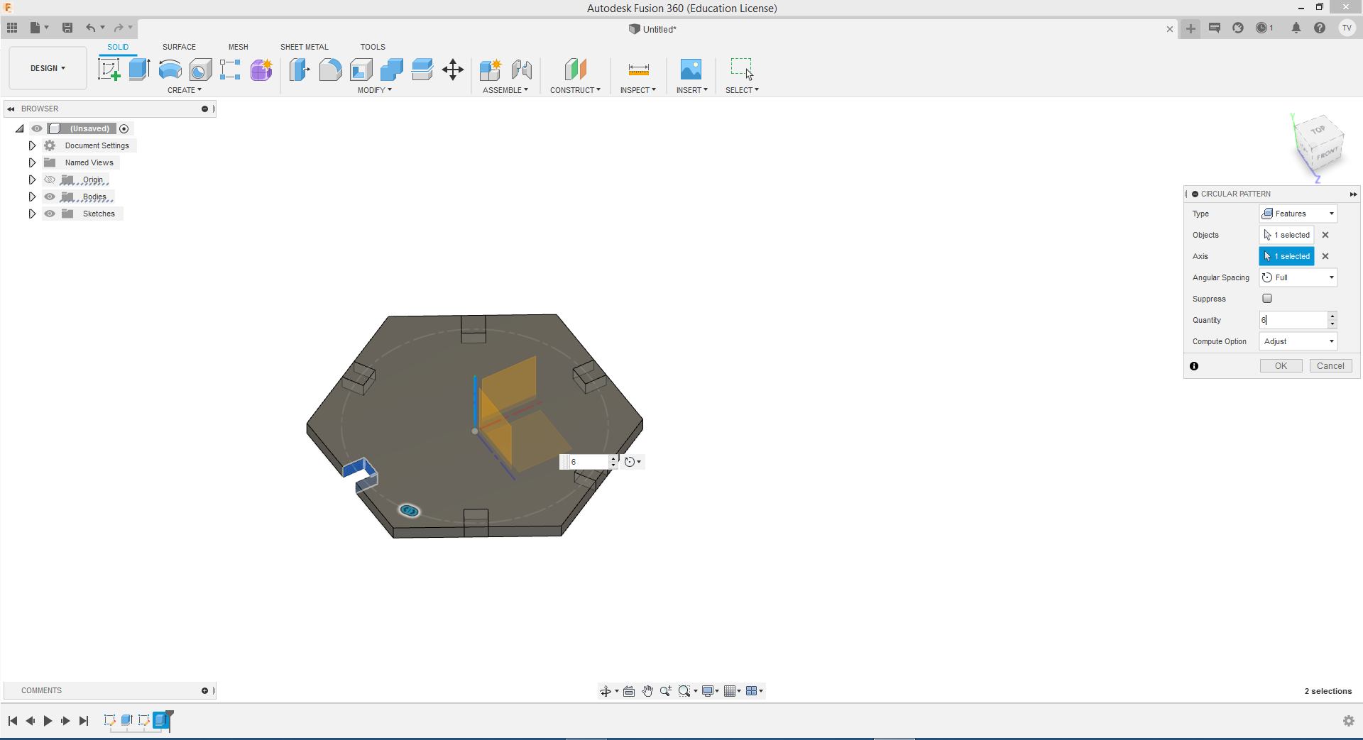
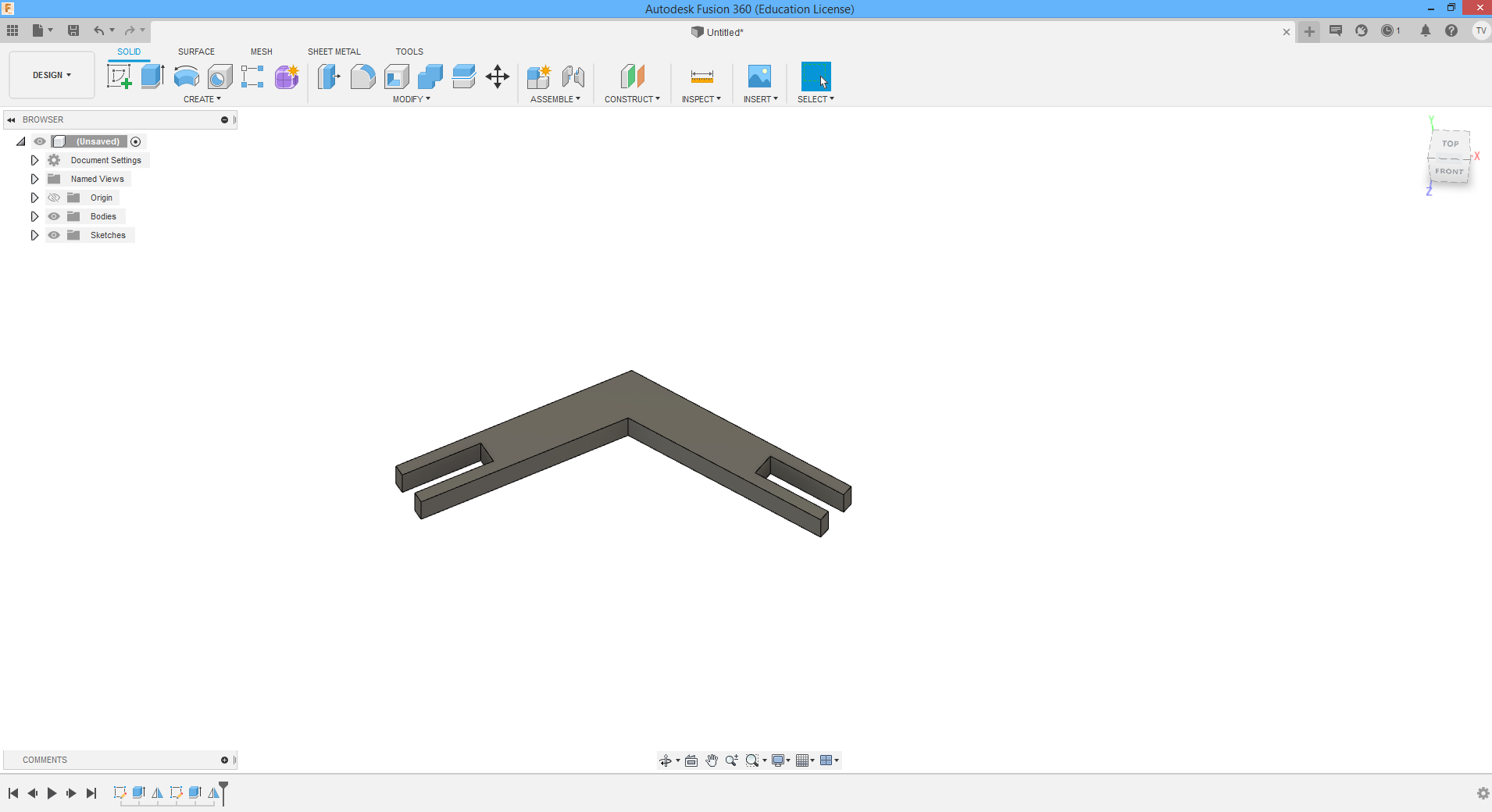
After making the main part of pressfit it was time to make a join, also with the same method.
My conclusion for this part is that this method saves you a lot of time when you are, for example, working on some prototipes and making couple different sized models for which you need to change parametrees all the time all he way to the perfect model.
VINYLCUTTER
Because of my earlier knowledge of vinyl cutter I hope that I’m not going to make some mistakes, but from every mistake we learn something new:)
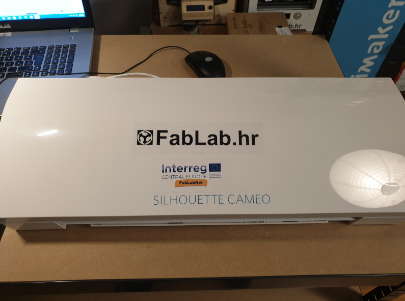
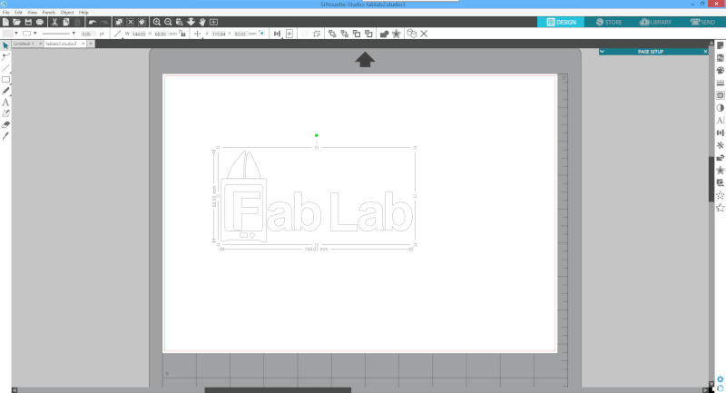
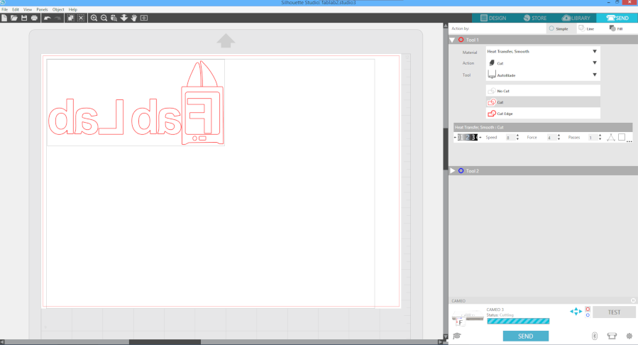
For making the samples for vinyl I also used Corel Draw and the logo around the “F” letter I took from Ultimakers notebook. On first picture it is shown how it looks when it's transported to SILHOUETTE software and after it's checked that everything is alright I need to press in the right corner "SEND". This is the step wher I can chose what I'm going to do wit the material (action), what tool I'll use, what lines of sketch should be involved and if im cutting, what depth is going to be.
Before sending the job it is important to check all parameters, like type of job(cutting, no cutting, cutting only endges), also tool and depth of the tool job, and I think most important is to revere the view depends on material you are using. I'll use termofoil that has to be cutted on side fithout the foil.
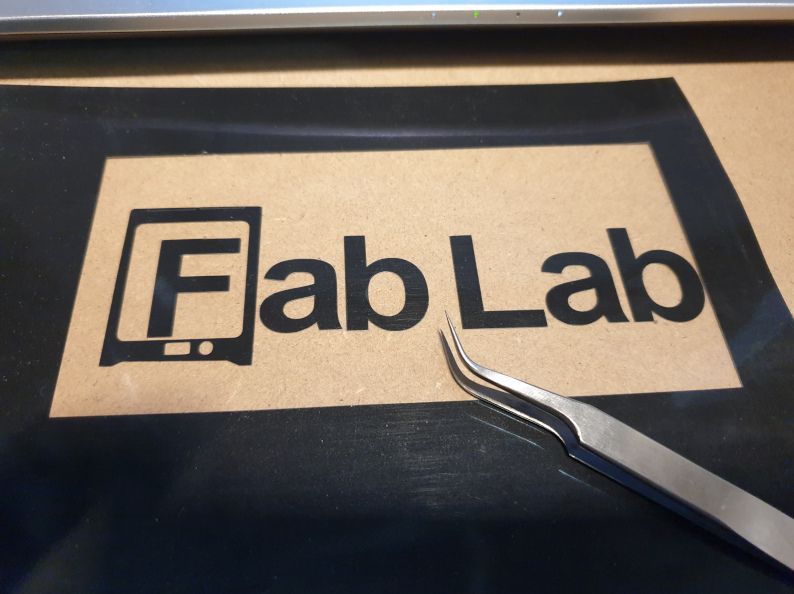
My first attempt was to make that FabLab logo, transfer it to the t-shirt and I succseded, but on the other attempt where I wanted to cut my own logo of tiger, I didn’t manage to do it, because it was to detailed for the cutter and the speed was to high.
After I cutted the termofoil I needed to remove all unwanted parts from the plastic seetrough foil with the twezlers, there is the final job to do in which I’m not so good and that’s ironing the termofoil on the wanted part of clothing. Unfortunately I don’t have a picture of ironing, but I have other pictures…
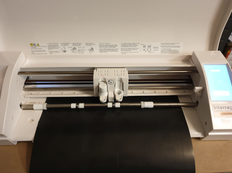
When the cutting if finished, this is how it looks when I turn it over on side with foil, the knife ws cutting the other side. As we can see all lines were cutted fine.
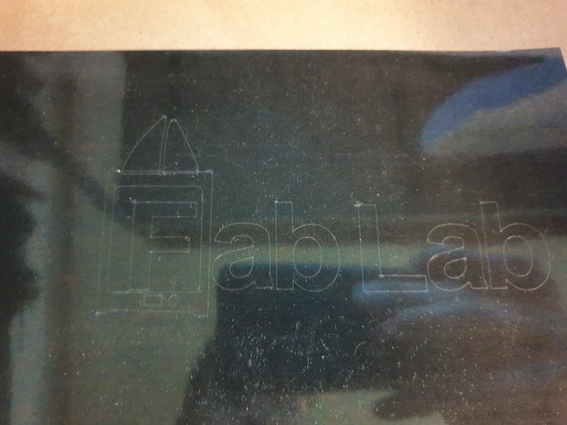
Step with twezler was some fun time for me. I also removed top part of "printer" that was presenting filament tubes, because they were wrong cutted, it was my fault, I didn't put double lines in software. All other parts were good and final resolt after removing unvanted pieces is shown below.
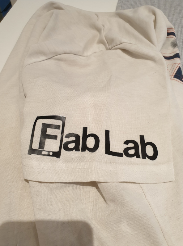
As I mantioned earlier I'm not thta good in ironing so it took me roughtly 20 min to iron this small design...but it worked and the FABLAB stamp is now hard sticked to my t-shirt.
CONCLUSION
The week of Computer-Controlled Cutting was very interesting. I was familiar with the laser cutting and vinyl cutting but just plug and play from the tamplates. This was great task to draw something by myself and than cut it and see the results. It was also great to dive deeper into the proces behind this two machines and their settings. Also hope that in futur I'll work a bit more with this machines and make something complex.