NETWORKING AND COMMUNICATIONS
14.WEEK
INDIVIDUAL ASSIGNMENT
This task I decided to use ESP8266-01 module. It is a Wi-Fi microchip with 32-bit microcontroller capability. he For beginner like me it is good module to start with. But on the beginning I got some small problems that I’ll talk about latter in documentation.
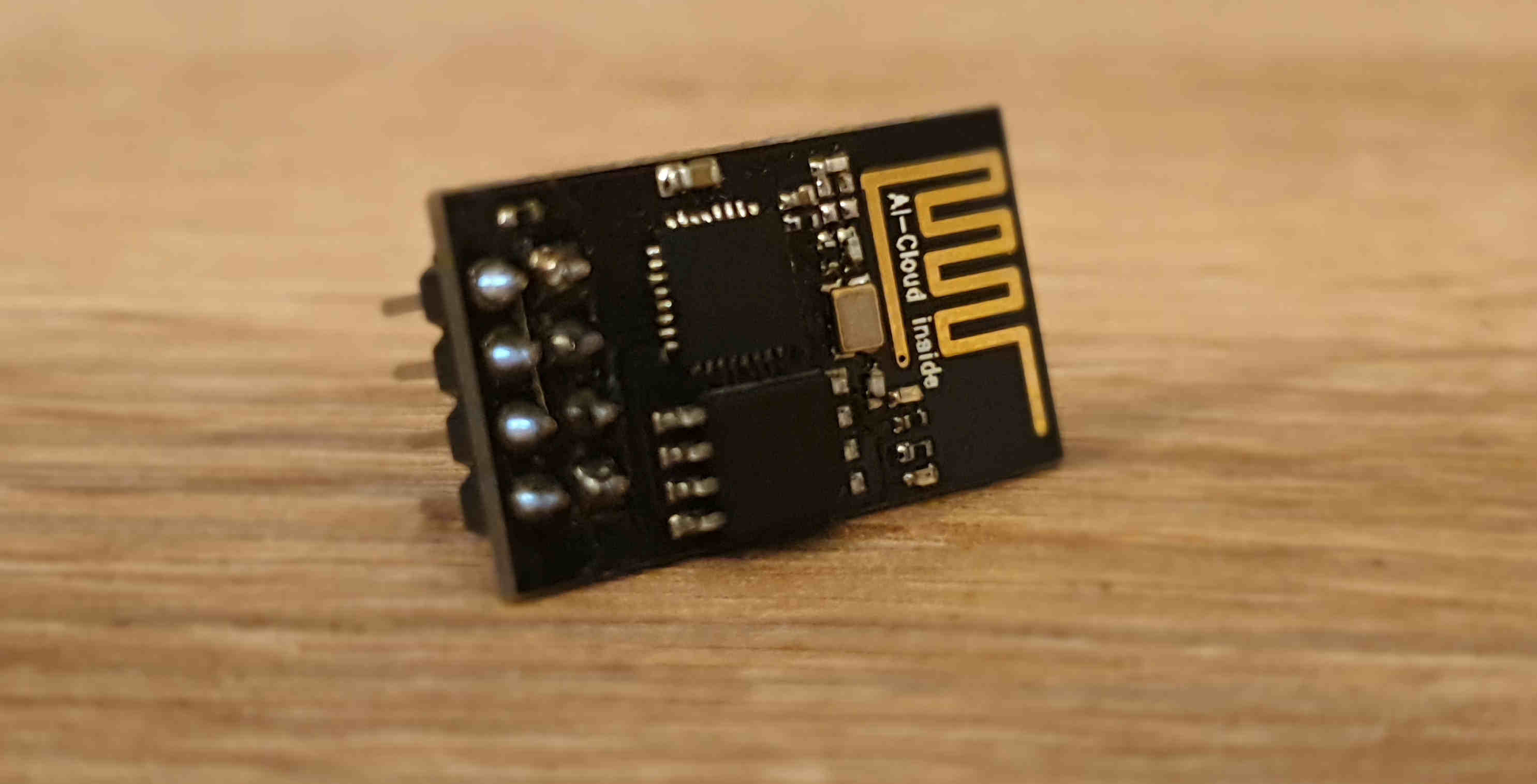
ESP8266-01 is little bit complicated because it does not support 5V, only 3.3V. If you don’t have a Arduino or FTDI with 3.3V pin than you will need to use resistor. The module has at least two different boot modes: ‘normal mode’ and ‘programming mode’. ‘Programming’ or ‘flashing’ refers to uploading any custom or default software or firmware to the ESP8266’s flash memory. Flashing will overwrite the previous programming/firmware (including the AT command set if that was flashed). To be able to flash new firmware onto an ESP-01 module, it needs to be connected to a FTDI.
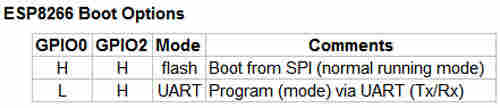
The ESP8266 can either boot up in ‘programming’ mode or in ‘normal’ mode. While booting up, the status of GPIO0 and GPIO2 is seen as input pins (as suppose to output pins) and their voltage status is used to check which mode the ESP8266 needs to enter.
So after little briefing of board I’m ready to try it. First to do is to add in “FILE>PREFERENCES>ADDITIONAL BOARDS MANAGER URLs” this link(http://arduino.esp8266.com/stable/package_esp8266com_index.json), than I need to add the ESP8266 board and I’ll do it by go to “TOOLS>BOARD>BOARDS MANAGER>” and there is search line type ESP8266 and install the package just like on picture below.
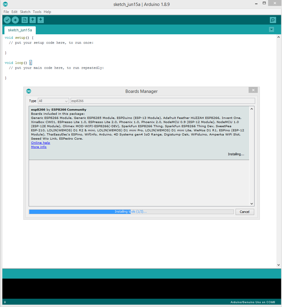
Now when the board is successfully added I’m good to go.
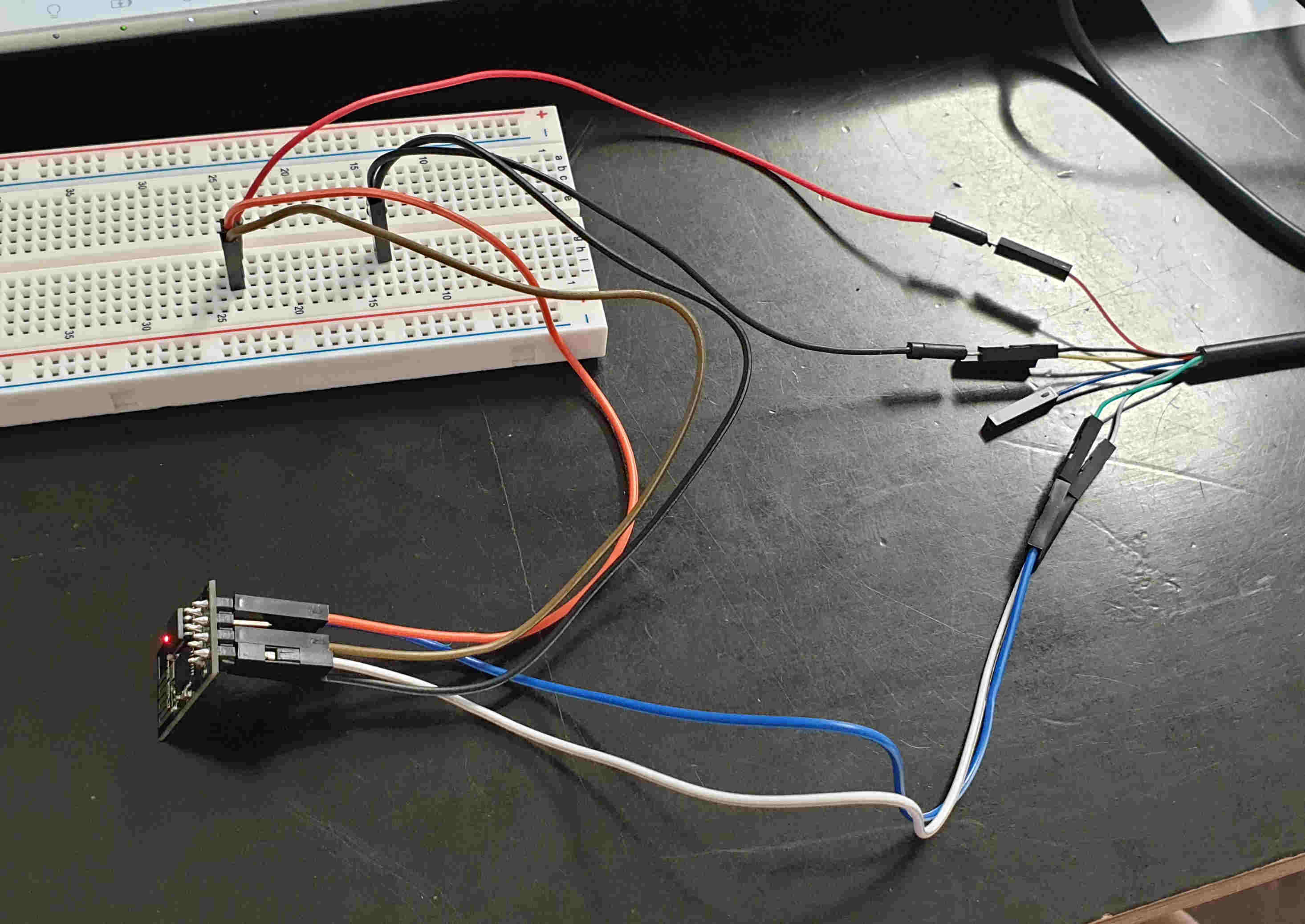
First two attempts were fail for me. For first attempt I used regular FTDI USB serial converter because he has option to connect ESP8266 on 3.3V, but after I connect all pins like it’s shown in picture, I got nothing, trying to connect it other ways and still nothing, on some attempt my board started to getting hot really fast so I went to check with multi meter am I using the correct VCC pin on FTDI. But I did. And here is how I connected it.
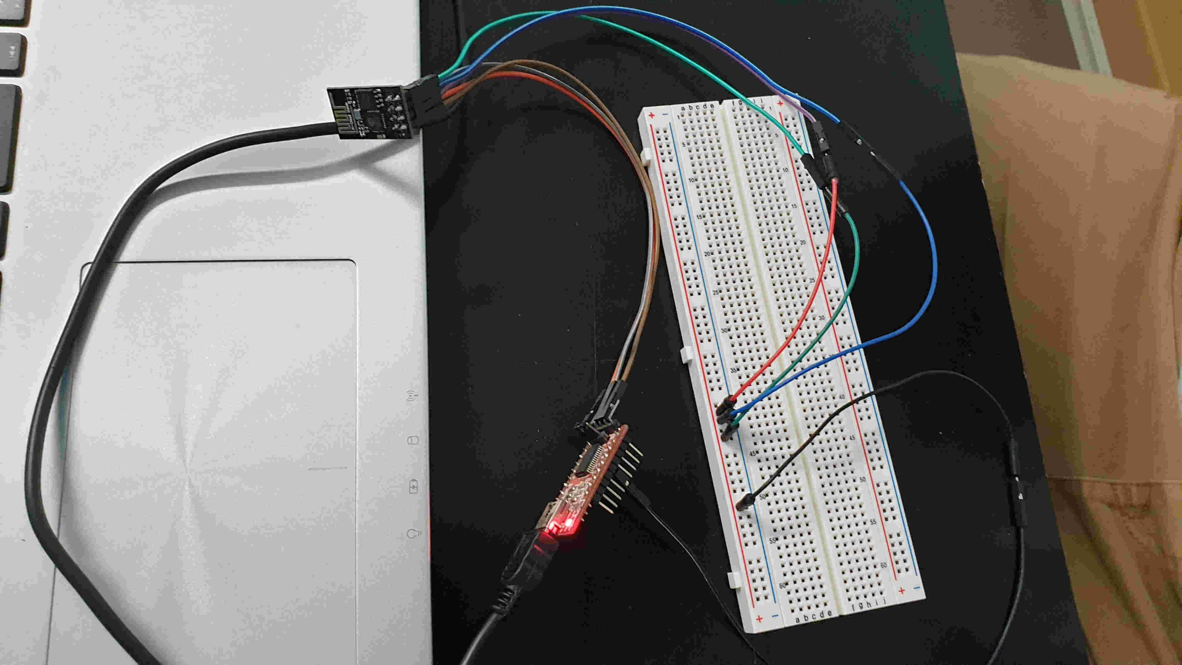
After that tried with FTDI cable that provides 3.3V and that attempt was successful.
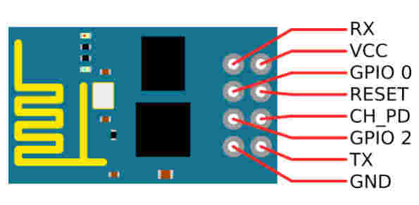
It’s hard to tell but the pins are connected in this order:
| FTDI | ESP8266-01 |
|---|---|
| RX | TX |
| TX | RX |
| VCC 3.3V | VCC |
| VCC 3.3V | CH_PD |
| GND | GND |
ESP8266, in it’s default configuration, boots up into the serial modem mode. In this mode you can communicate with it using a set of AT commands. Below you can see the commands that I run in “serial monitor” to connect it to wifi.
AT: test if AT system works correctly
AT+GMR: view version info (print firmware version)
AT+CWMODE=3: WIFI mode (station, AP, station+AP)-set AP’s info which will be connected by ESP8266
AT+CWLAP: list available Aps
AT+CWJAP “DEZENTRALE”,”NixFuerKinder”: connect to AP-commands ESP8266 to connect a SSID with supplied password
AT+CIFSR: get local IP address
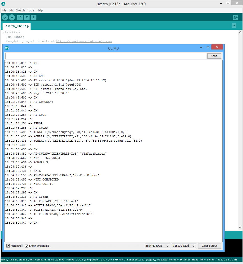
Those are command that I ran and can be seen on picture, for more AT commands visit ROOM-15 site where is great and detailed description for all commands.
To check does it really works I went to my wifi setting on laptop and mobile phone, it works.


And for the end of this part, a short video of working ESP8266-01 😊