OUTPUT DEVICES
12.WEEK
This assignment is most like one week earlier one, but this one is to test output devices. I'll use the board that I made last week in week 11. So I'll copy my documenttaion prom preawious week to show you my board design.
BOARD DESIGNE
First is to make a board so lets open Eagle first. Through this part I’ll be a little shorter and if you want to see detailed explanations on what you have to do and how in my week5 assignment.
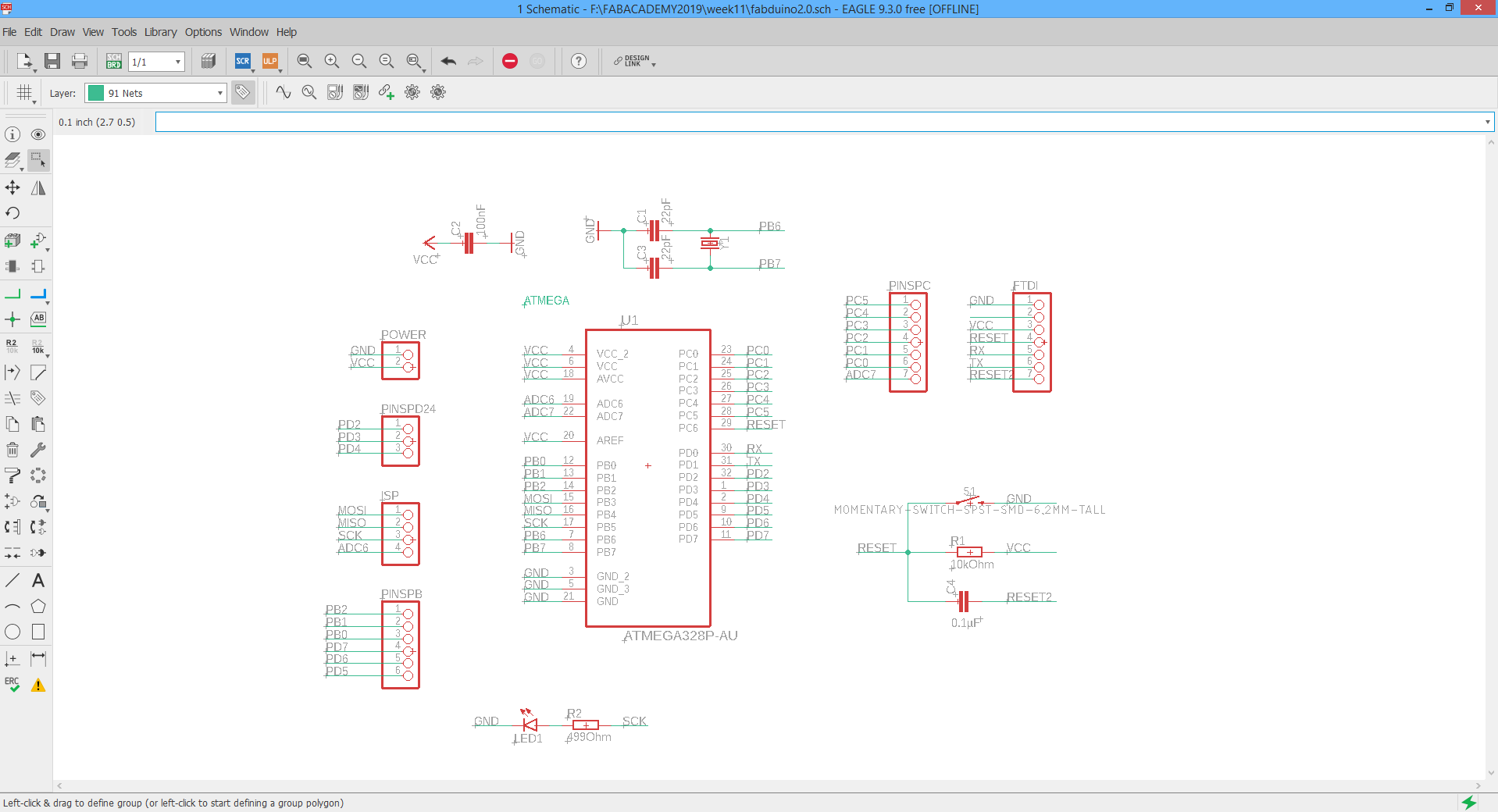
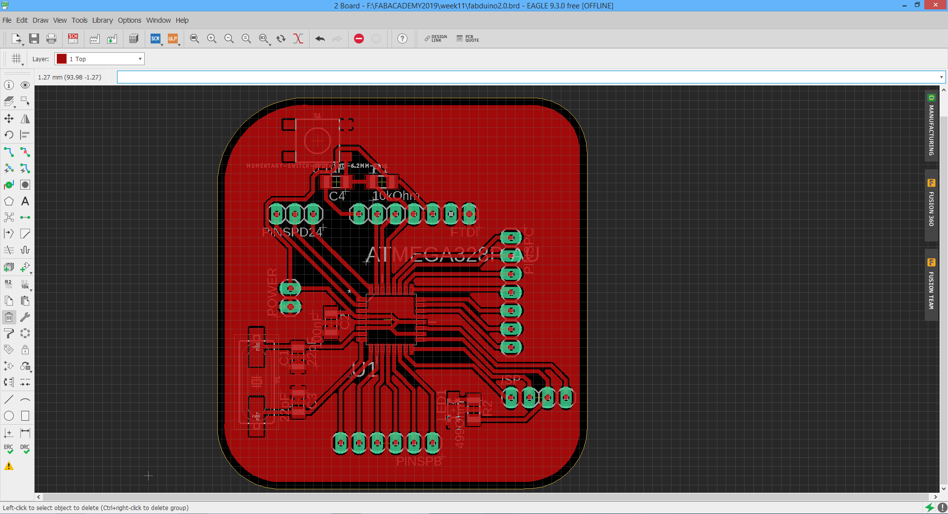
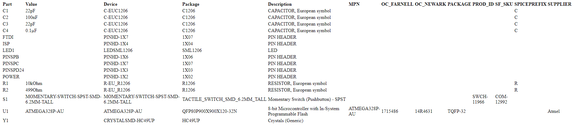
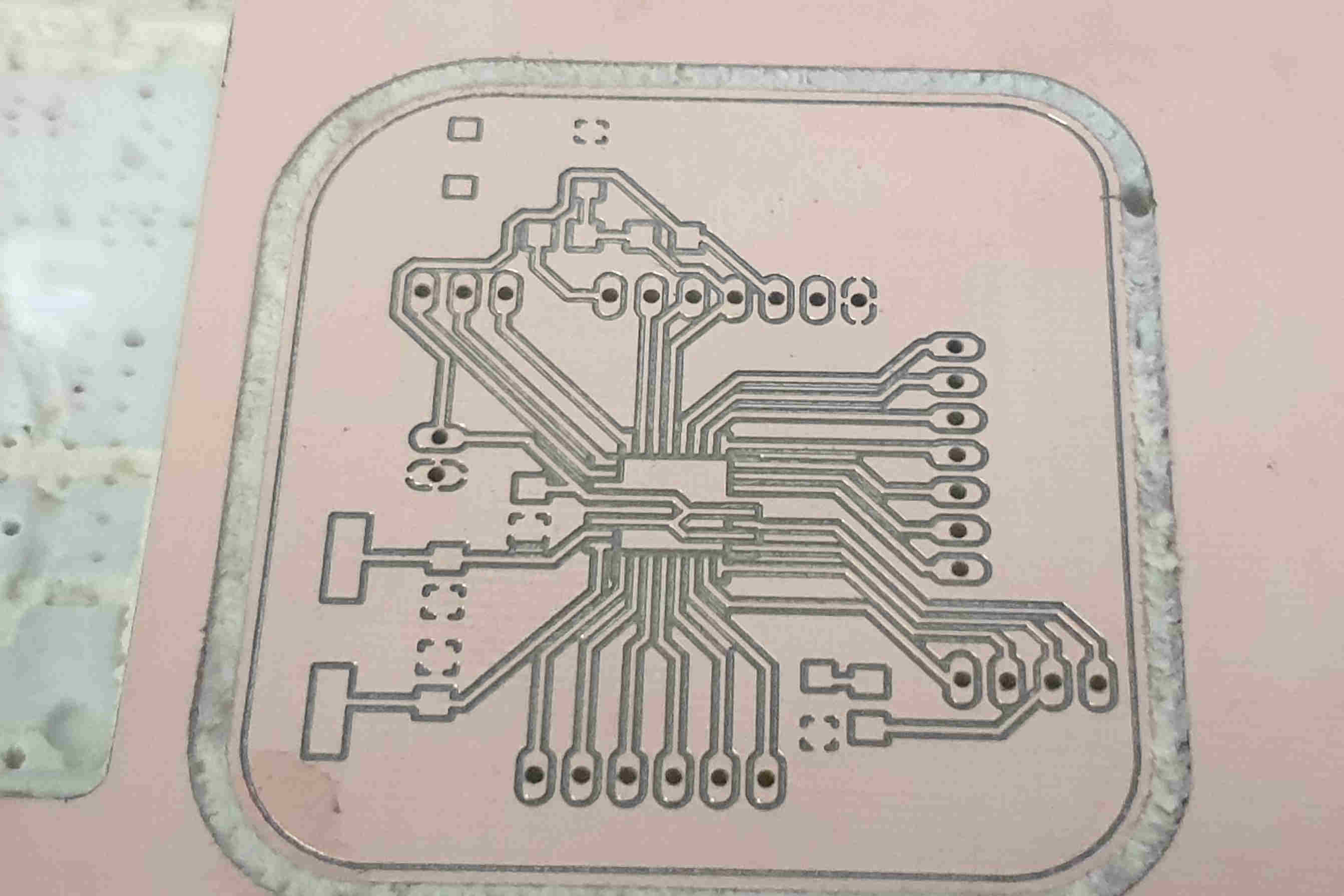
This is schamatic and board view of my "valentino" board, needed files I'll put on the end of the site so it can be downloaded and maybe can help someone. For me this is great board also for final project because the idea is to use only arduino compatibile sensors. Below I put BOM(bill of material so it's easier to redraw the board.
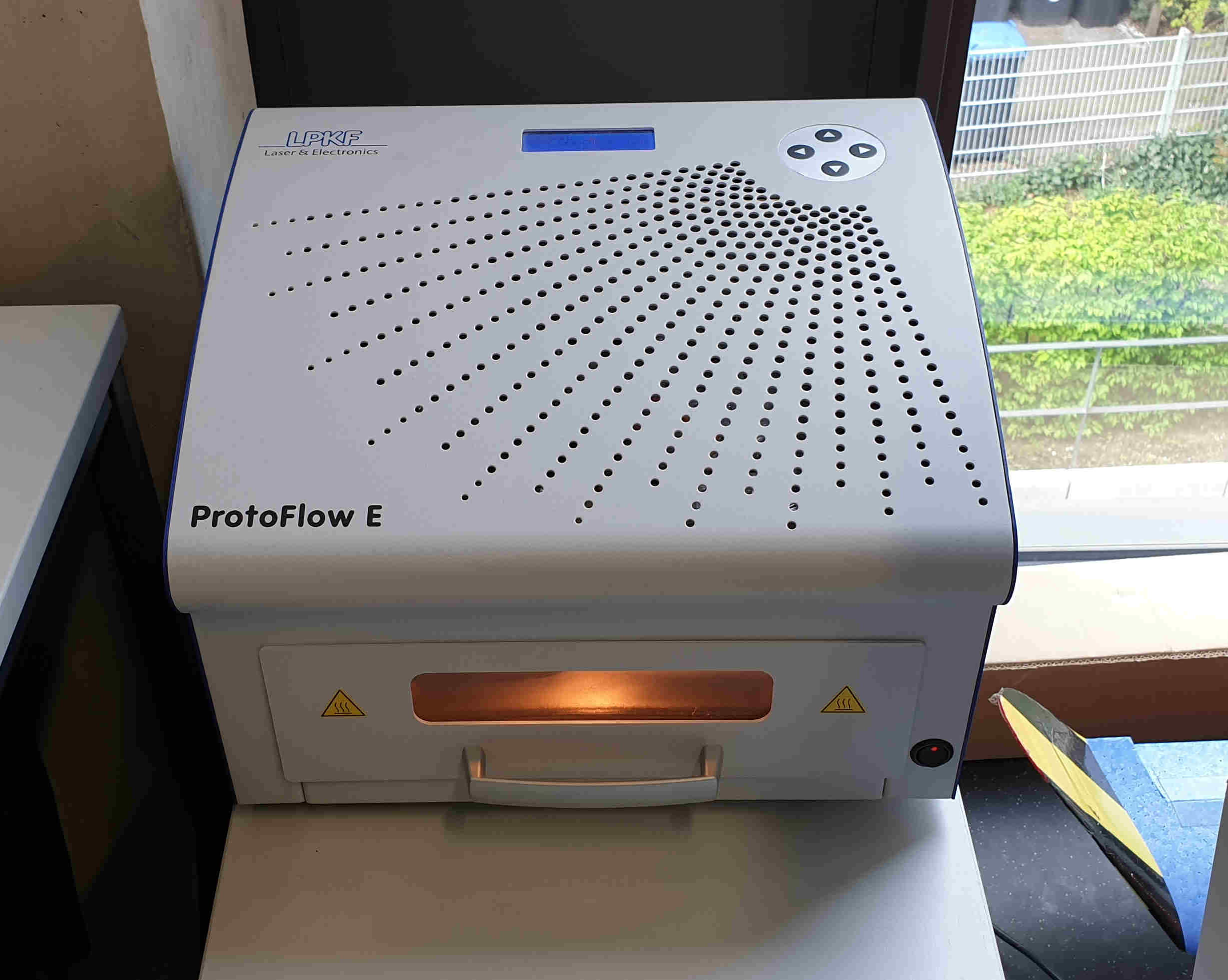
When I’m satisfied with the look of the board, need to save schematics and board design to USB and plug it in to lpkfs computer to mill the board. I’m gonna also skip a little bit that part of milling, cleaning, soldering and backing, that is also in my week 5 explained. But I’ll poste below some pictures and of course in the end of page .zip files for downloading.
Next steps for making the board after EAGLE are:
1. Pripare files and parameters for milling on LPKFs computer, set mill on it's zero position.
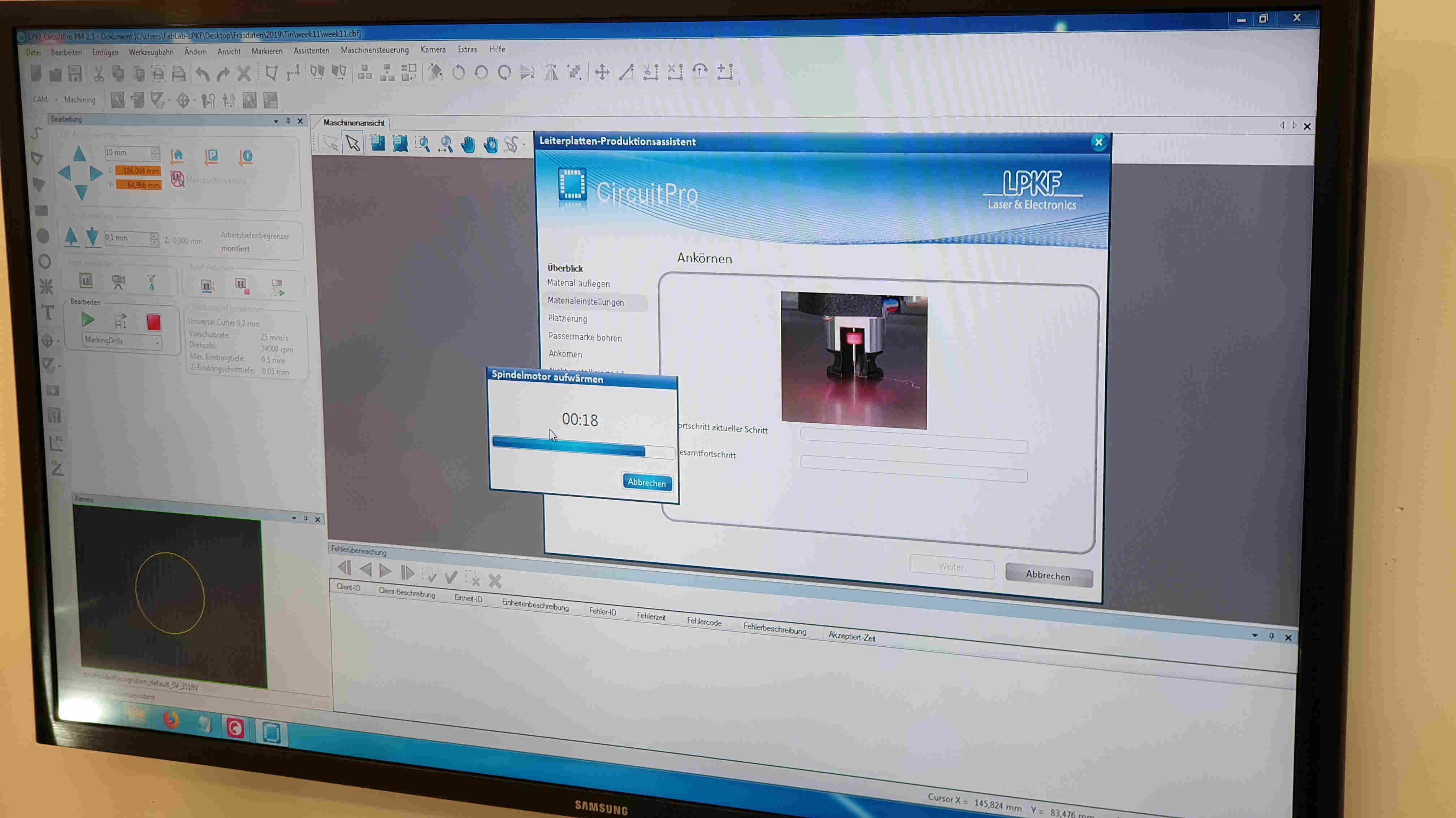
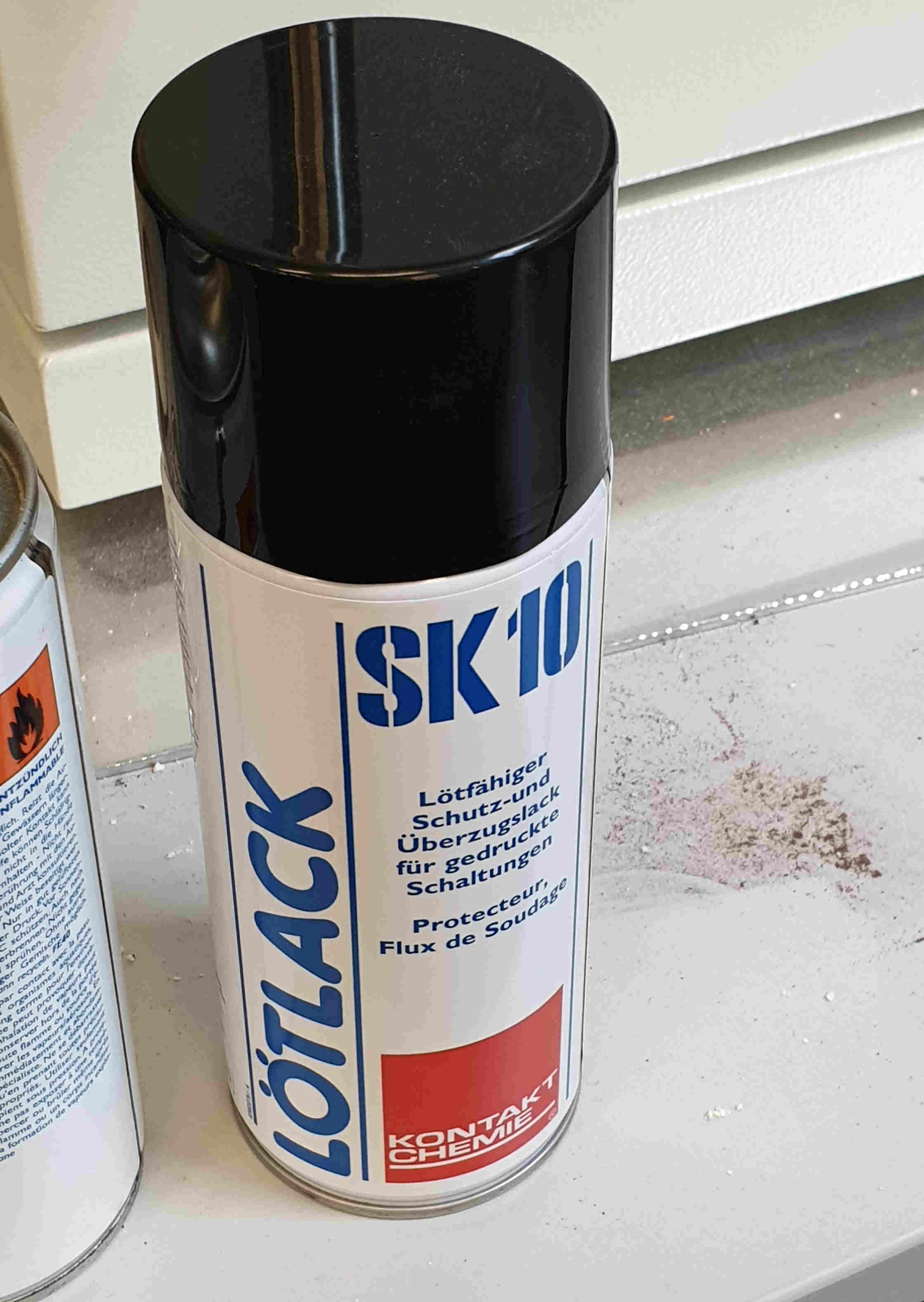
2. Now start job on mill and waite untill is done. Don't forget to always look on mill because of suden errors so you can react on time. Now when the board is done I have to clean it and spray it with SK10.
3. Using paste extruder to put solder paste on places where the components should come. This step depends on do you have pste extruder at your lab or not, if don't than is regular soldering needed.
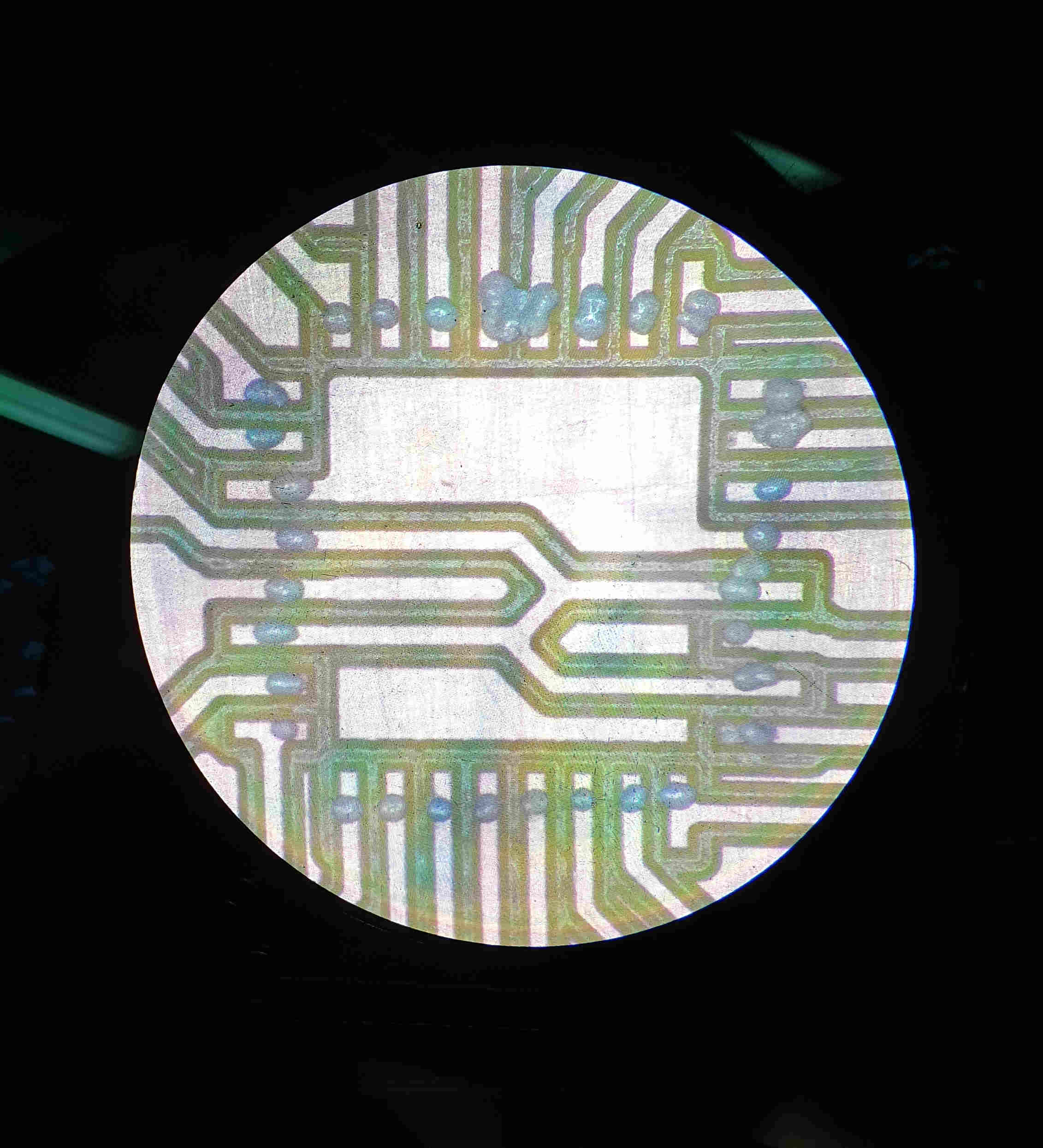
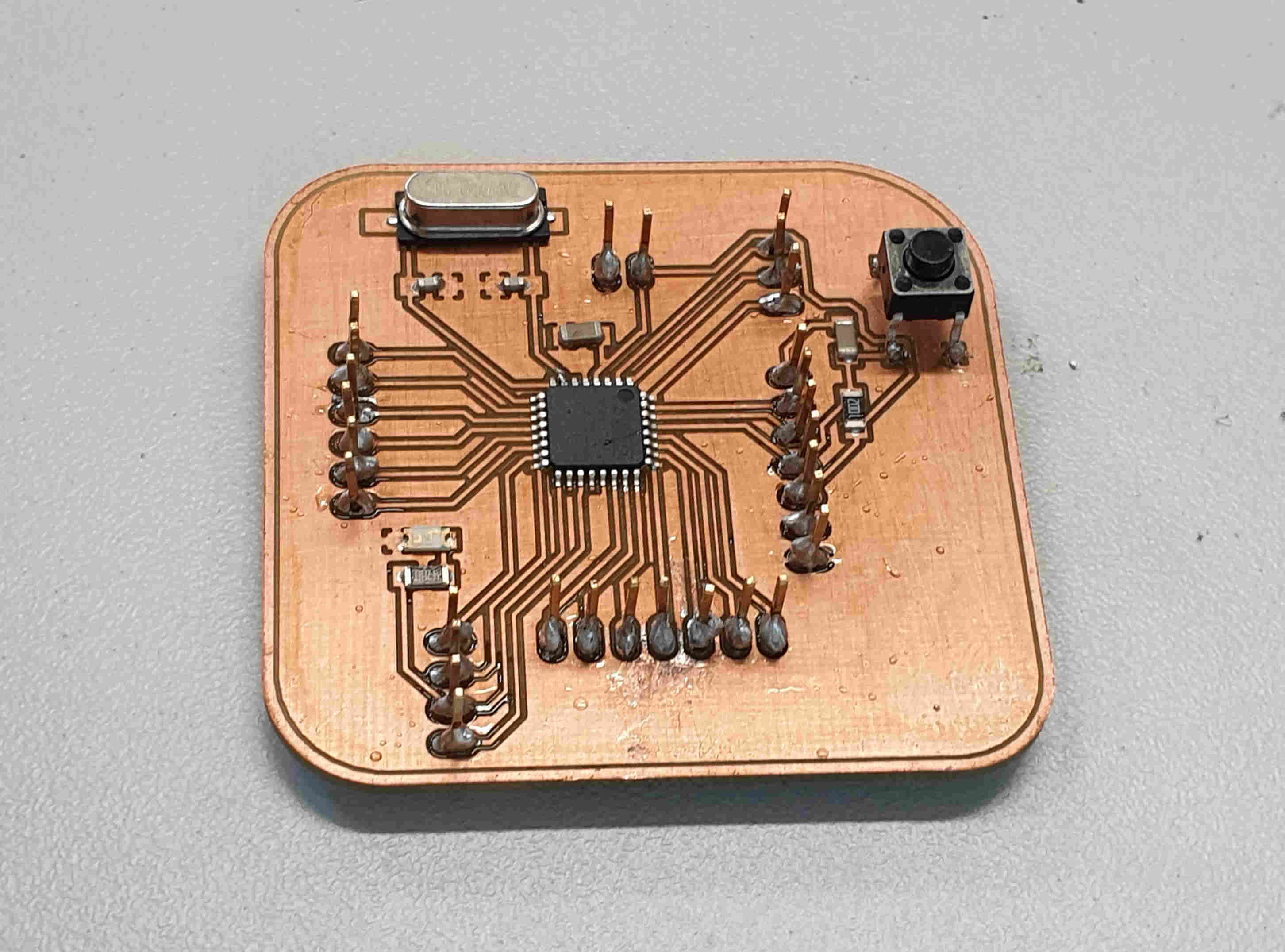
As you can see the secon piture is showing result of my shaking and unstady hands, but that is also unexperiance. I used tiny scalpel and microscope to remove all solder paste that was extra.
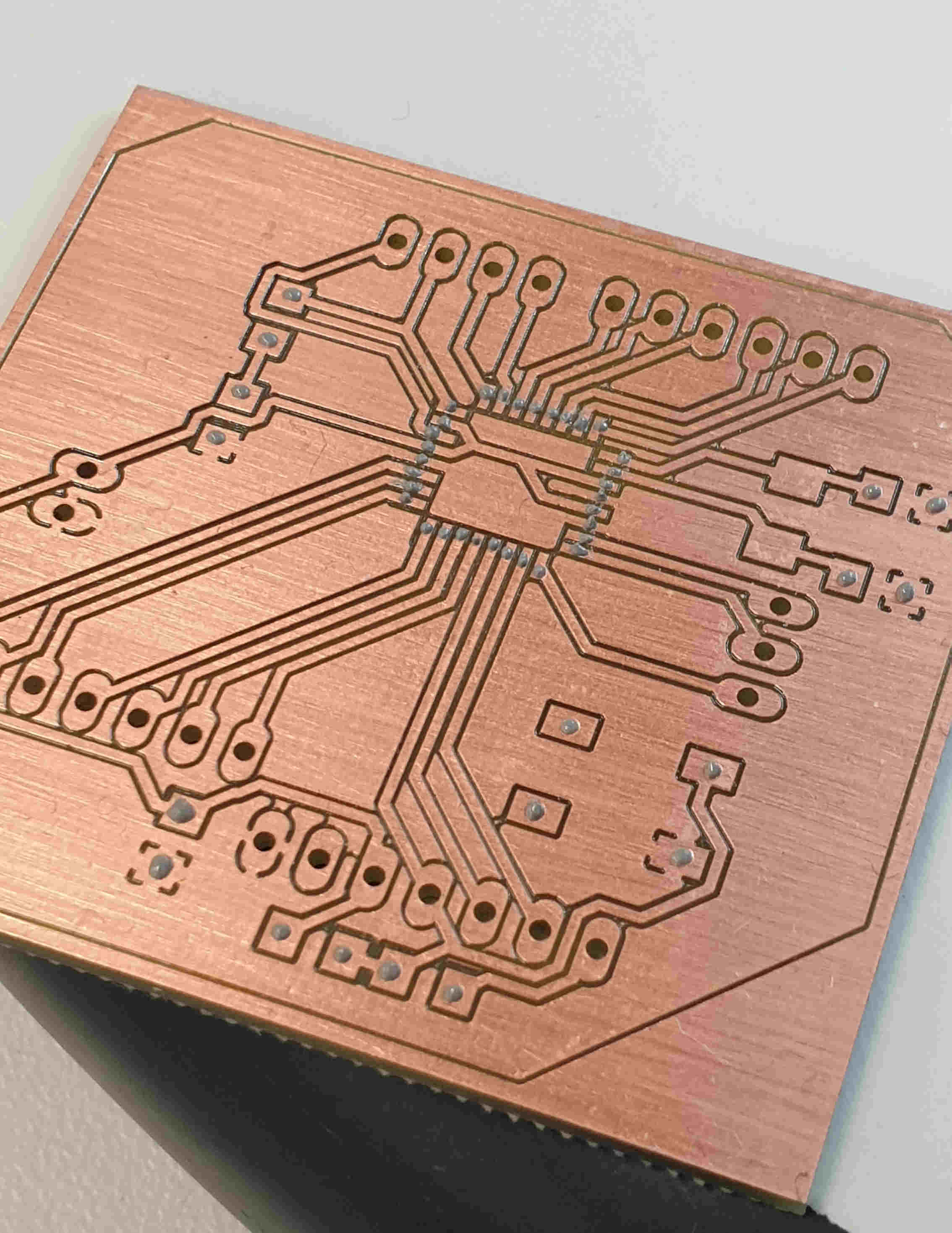
4. Then is turn to put all components on boar, this was also little bit tricki for me because of my shaking hand but somehow I did it. and after putting all components on, I need to put board in previously heatted oven. Oven makes sound when reflowing is done and the board is ready just needs to be cool down before use.
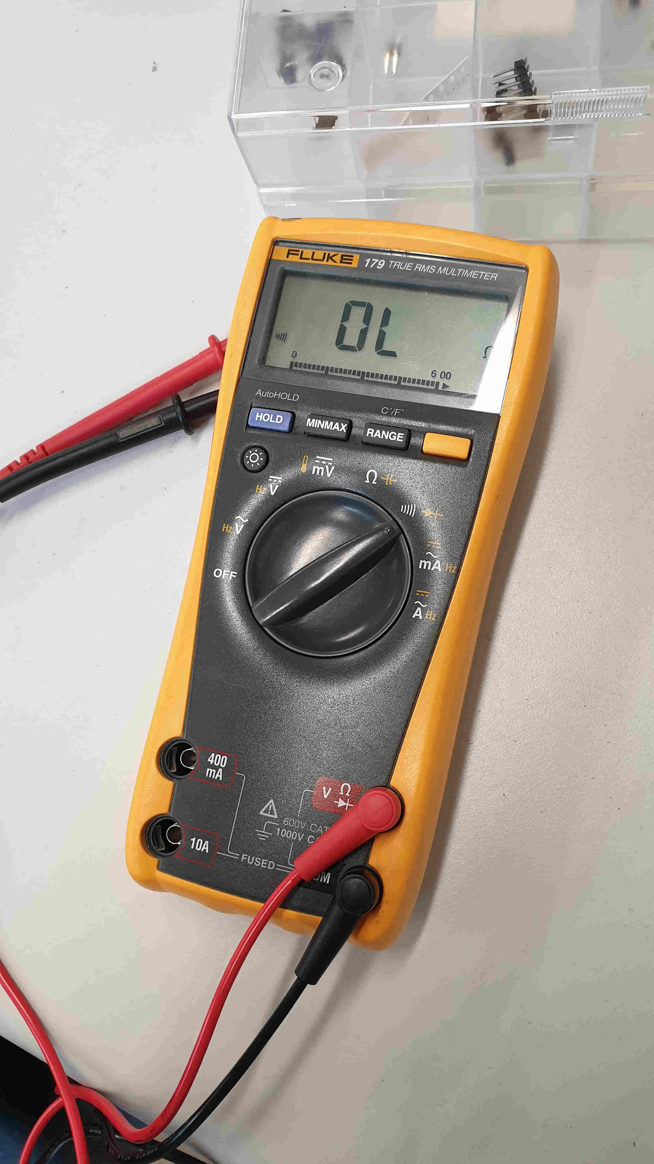
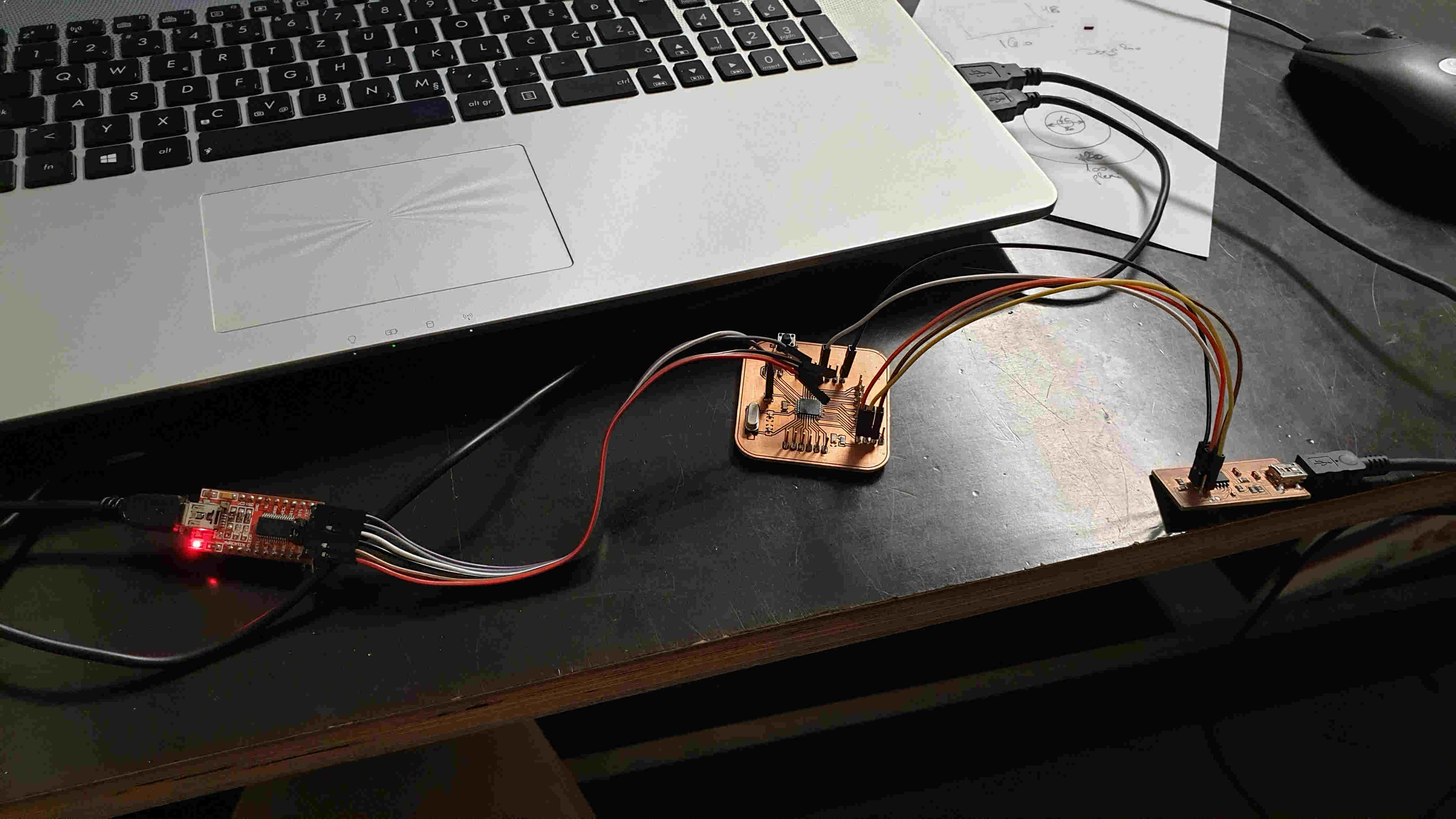
5. Last step before I can use it and test all the sensors. In previously weeks when I also needed to make PCBs I all the time forget relly important step, that's checking all connections with multimeter. This time I checked them, there were two bad connections, but after 5 minutes all was good. Now just to connect my valentino board to computer, with order of connecting ( computer>FABISP>valentino board>FTDI>computer), open Arduino IDE and run "burn bootloader", now the board is all set up for programming.
OUTPUT DEVICES
SERVO MOTOR
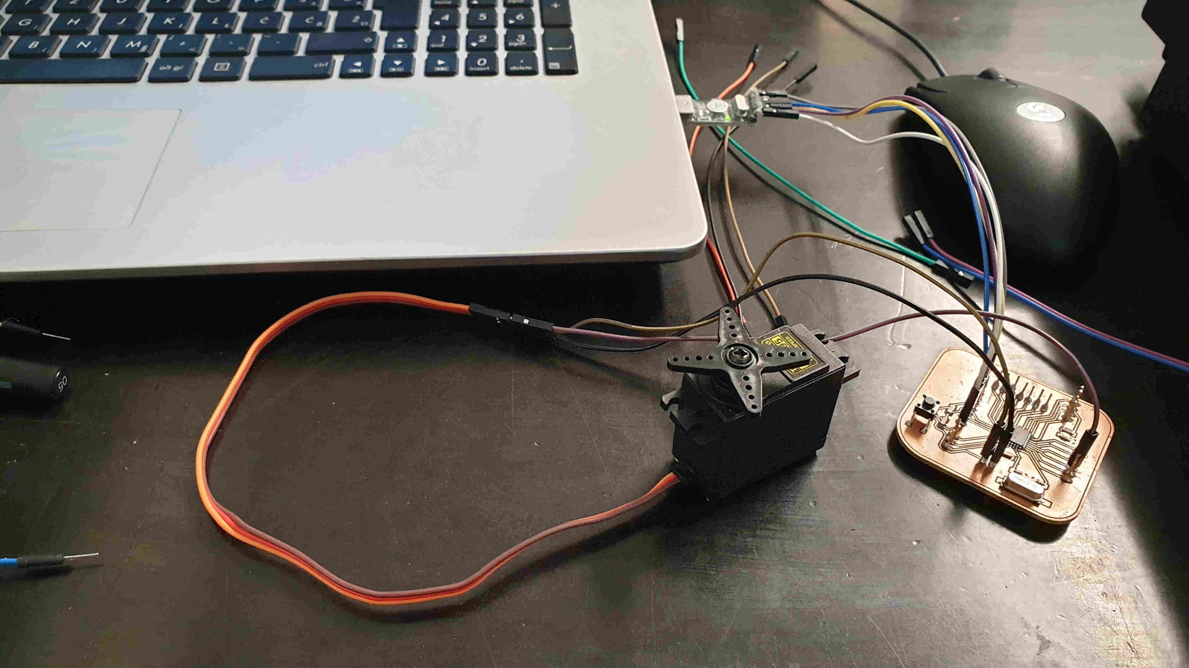
For output device I wanted to test servo motor. Now lets me first say something about servo motor and than I'll show results of testing with short video.
Servo motors are great devices that can turn to a specified position.Usually, they have a servo arm that can turn 180 degrees. A servo motor has everything built in: a motor, a feedback circuit, and most important, a motor driver. It just needs one power line, one ground, and one control pin
For first excercise I connect only sero mototr to my valentino board, put the code into Arduino IDE and upload it. Resolt of that you can see below.
#include <Servo.h>

Servo myservo;  // create servo object to control a servo
// twelve servo objects can be created on most boards

int pos = 0;    // variable to store the servo position

void setup() {
  myservo.attach(9);  // attaches the servo on pin 9 to the servo object
}

void loop() {
  for (pos = 0; pos <= 180; pos += 1) { // goes from 0 degrees to 180 degrees
    // in steps of 1 degree
    myservo.write(pos);              // tell servo to go to position in variable 'pos'
    delay(15);                       // waits 15ms for the servo to reach the position
  }
  for (pos = 180; pos >= 0; pos -= 1) { // goes from 180 degrees to 0 degrees
    myservo.write(pos);              // tell servo to go to position in variable 'pos'
    delay(15);                       // waits 15ms for the servo to reach the position
  }
}
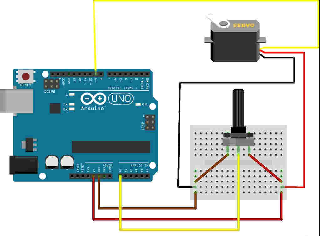
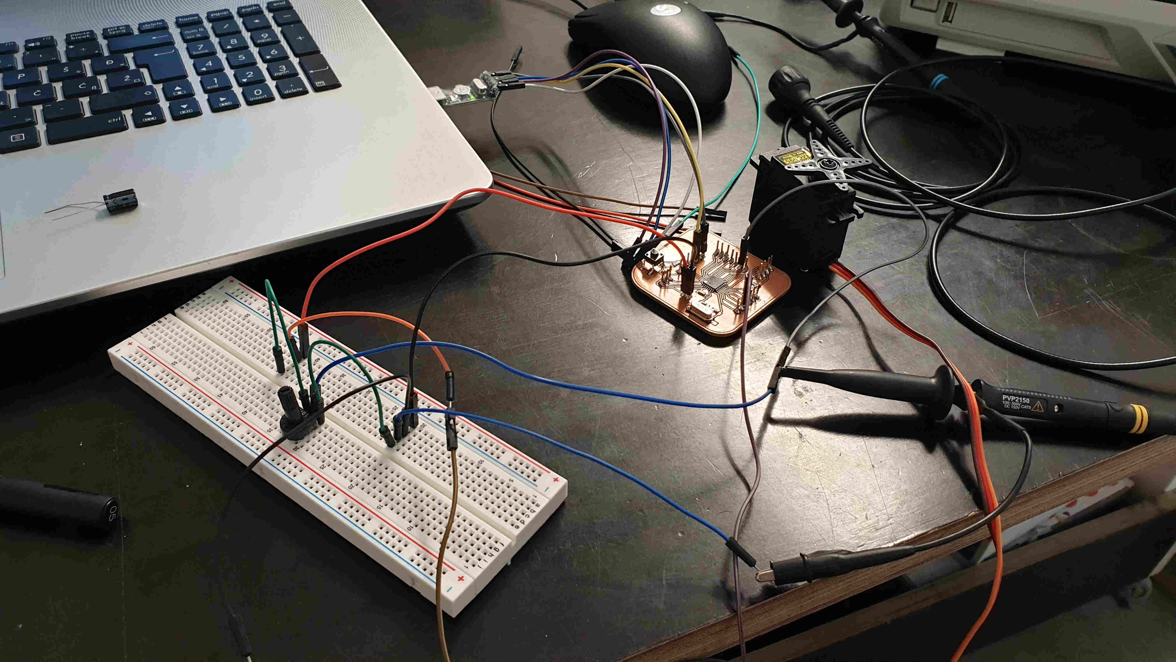
For second try I want to ad potentiometer to circuit and try to control the angle of servo motor with it. First is picture how to connect it and also the video of excercise.
#include <Servo.h>

Servo myservo;  // create servo object to control a servo

int potpin = 0;  // analog pin used to connect the potentiometer
int val;    // variable to read the value from the analog pin

void setup() {
  myservo.attach(9);  // attaches the servo on pin 9 to the servo object
}

void loop() {
  val = analogRead(potpin);            // reads the value of the potentiometer (value between 0 and 1023)
  val = map(val, 0, 1023, 0, 180);     // scale it to use it with the servo (value between 0 and 180)
  myservo.write(val);                  // sets the servo position according to the scaled value
  delay(15);                           // waits for the servo to get there
}
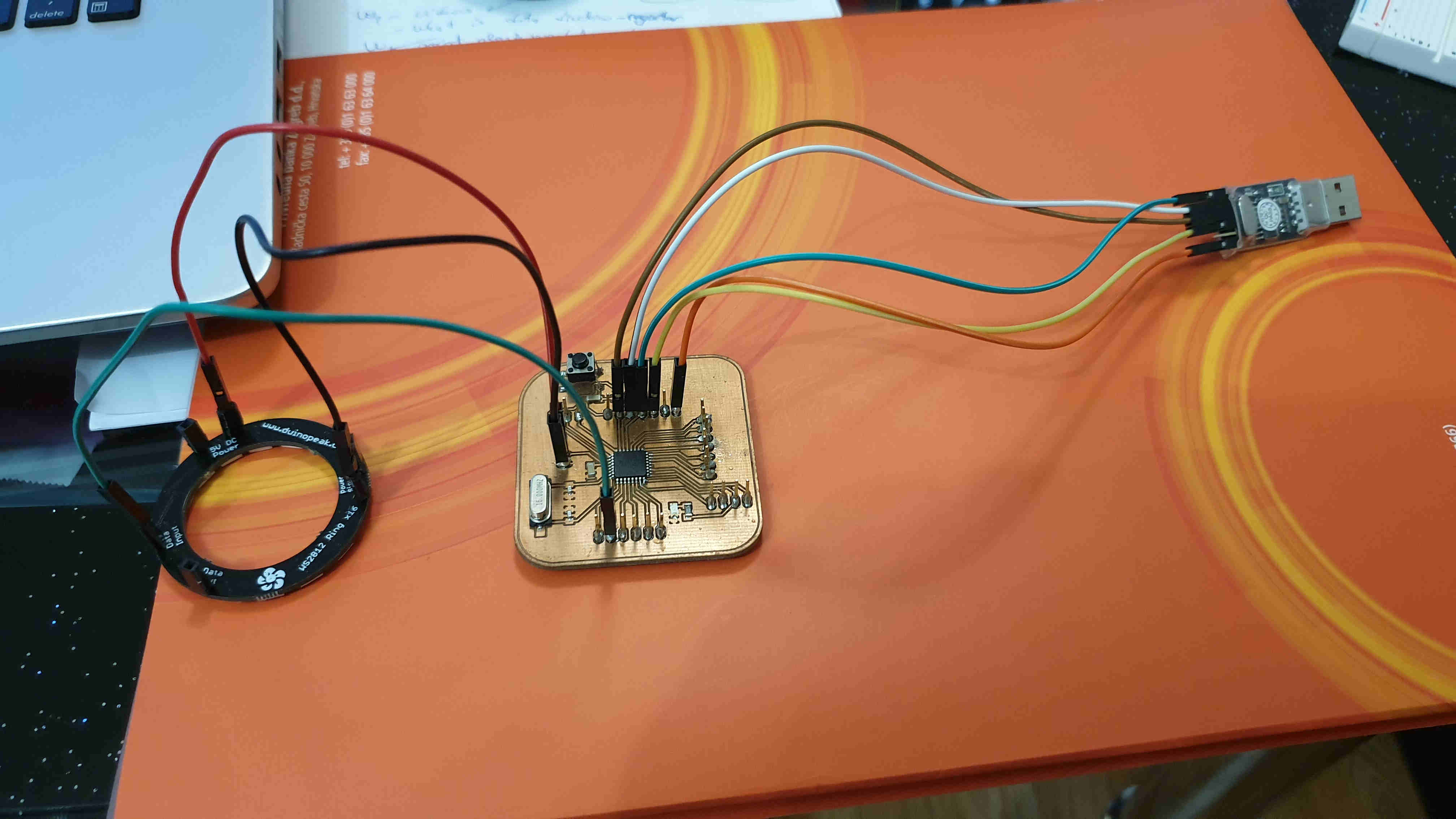
ADAFRUIT NEOPIXEL RING
For next test I wanted to test main part of my final project and that is light so I took Adafruits Neopixel x16 ring, connet it to my board and run one arduino code for example. The results were amazing. Firs I need to instal Adafruit nepixel library so the cod could work. Only thing in this code and others when you are using neopixel is to don't forget to change LED pin that is connected to board and neopixels INPUT, also to change number of LEDs that you are using. After setting all up I ran the code bellow and it was working.
#include <Adafruit_NeoPixel.h>

// constants won't change. They're used here to
// set pin numbers:
const int ledPin = 6;     // the number of the neopixel strip
const int numLeds = 16;

//Adafruit_NeoPixel pixels = Adafruit_NeoPixel(8, ledPin);
Adafruit_NeoPixel strip = Adafruit_NeoPixel(numLeds, ledPin, NEO_GRB + NEO_KHZ800);


void setup() {
  strip.begin();
  strip.setBrightness(255); // 1/3 brightness

}

void loop() {


    rainbow(30);

  delay(10);


}


void rainbow(uint8_t wait) {
  uint16_t i, j;

  for(j=0; j<256; j++) {
    for(i=0; i<strip.numPixels(); i++) {
      strip.setPixelColor(i, Wheel((i*1+j) & 255));
    }
    strip.show();
    delay(wait);
  }
}


// Input a value 0 to 255 to get a color value.
// The colours are a transition r - g - b - back to r.
uint32_t Wheel(byte WheelPos) {
  if(WheelPos < 85) {
    return strip.Color(WheelPos * 3, 255 - WheelPos * 3, 0);
  }
  else if(WheelPos < 170) {
    WheelPos -= 85;
    return strip.Color(255 - WheelPos * 3, 0, WheelPos * 3);
  }
  else {
    WheelPos -= 170;
    return strip.Color(0, WheelPos * 3, 255 - WheelPos * 3);
  }
}
And there is also video to see the live results.