4. Computer controlled cutting
Group Assignment:
Machine Testing
Our idea was to use one of the Trotec machines, either the 100 or the 400, but they were being used all morning by other students, so after waiting for a while we finally decided to do it on the old and huge MultiCam 2000. Our instructor Mikel Llobera helped us through the process. This would have been really impossible without him, given the complicated interface of the machine, not to mention that some parts of it are not working properly.
The group set out to perform laser cutting and engraving on a 4mm undulated cardboard sheet. From the BCN FabLab Wiki, default parameters were taken.
- Carboard 4mm Rippled:
- CUT — Speed: 100; Power: 150
- ENGRAVE — Speed: 100; Power: 65
File Preparation
Vectors
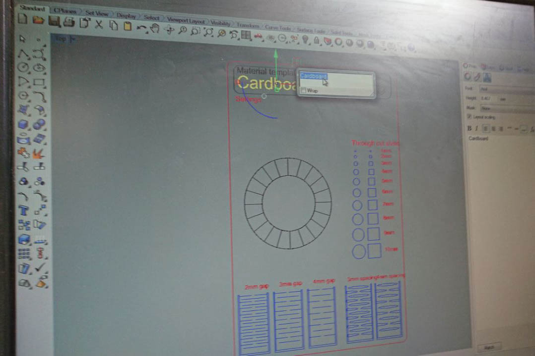
Fig 1. A design to perform laser-cutting on different material, ideal to test machine's parameters.
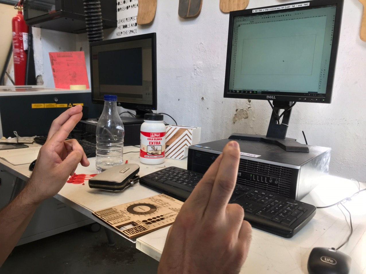
Fig 2. After setting some instructions through Rhino, by assigning each component its proper colour and layer, the file needs to be imported in the machine driver software. Hope does help.
Machine Settings
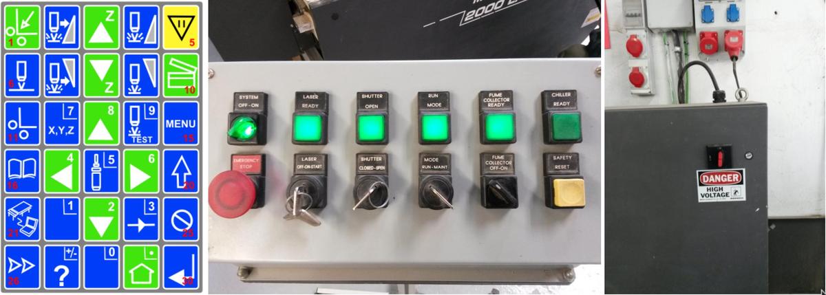 Berfore anything else: Turn on Air Extraction;
A mandatory step to avoid any trouble coming from the laser and to apply a suctioning force to the piece of material; this will allow the surface to stick to the laser cutting plane.
Cutting!
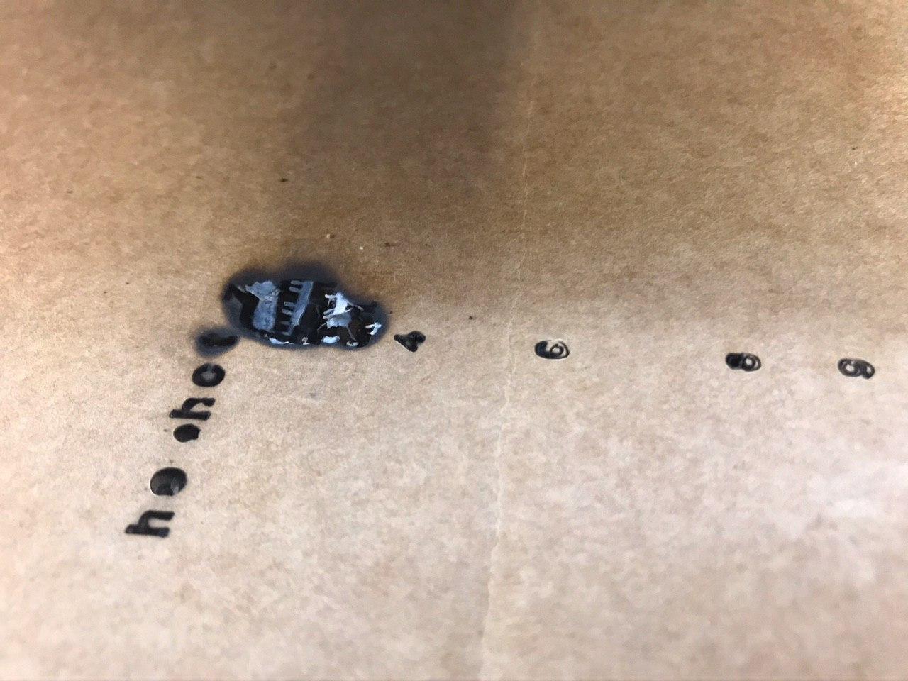
Fig 3. Oops.
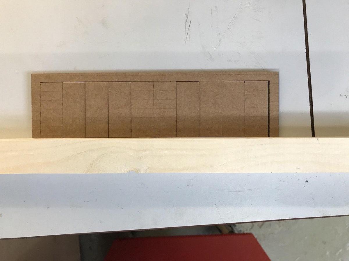
After a few trials the correct combination of speed and power for the cardboard used was found. The cutting speed was kept at 100, still delivering a pretty fast job; due to material properties, the power was lowered to by 50, getting to 100.
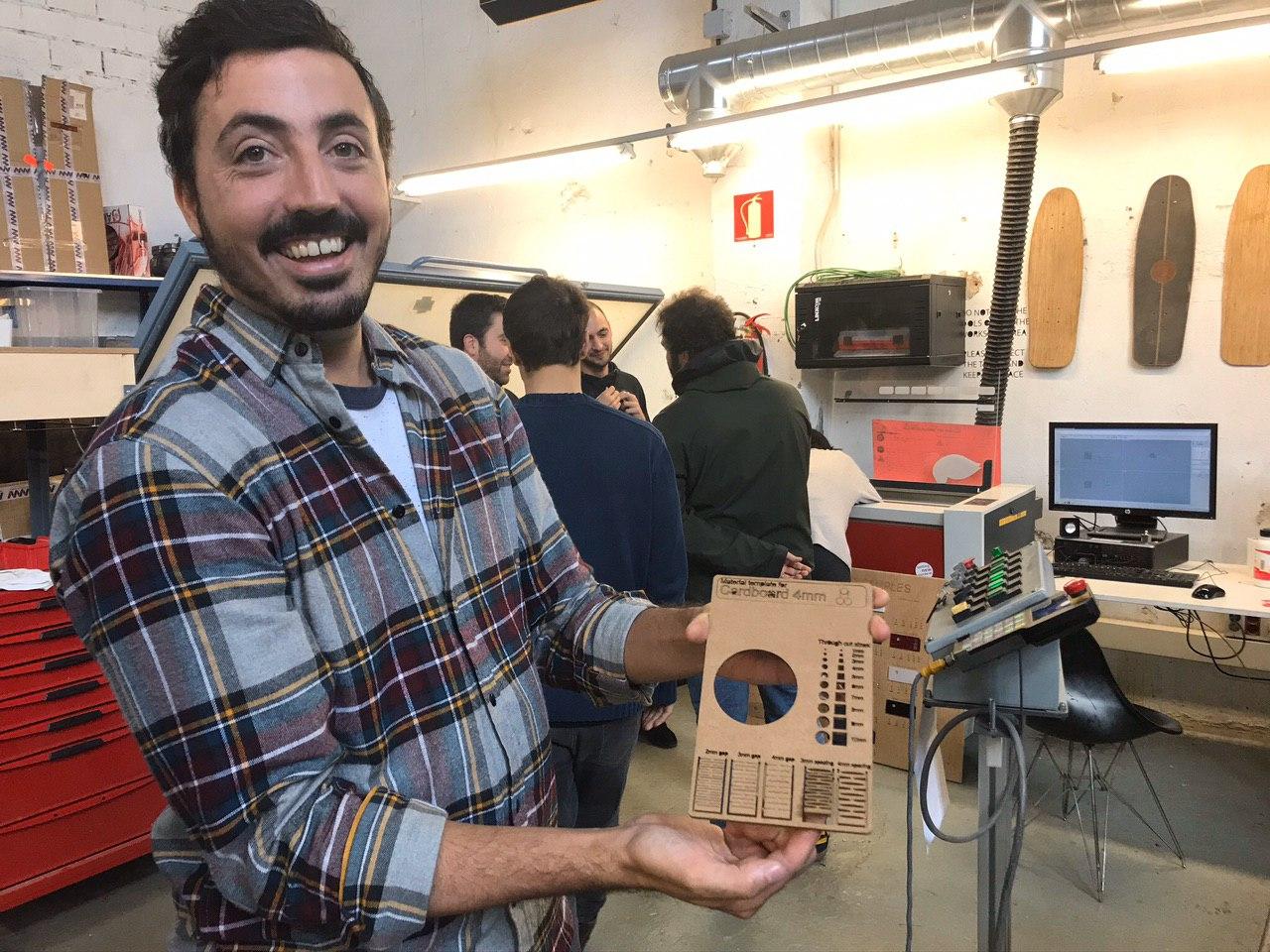
Fig 4. Bruno is relieved, the lab didn't catch on fire. As a total plus, the cut hinges are working.
Kerfing
Directly from Antoine's page
As part of my group, Fab Academy Student Antoine Jaunard, took care of measuring this machine kerfing.
He designed a strip with multiple cuts along the main dimension.
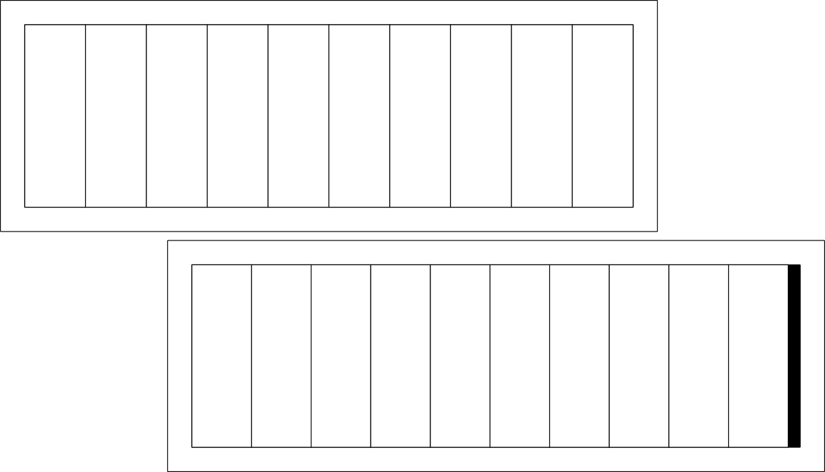 The idea is to cut a material several times, bring the cut pieces together and compare the final total width with the initial width. The difference should be the space left by the cut, from which we can get the value of the kerf.
Material | Intended | Actual | Difference | Kerf (difference/10) Offset | (kerf/2) --- |---|---|---|---|---| Cardboard 4mm | 200mm | 194mm | 6mm | 0.3mm | 0.15mm
 This technique could be applied to different materials with different settings (speed/power) by using this single template.
Laser Cutting a Parametric Construction Kit
Design
Grasshopper led me from week03 to week04 (or is it week02 to week03? I still don't get it, as the website template doesn't really match with the common naming.)
After familiarizing with the software basic functions, I used it to design the most simple construction module: a triangular surface with negative connections.

Fig 5. With the help of some parameters, the width and depth of the negative connections can be adjusted to the material thickness and piece dimensions.
Once my design was finalized for the laser cutter, I followed the same procedure from the group assignment, this time on a different machine.
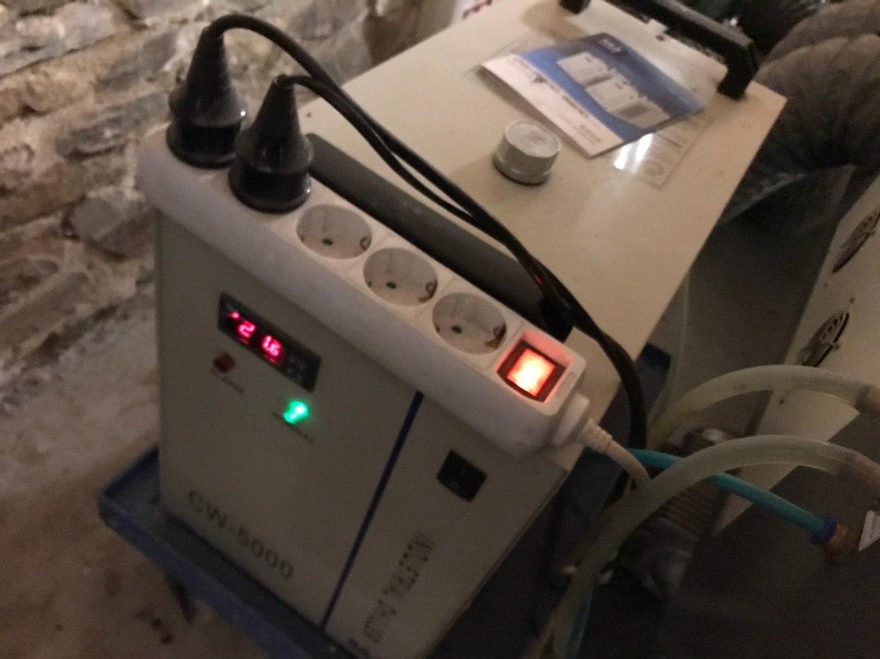
Fig 6. Being a closed one, this machine also has a water cooling component; its functioning is mandatory before we can turn the laser machine on.
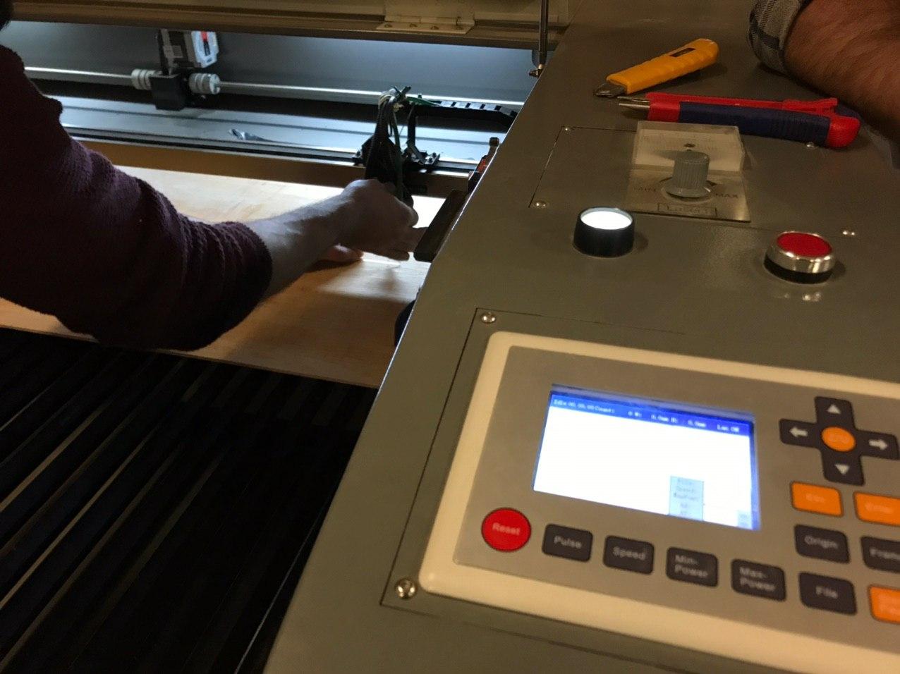
Fig 7. Positioning the laser head at the correct height for the lens focus: 9mm.
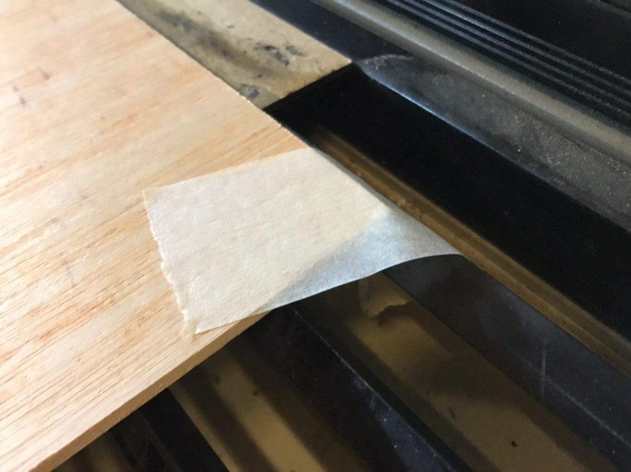
Fig 8. To help the sheet of material adhere to the cutting surface, place it against its curvature and tape it to the side of the machine, when necessary.
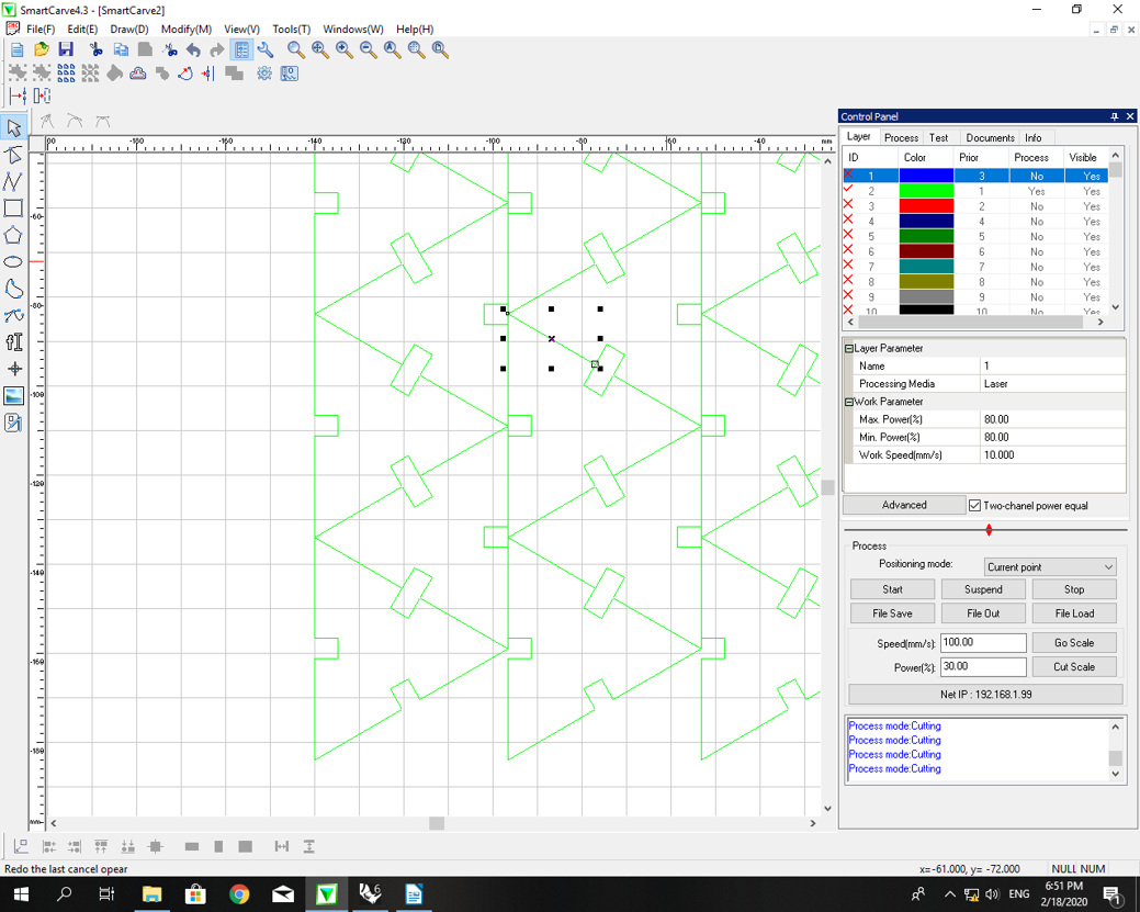
Fig 9. After arranging an array of pieces in Rhino, the file was exported with separated layers in an illustrator file format and fed to the machine SmatCarve software, where the cutting parameters were set following a guide for plywood.
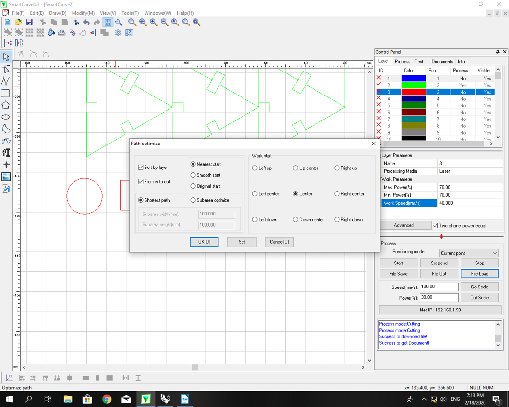
Fig 10. A good step is to optimize the cutting path, to reduce the job's time. Not too much though as if the laser spends too long on a single portion of the cutting area, there are more chances of overheating the material and burning it.
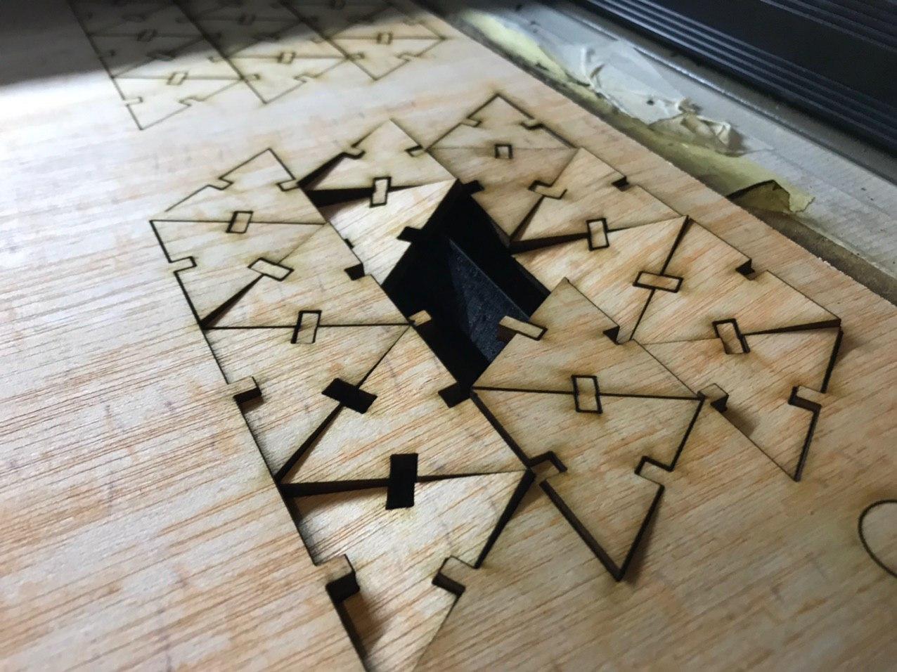
Fig 11. Oops #2.The pieces arrangement did not work, as the machine's grid holding the sheet of material has a quite large mesh, and the single pieces would start falling during the cutting.
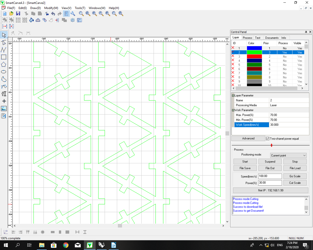
Fig 12. Fixed! A small adjustment in the disposition to leave a frame around each piece.
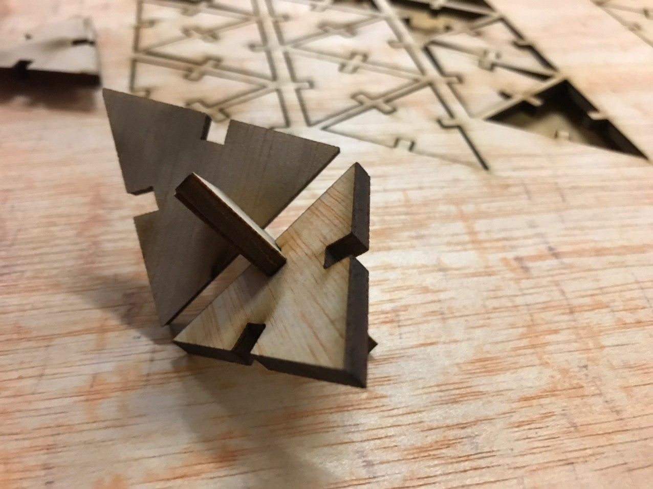
Fig 13. It works! But still, no chamfer...
fab academy week04 - computer controlled cutting from Marco Cataffo on Vimeo.