4. Electronics production
Characterize the design rules for your PCB production process.
the material
the milling machine
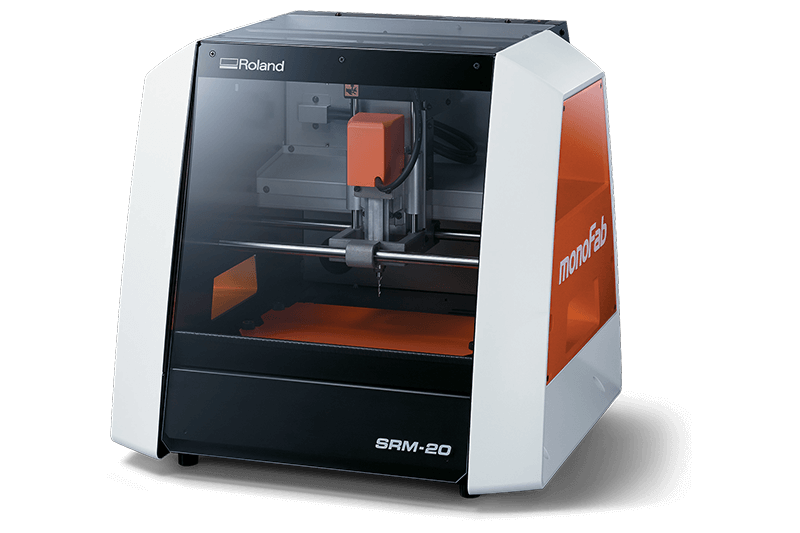
we use the Roland SRM 20. the machine can mill Modeling Wax, Chemical Wood, Foam, Acrylic, Poly acetate, ABS, PC board (PCB)
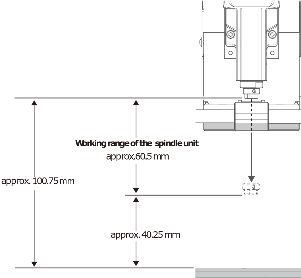
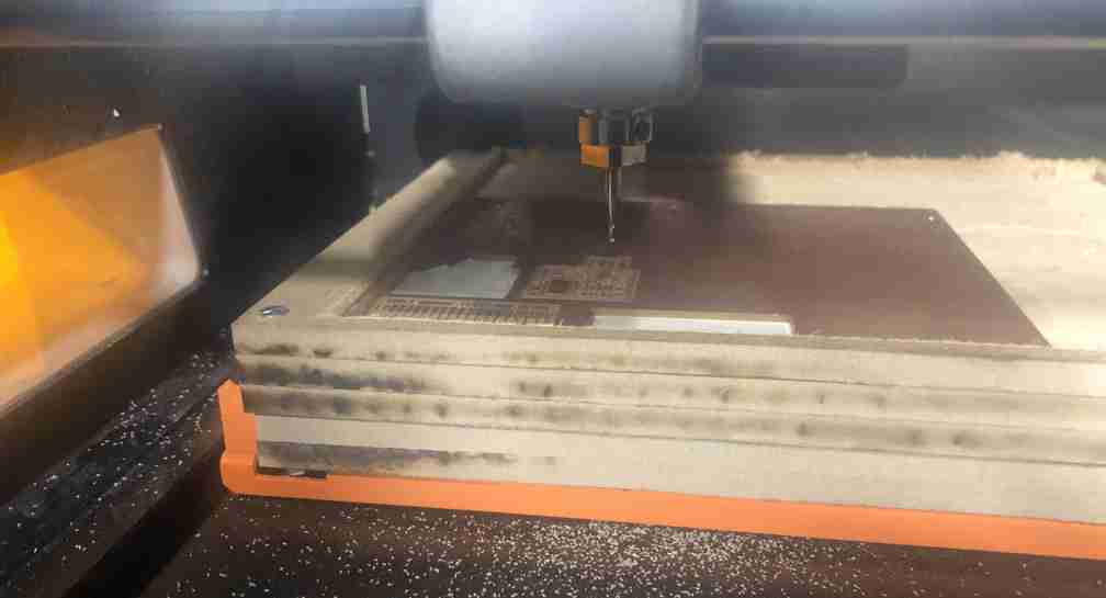
0,4 or 1 mm endmill is small and, even with the lowest position, the spindle cannot reach the PCB blank on the table. You need some extra spacers. We do that with several MDF joined layers, which become the sacrificial board when the milling is too deep.
You have to be carefull when you install the endmill because it’s very fragile. Don’t let it fall
The machine it self has a “hardware” zero position (x,y and z) but your job a one as well. You will have to set the 0 level of the Z axis of your job, depending on the attachment of the endmill . The x,y depends on where the PCB blank is installed and also depends on your design
this machine accept 2 Languages : RML-1 (roland standard) .rml , NC code (general language) .nccode
the different steps.
Preparing the milling
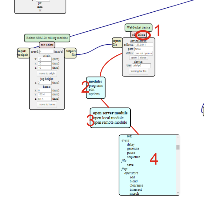
Mods
first, you have to choose the in-circuit programmer. For me, it’s CMSIS-DAP.10.D11C.
you need 2 .png files :
- for the trace (to remove the thin layer of copper)
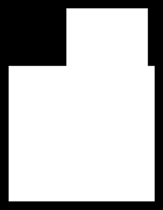
- for the cut of the exterior (to detach the work from the entire board)
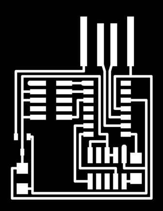
because it’s .png files, with a large zoom we see the limit of the fineness of the drawing up to the pixel limit.
2 files because you need to mill 2 times with different endmill and different deep and speed
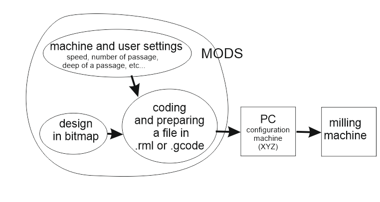
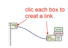
to prepare the files, we use mods. Mods does not work with Edge. So we use Chrome.
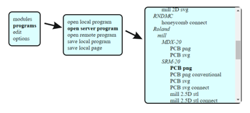
those first choices will open a more detailed screen
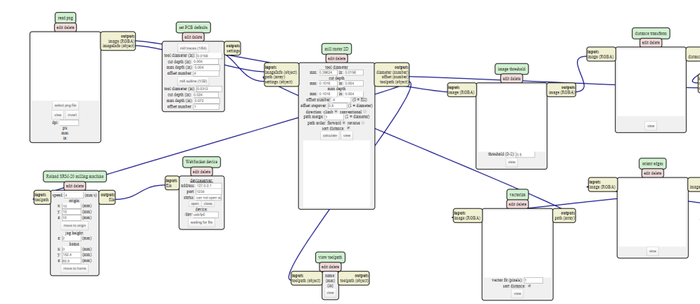
the different criteria to monitor
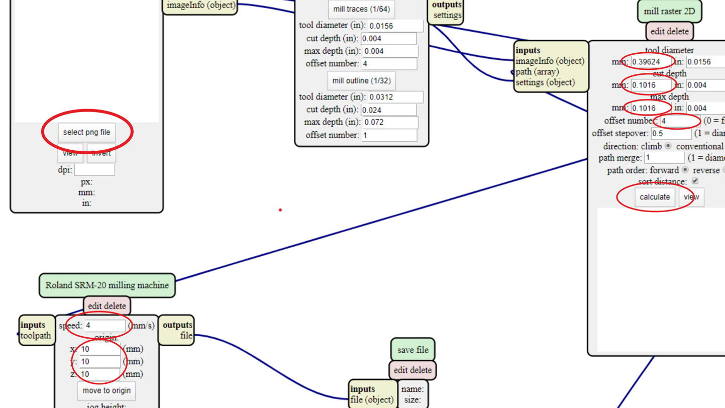
- A : size of the endmill
- B : total of the deep to cut
- C : deep to cut on each pass (never more than half size of the endmill)
- D : number of offset to enlarge the cut
- E : movement speed
- F : other elements. keep at 0
configuration for the trace file
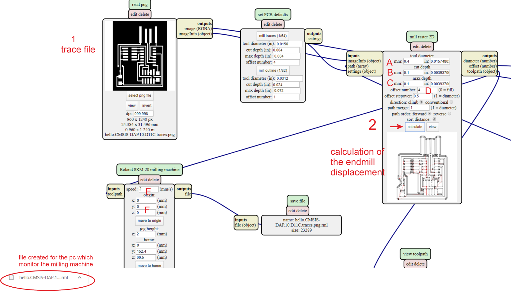
detail of the movement of the endmill

configuration for the interior file (cut of the piece from the board)
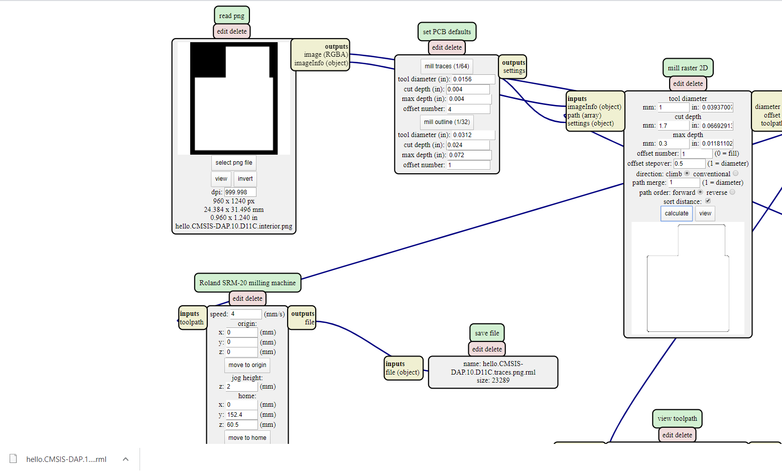
If no file is generated, there is a configuration problem Example : inverting max depth and cut depth
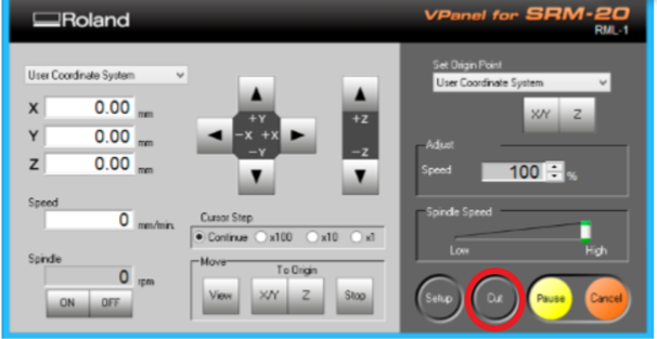
VPanel for SRM-20
on the computer linked to the milling machine, i use VPanel for SRM-20 for 2 main actions :
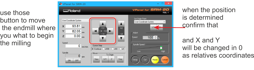
- adjusting the position of the endmill (x, y, z)
- outputing the files to the milling machine
The PCB Blanck
I used double side tape to fix the PCB blank to the sacrificial board. The tape must be laid precisely without bubbles. The PCB blank must be glued as strongly as possible and as horizontal as possible.
~~i use Bare copper card, Simple face, 150 x 100 x 1.6mm, xxxxxμm, FR1,reference xxxxxxx ; reference constructor : xxxxxx , specification : https://xxxxxxxx~~
X Y of the milling machine.
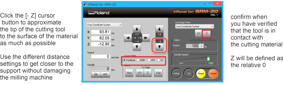
Z of the milling machine.
.
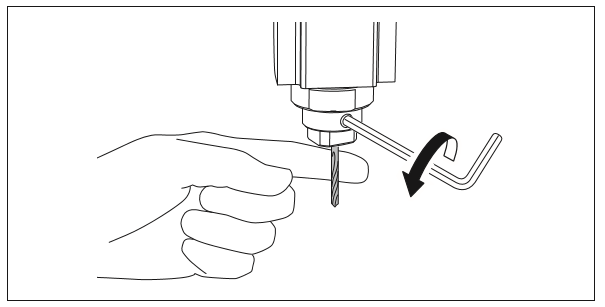
you can loose the set screw, and adjust the cutting tool so that its tip contacts the surface of the material, but you have to support lightly by hand not to drop a the endmill
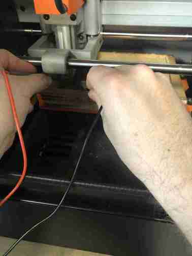
how to have a correct user 0 on Z axis ?
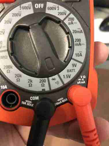
you can check the contact by checking the electric continuity
the setting of the control device
you touch the endmill and the PCB, if it beeps, it touch so you have a correct 0
Beginning of the mill
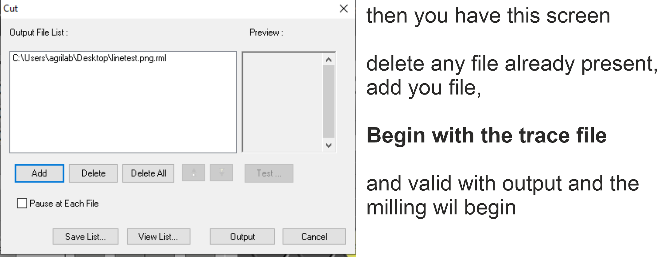
you begin by the trace file
and after the interior file to cut from PCB blank
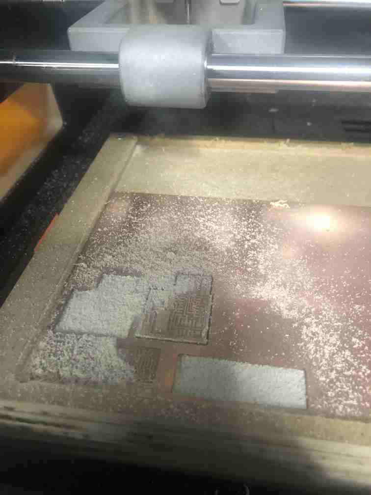
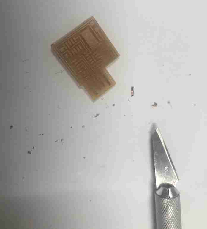
after melling, the piece is like that but not finished
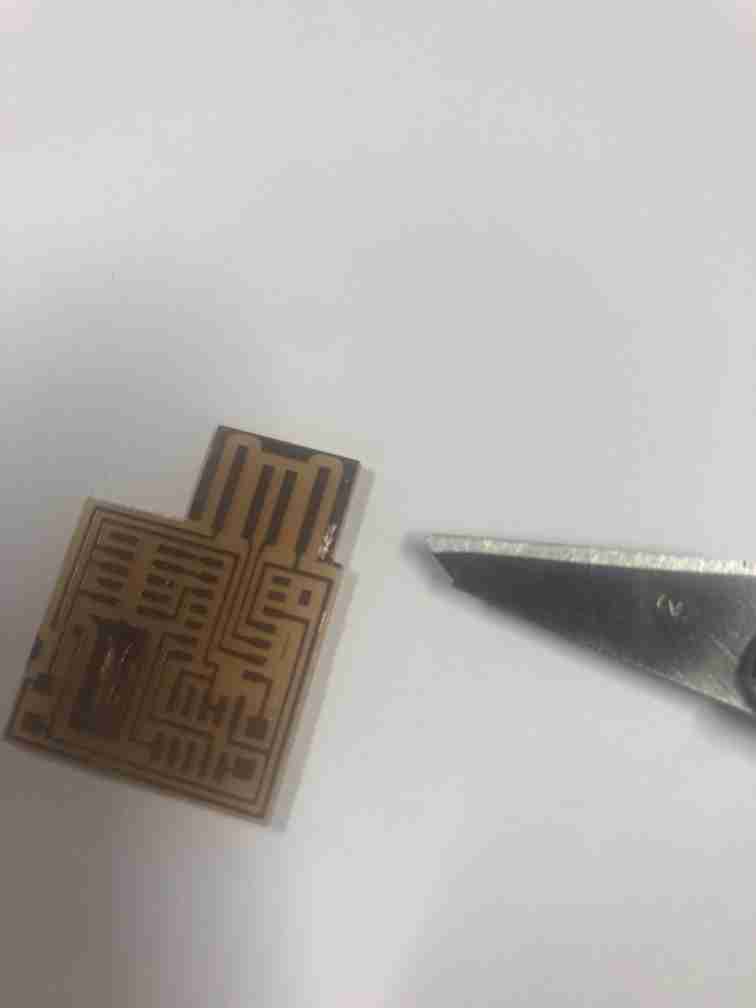
you may be obliged to manually remove some copper, to avoid shortcut