This week, I had to integrate an output device to a board made by myself. Instead of continue doing small boards for each week, I decided to create my final project board, prototype it and because I had many time, send my board to JLC PCB to have a very high quality finish board. However, this was not the original plan. At the beginning, I wanted to create my own ESC, which I very soon saw that was a work for a longer time period. I worked on this project for like two weeks, having good and bad moments because at the beginning I managed to make the motor rotate a bit but very soon the board that I made in a kind of permaboard, just broke so I had to make another one, that for some reason never worked. After talking with Neil, I decided that I had to buy my ESCs but I am more decide than ever to build my own ESC, and make it 100% open source because really there is no information about them on internet.

I think that one of the biggest challenge of the ESC design, has been the lack of information.
There were not a lot of information about ESCs of the FabAcadmey files.
I searched for some other people that was building an ESC and I only find one person and really,
it was useless for me because it was a project for a much smaller engine but if you are building a small drone for example,
you can really use his design which looks very well
FabAcademy ESC.
Neil told me to use A4963 which is much better than the A4941 because in this case you are able to put the mosfets you want (the A4941 has mosfets inside but can only deal with very small bldc motors).
The components that I used are:
3x N Mosfet, I am using the IRF540N.
3x P Mosfet, I am using the IRF9540.
1x 470uf - 35v capacitor
1x 10⁴ ceramic cap
I am using a 24V, 10A power supply
Download A4963 Datasheet

For the first prototype I used a kind of permaboard to make the connexions. In the documentation of the a4963, it is suggested to use a current limiting resistor to limit the amount of current that goes to the motor.
However, I had not such a small resistor, so I decided to connect CSP and CSM to the ground which is also explain in the documentation but in this case, it does not limit the amount of current. After making that,
the motor started to turn but with difficulties. However after some time testing, the connexion between the gate of both mosfet broke and I decided to rebuild the board but with better connexions.
Also as you see, I made a small board to solder the a4963 and which has pins to connect it to your power board.
A4963 Sketch
A4963 Board

For the second prototype, basically I made two main improvements. The first one is that for the power board, I only used tin for the connexions and to connect it to the control (a4963), I used screw terminals that in my opinion are much more trustable. But for some reason, here I have never been able to make the motor move. Even if as you will see, the output signal looked nice. When measuring the voltage from the ground to each gate, I had 24 volts but the problem is that between phase to phase, I should also have 24 volts but I had nothing.

Thanks to a potentiometer that read the signal and translate it to a pwm signal that I later send to the a4963, I was able to change "the speed" of the motor. In this case you can see the waveform at the end of each Mosfet gate. When the period is smaller, we should go faster. You can also see the peak to peak voltage that is nearly 24 volts.

A nice other thing about allegro, is that they have a webpage with lots of information, in which you can also find an app to control your a4963 with an ftdi cable.
In my case, I was not very sure about the programming, so I really appreciate this app because at least you are sure that the chip receive all the information you want.
In this website, you will also find an example board where you can see which resistors you have to put between the chip and your FTDI cable.
Here is the link for the demo board.
Here is the link to download the app.

After two weeks working on my ESC, I really had to make an Output board, so while the ESCs arrived, I started the process of design of a board that could control everything on my Longboard.
But really at this moment I was not very sure about the functionality that I wanted to give to the longboard (so to the board).
A couple of days later, I decided that I wanted to be able to connect my two Brushless motors, an RGB LED strip, two FSR (force sensitive resistor) and all that controlled by a bluetooth module.
As always, I had to be able to upload the bootloader the first time, so an SPI connexion was obvious, as well as a serial connexion for the FTDI cable.
At the beginning, I decided to base my design on the SatshaBoard, but very soon I saw that it was going to be useless because my Pinout was completely different.
After thinking on how to power the whole longboard, I decided to use a 6S3P battery pack (made by myself),
so I had to add a circuit to measure the charge percentage of the battery and also some voltage regulators to power the microcontroller and also the LED strips.
I made some simple maths to know the value of my resistors:
Vo=Vs x R2 / (R1+R2) → 25.2=Vs x 5k / (100k+5k)
Vs=1,2V
Because the Internal reference is much more precise for the analogRead, I am transforming the 25.2v that is my max input voltage to 1,2V to compare it with the 1,1V of the Internal Reference of the 328p.
Also you can see a Zener Diode to protect the microcontroller if the voltage is higher than 3,3V.
Download Sketch
LED Circuit Inspiration
Battery Charge Circuit

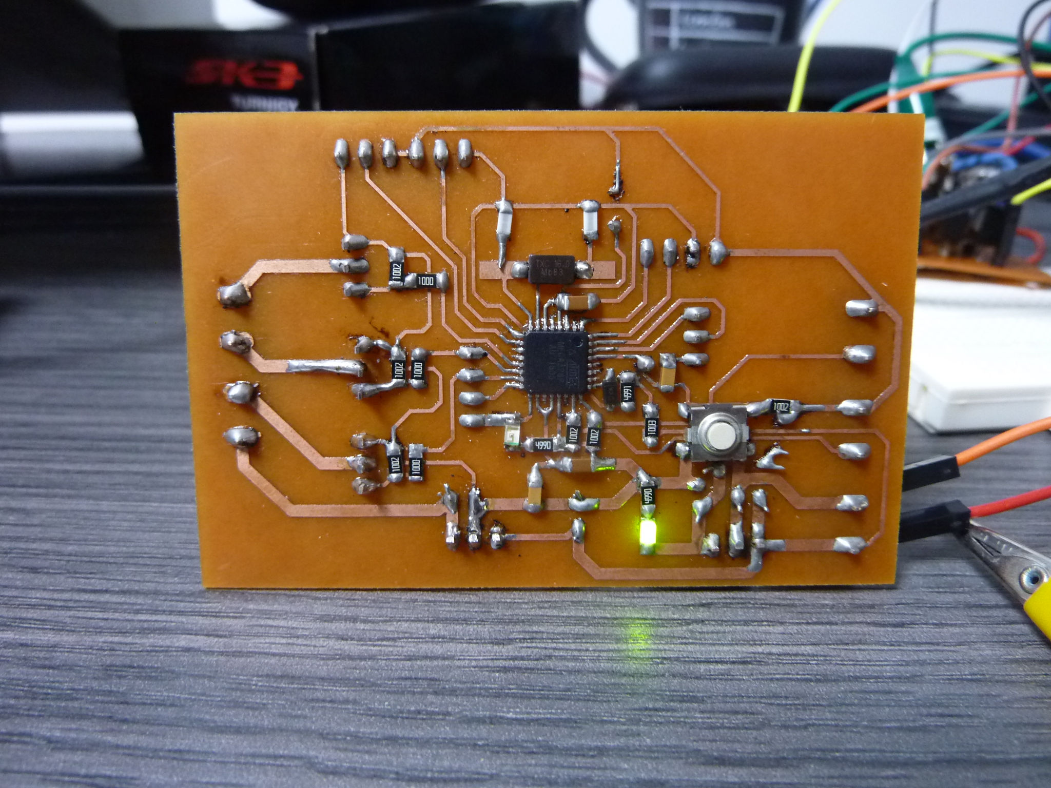
Finally here it is, after nearly two days of design my board was ready to be tested for the first time.
The design looks very nice even if the FTDI and SPI are not put with the normal shape, so I will have to use jumpers wires to connect them to the board.
Later, I will understand that the worst idea I ever had was to put the reset pin of the SPI alone because it is not that strong and I will very fast have problems with it.
As you can see, I am using through hole components so my board will have two sides.
The reason why I am using those components, is because we didn't had them on SMD, but I will buy at least the mosfets in an SMD formfactor for the final board.
Download Board

For the first time since I am doing the fabacademy, I decided to use the -1 offset because I wanted to have a very clean board to make it easier to solder all those components.
The others parameters are the same as always but this time I am using the 0.010 end-mill: 3000dpi, 4500rpm, coolant off/ your tool number, cut depth 0.15mm.
The process took a while because as you see, there is plenty of traces to make it clean.
Because I know how long this is, I leave you here the .nc file already generated.
NC - Offset -1

The milling process, has to be as always very well execute if you want a good result since the first try. The first step is to clean both side of the board with some alcohol to remove the dust. After that, you put the double tape and you fix the board very well to the Rolland. If you see that the board is buckled, you can try to make it straight with you hand of a rubber hammer. Once this is done, you configure x0, y0 and (z0 in the middle of the board).

If you thought that one hour waiting for FabModules to make you Gcode was a lot, well this process took nearly 6 times more. The milling process was that so long that I decided to leave it working during the night and really I don't know how but I had a very good result since the first try. After that, the outline process took like 5 minutes and I had my board ready to make the holes and solder the components.
")
One of the negative points of using through holes components, is that you have to make the holes, and for some reason, I have never been able to automate this process, when I try, the Gcode make a first cut around the border of the holes, making them too big. It is for this reason that I use the Dremel with a 1/64" end-mill and a bit of practice to make the holes.

As I should have expected, the reset pin of the SPI, just broke and separate the copper from the board. It is for this reason that I used a cable to rebuild the trace and resolder a pin of that cable to program the board. Once programed, I desoldered this pin.

Because of the Reset Pin and the center Mosfet connexion that was very weak, I searched in internet if the hot-glue was bad for the electronics, and I didn't find any mortal comment, so I decided to put some hot-glue on those part to protect them, and made them stronger. As expected, the board continue to work as it should and now the fragile parts are completely protected.

The connexion of the ESC, is very simple, the three phases, doesn't have an order, so you can connect any of them, with any of the motor phases because thanks the current back detection, the ESC can know exactly in which position the motor is. After that, you have to power the ESC with 22-24V and at least 4-5 amps. Finally for the control, we will only use two of the three pin that the ESC has, because we only need the ground (brown) and the PWM pin (yellow). In my case, I received the ESCs after I made the board, so the order of the pins was not correct, reason why I am using jumpers.

Even if in the code you are seeing the motor and the LED strip working together, I don't post the code yet because it is part of week 14.
Basically, here I am testing both in an individually way. When I made the board,
I didn't had the RGB LED strip yet to I just tested one by one my outputs with a white LED (if each output works, it should works with the three at the same time).
So basically, the LED code consists of 6 lines of code, I initialize my three outputs pins, and I send a different pwm signal on each digital pin to create a different color.
For the motor, you have to use the library Servo.h, to initialize a Servo Object and be able to control an ESC.
For some reason, the Servos use the initialization process than a ESC (it is not enough just to send you PWM signal, you have to initialize them).
After that, in my case I am using the serial monitor to send a value between 1000 to 2000 to control the speed of the motor.
If you write 0, the motor will switch off.
Later I will better understand how the ESCs are programed (how to create an acceleration ramp, deceleration ramp, min-start-up power, etc...).
If you want to control two motors, it is the same but two time basically, however you will need the info gave in week 14.
ESC - CODE
RGB LED Strip - CODE
")
Well after mapping some pinouts errors, some ergonomics error, and some aesthetics errors, I decided to rebuild my board and this time, to send it to JLC PCB to have a final product kind of board. Even if I feel that Later, I am going to want to change it again. This time as you can see, the main differences are the two gigantic heatsinks for the two voltage regulators that after one or two hours working, start to be hot. Another important change is that this time I added the correct pinout for the FTDI and for the SPI connexion. The new board will use SMDs Mosfets because the other ones, are not the ergonomic and cant really dissipate the heat. Finally some small corrections as the pinout of the motors and a voltage divider for the HM-10 bluetooth module but we will talk more about it in week 14.
For this group assignment, we had to measure the power consumption of an output device. In this case I decided to measure the current of my BLDC without any resistance (mechanical resistance). To calculate the power, you have to multiply the current and the voltage. In my case the current arrived to nearly 1 Amp, and the voltage was 23.5V. So if we multiply, we obtain that the power consumption is 23,5 Watts.
My board controlling a BLDC ESC and a LED Strip.
Please Contact Me For Any Collaborative Project