2013 project
Back in 2013 I never re-designed any of the boards that we used as I got stuck in the world of Electronics Design - and never recovered from that. I did however, program the standard boards that can be found on the FabAcademy website.
What I said about the boards:
As we knew this week was coming, we (Bjartur) already milled out some of the original boards. The only thing that we had to do was simply assemble and solder the board and program it. None of us however redesigned the board that year.
On the programming of the board I mentioned that I got stuck at first but got some good info from Bjartur and seemed to have found a descent site to help myself out. The site can be found here.
Looking back at his documentation and my own documentation back then I understand why I never finished the academy. Though, instead of being angry at myself for the things I made or didn't make back then, I have to remember that my knowledge about electronics was far less than nihil back then. So hey, look at that learning curve!
What I said about programming the board
The only thing worth mentioning at the moment is, how I managed to program my boards back then. But even now I don't know how if this still applies. I guess we'll see it by the end of the week.
- Make sure that you have all the necessary documents (make and rx.py) and that you know where they are. Go to that place in the terminal (cd Desktop)
- sudo make -f hello.light.45.make (this is the file that belongs to the board: hello.light, hello.sound...)
- sudo make -f hello.light.45.mak program-usbtiny (This is one way, Mercedes describes both)
- You need to find the gate where your ISP is plugged in. => ls /dev (make sure for the space between ls and /)
- type: python rx.py /dev/ttyUSB0 (make sure that you have the right file name and ttyUSB0 is the gate where the ISP and my computer were connected. This can be different from yours, to find out the gate: ls /dev)
That week I managed to make the boards work with Neil's code and actually measure something. Why retaking the week? Because 1) The documentation sucks. 2) We never redesigned the boards ourselves. 3) I - once again - lost the files.
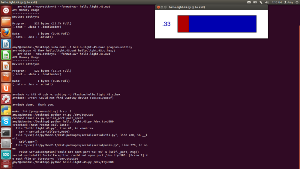
 The result from the hello_temp board in 2013
2019 project: fidget spinner
So for this week we needed to have a board that could measure input. Having heard about all the sensors that exist that can register input, I decided to go with a tilt switch.
I looked around in the lab (and asked Cristina for help to find it) and she gave me some components from a electrical fidget spinner. Thought the hype is over by now, the board didn't
look so complex and I decided to redesign this for my input week.
 The components as I found them in the lab
So, first things first, this time I didn't have to go on an expedition within the electronic component boxes as I already had everything in the kit. But, there is always a but.
- The components that I have don't have the serial numbers on it again.
- The packages are different
- 1206
- 1806
- through hole: the tilt switch
Previous exercises learned me that a 1001 block would probably be a 1206 resistor. I checked with old board that I made during the academy, and they line up. For every component in the package, I had to go and find their function - knowing that there would be components in the kit that I have never seen before.
This one was interesting, and I didn't anticipate it until I started going though my eagle libraries to find the right component. But so far, the kit exists out of 3 different packages.
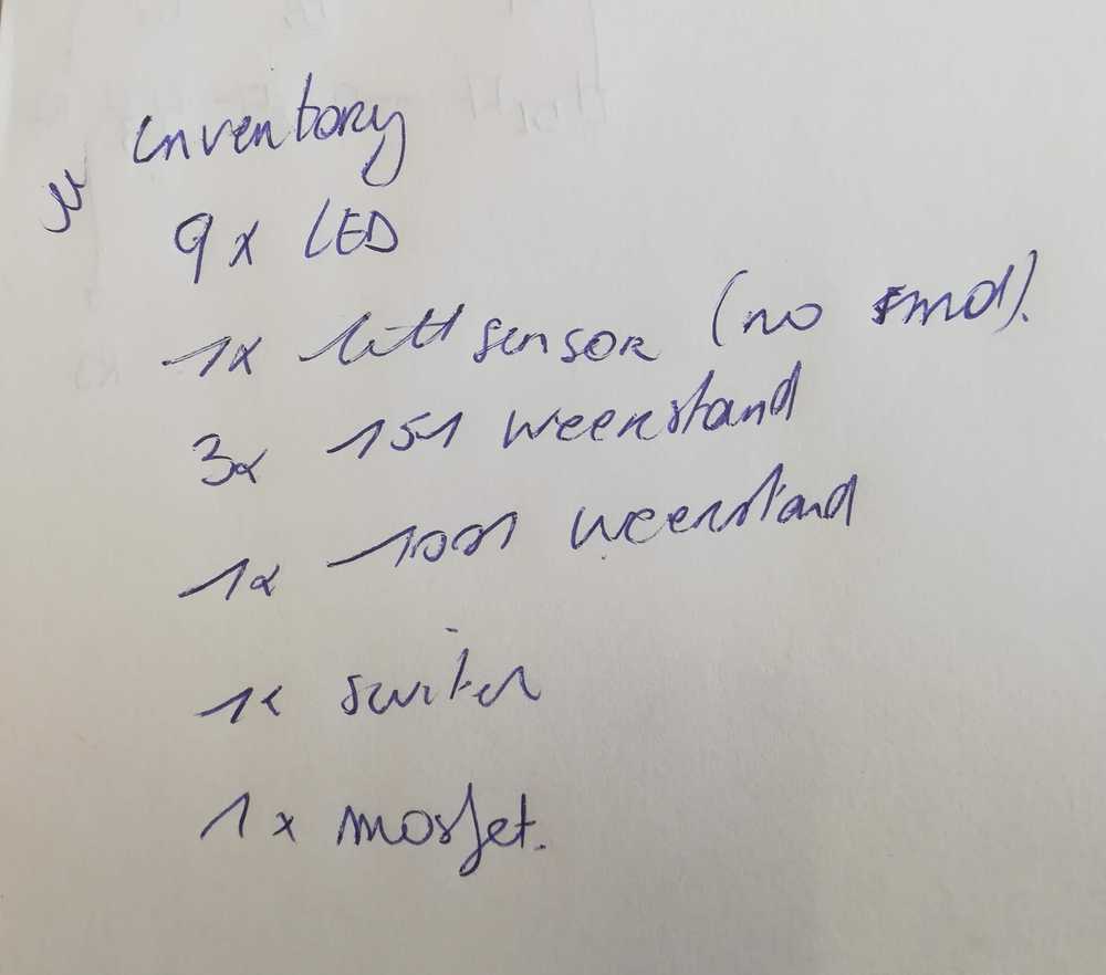
The next step for me was to make the full inventory of the components that I needed, knowing that they might be from different packages. Just to have a checklist.
- 9x LED (1806 SMD)
- 1x tiltsensor / old version, new one is called 'hall effect sensor'
- 3x 151 resistor (1206 SMD)
- 1x 1001 resistor (1206 SMD)
- 1x switch
- 1x mosfet transistor
- 3x coin cell batterieholder
- 3x coin cell batteries
- 1x PCB / redrawing this
- 1x bearing
 As a extra for this project I decided to make my second version with components that all belong to the same package.
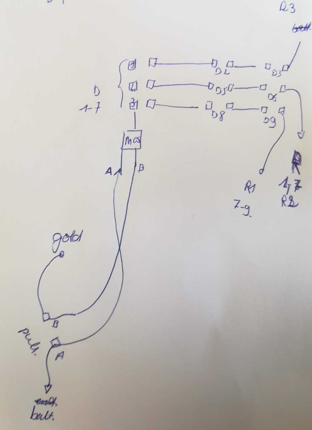
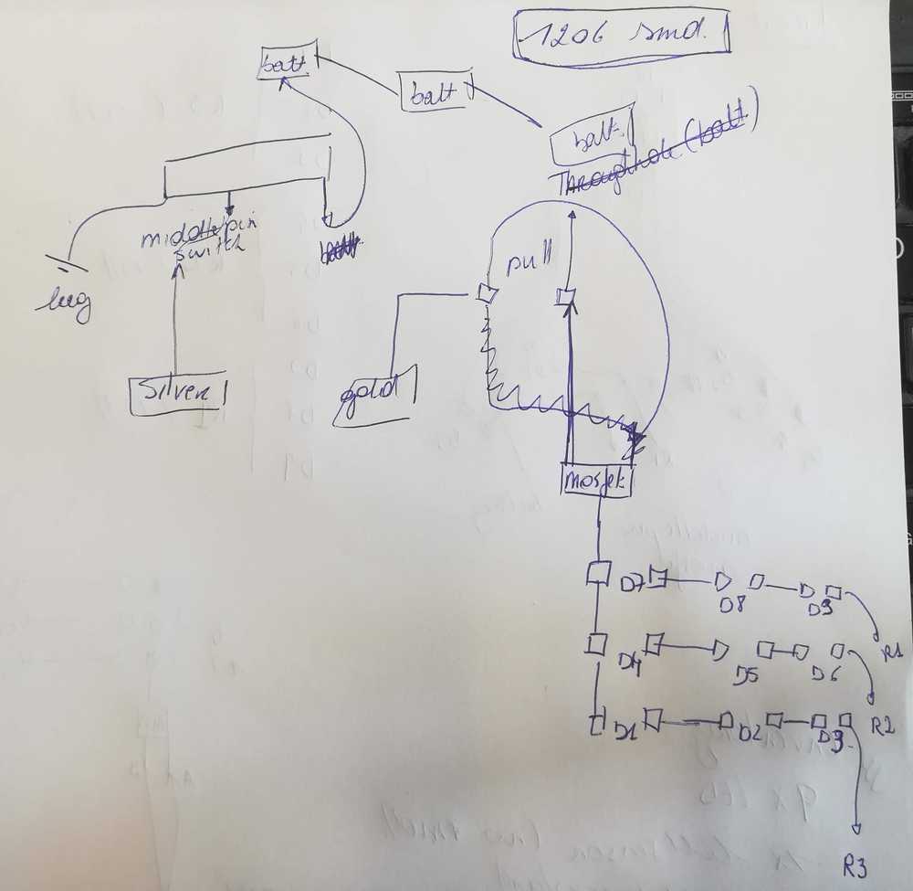
Now that I knew about my components, I started figuring out how the original circuit works. It might have looked easy: some led's, a battery and a switch. The thing is, the original
part is through hole! I've never done a through hole PBC and following the lines wasn't as easy as I thought. So I started sketching and after about 45 min, I had a complete sketch of
the circuit with everything that I needed to understand! The circuit was memorized and ready in my head to start drawing in eagle on the train the next morning.
 First sketch trying to understand the circuit
 Second sketch of the circuit
 My last and good sketch
This last part went significantly faster than the past weeks and soon I found myself with a board for the circuit. The only problem I ran into was the tilt switch. I didn't know
how to search and find that one in the eagle libraries so I called in help. Only to have the reaction: Sorry, that sensor is obsolete.. Hah! Okay then.
While talking about the sensor, I also realized that there was another 'problem'. There is no micro controller on the board! Guess the assignment gets gradually more and more difficult.
The thing with the micro controller was that there was no micro controller on the board... But it is something that's needed here, in the FabAcademy. So, off to a new drawing.
Final project progress
During this week I also found some time to work on my final project. Some of the materials that I wanted to use for prototyping the giant breadboards arrived. So I spend time on that. More info can be found on the Final project development page.
Interesting however was that I managed to draw the PCB that I'll use for the final project (update June 2019: it changed later on). It took me a while to figure out because I had problems with the schematics and finding the right components. As mentioned before, there are several packages and a ton of components. As I started this in the 'electronics design week', it still took me a while to figure out how it would all connect. One of the problems that I'm starting to notice is that I simply don't have enough basic knowledge about electronics to design PCB's. I can make circuits with children, and help them out on the basics. But once the other components join (read: everything except LED's, DC motors...), I'm lost.
While googling, and talking to other people about electronics they mentioned (and confirmed) that you can find a lot of information on electronics for intermediate and advanced knowledge, but barely anything for newbies. As I was designing other boards and making more mistakes, seeing where my first documentation is failing me, I started making a manual for beginners in Eagle. Just enough for the basics, to have your PCB's going. What the numbers mean, what everything does. But not to much extra's. The rest can be googled later. But there is a need for a basic, clear manual for eagle. By now it can be found here!
Anyway, back to the board. I didn't finish this week in time and as time passed, my idea for input and output changed. I ended up with the full extent of my final project and what I needed for electronics in it. My eventual input and output are basic. LED's, buttons, switches and a tilt switch. Nothing more, pretty "basic", but good enough for a beginner like me and for the children. I honestly prefer to get the basics right and understand everything that I'm doing than to rush things and make awesome pretty boards but not understand a thing of it.
For this week I made a board with 2 LED's and the tilt switch. It sounds basic, but it gave me the time to figure out how a tilt switch actually works. Because, it ain't just all about the angle.
Update end of the academy:
As you noticed after deciding what needed to come onto the board, I kinda left this assignment for what it was and moved on to other assignments. The result is that the input and output week got integrated into the other assignments and final project. I seem to have liked to put all the electronics in one big assignment
The idea is still the same, LED's, tilt switches, but now connected to interfaces and networking. Anyway, at some point I needed to come back to this assignment and finish it up.
I made the final board before finishing up the input and output week, but that didn't mean that I didn't - well let's say it cruel - fuck it up. The board is easy enough, but the soldering isn't. Note for the students next year: psst, reflow oven.
The problems started when I wanted to solder the 330R resistor. I hit one of the other layers and seem to have soldered them together. The same happened with 2 pins of the micro controller. We tried so salvage - called in the help of master solderer Cristina, but nothing could help. Another board lost. Luckily for me, I have my etching materials in my car and could make a new board.
Another strange thing that happened is that one of the LED's just disappeared. Not the whole block, no, just the little bowl on top of it. Murphy and little brother/sister jokes incoming. But I'll just go with: "my cat chewed on it and broke it." Were not sure what happened to the LED, but well, we were making a new board anyway.
The code
The code for this assignment was made - as usual - in Blockly. In the code you'll find the part where I declare the push button and what it needs to do. But basically what it does is the same as in the hello world board. If you push the button, the lights go on. The special part that got added is the part where the tilt switch comes in. My input sensor. The tilt switch only goes on when you... tilt the board to one side or the other. Inside the switch (it are old) is a small ball that makes contact or doesn't make contact.
In summary
The board of the input week does 2 things:
- If you push the button, the 2 LED's start burning
- If you tilt the board a third LED starts burning
- Fidget spinner and final project got merged
The in put here is the push button, and output the LED's
As extra input I used a tilt switch, but made it like that that you can change the input sensor. If you tilt the switch the little ball inside the switch goes rolling and puts a LED high or low. I specifically used an old tilt switch because those are the easiest for kids to understand.
As you noticed, I started talking about a figdet spinner and how to develop that one myself, and then I went on to the final project. Somewhere along the way both projects got merged. Reading the input even happens in the networking week.
Hero shot
Manuals and files
Eagle files for input - output week
Code files for input - output week
