-
Part I: Problem description
Part II: What has been done before?
Part III: Materials
Part IV: Prototypes and testing
Part V: Breadboards for the children
Part VI: Breadboard for the teachers
Part VII: Lesson-plans for (advanced) electronics
Part I: Problem description
During the past months I had the honor to observe several workshops about< micro-controllers given by Ingegno. And there were a few things that caught my attention
First of all: out of children (and adults that are new to this) might be overwhelmed the moment they see a breadboard or micro controller in front of them. Especially if they never
came into contact with a micro-controller before.
Second: a breadboard has a lot of small holes where you pin the jumper wires in. Even though the teacher in question was using pictures that were being enlarged due to a projector,
some children still found it difficult to follow where the jumper wire needed to be added.
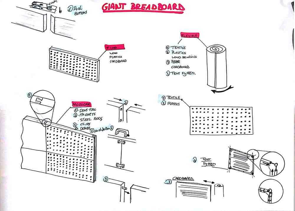
The Ingegno Makerspace feels that teaching microcomputers to children and adults can be quite demanding due to the small insert holes of the breadboards. To make this more easy and understandable they have asked to develop a giant breadboard with working components to explain the basis of physical computing to children and adults.
Next to that, Ingegno also uses their self developed LED up Kidz. As this is still one of the first versions, it is time to make the design a bit updated and review the project. In the end we’d like to combine the giant breadboard with the LED up Kidz.
What
A giant breadboard, including components that can be used to teach children about micro-controllers. The teacher gets a giant breadboard that can be used as a board, but also the children get a bigger than usual breadboard.
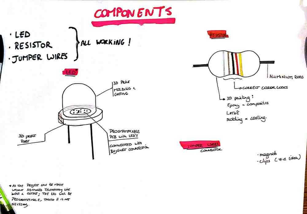
The second part of the assignment is to make giant components, that work. For now we keep it down to 3 components: a LED, resistor and push button.
The last part of the assignment is to adapt the LED up Kidz to the breadboard - or the other way around. The LED up Kidz is a workshop that we give to children aged 8 tot 14 to learn about SMD soldering, electronics production and programming.
Where
Most of the prototyping will take place in the Lab in Drongen. As Amy is connected to the FabAcademy, most of the electronics will be produced there.
How
During the development of the project, we’ll use several known prototyping techniques like 3D printing and laser cutting. But we’d also like to use some time to test out new things. For example textile and electronics, or DIY projects combined with high tech. For example. A lot of sites and companies are swearing with conductive ink or paint. But or, it arrives and doesn't work, or it dries out to fast. What if we combine making our own ink with high tech electronics like a breadboard made with it. Or combine our conductive paint with textiles.
To top
Part II: What has been done before?
And what can we learn from it?
When I got the question to make a giant breadboard, my instinct was to open a search engine and look up what already exists. There were 2 big players online: Sparkfun, OSH Park and Hackaday
Sparkfun
The SparkFun video was not only fun to watch, but also interesting. As they are making a time lapse, you can clearly see all the materials that they used.
Pro
- Basic materials (isomo, metal plates, wires...)
- Clear building instructions
Con
- Where are the giant components? Note: we found them much much later
OSH Park
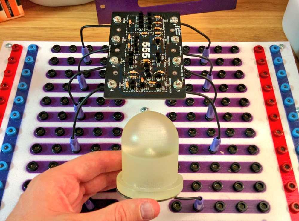
During my search I found a tweet form OSH park and the fact that they made a giant breadboard that looked quite resistant to children. We looked further into it but we didn't find more
info on it. We reached out on twitter, but only got info about the 555 kit and nothing about the board.
Turns out this will be look and learn documentation.
Pro
- Clear and understandable
- Good connections to the breadboard
Con
- Only documentation is the twitter-tweet
Hackaday
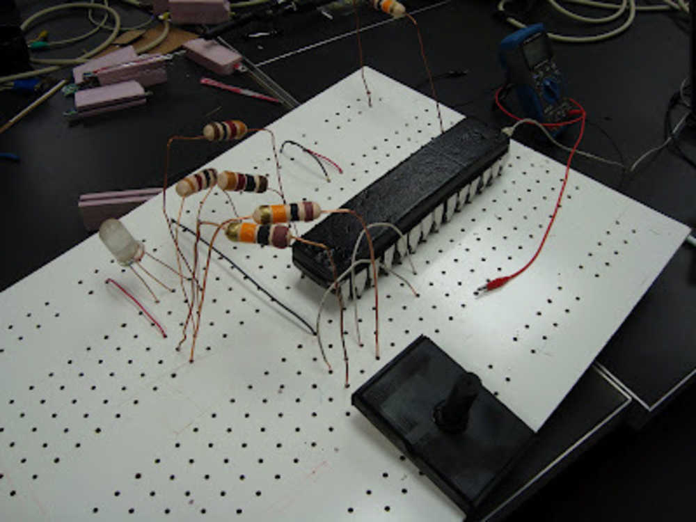
The search also led us to the hackaday website. They have an article about a Minneapolis/St Paul based hackspace that made a giant breadboard. Sadly it only stayed at one article and some 404 links.
Pro
- A useful picture.
Con
- No extra information
To top
Part III: Materials
Before we jumped to making prototypes and testing with children and teachers, we first needed to learn about the materials that we had in mind. Below you can find a list of the materials that we tested and could possibly use.
- conductive ink
- conductive loop and hole (read: velcro)
- conductive textile
- standard materials
- magnetic plates
- thin steel plates
Conductive ink
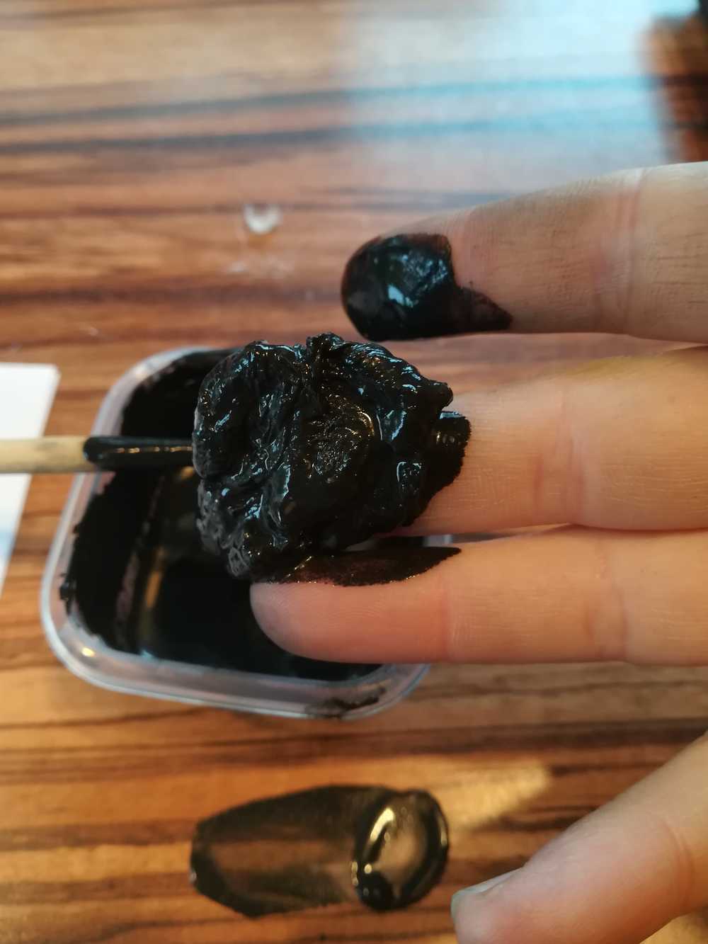
I've spend a lot of time on this ink. Trying out different receipts but never really having the low resistance that we wanted. We did however end up with a good ink that we can use for workshops and temporary projects. I could talk you through all of the tests that I did, but you might aswell look here. This is the page that I started when documenting the final development, but decided to change.
Conductive loop and hole (read: velcro)
On the way!
Conductive textile
Conductive textile is an interesting one. For now I split this up in 2 parts. One part is the actual textile the other part is the Beckaert wire, a type of conductive wire.
I started using the Beckaert wire during the lasercutting and vinyl cutting week.
Standard materials
Within standard materials I enclude common materials that you can find pretty easely (in the western world). In this part I'm specifically taking about aluminum tape, copper tape... The materials that you can easely find in a FabLab, Makerspace or normal hobby store.
Magnetic plates
Thin steel plates
Part IV: Prototypes and testing
Of course a project and prototyping doesn't just happen like this. So of course prototyping is a must, just like testing. For the ease of overview, I'll split this part up in several smaller parts: making the jumper wires, making the boards, making the colored plates and many others
Testing the conductivity of the materials
As mentioned before, we worked for a while on conductive ink. This also ment that we had to test the conductivity of the ink and see if we got the same results as with other materials. Next to that, making one LED burn is often easy, but more complex projects might not be.
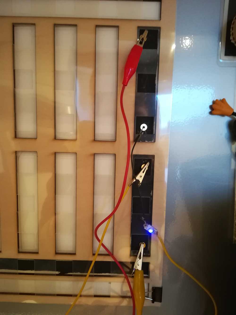
I decided to make a general test plate and give each line on the breadboard to another material. Or open for a next, still to discover material. As none of the first 3 materials that we tested shared the properties of conductivity and magnetism, I needed to find a solution for this. The solution was found on the photo wall at my parents house: a magnetic plate! We soon deceided to not work with a giant plate in the back, but with smaller strips of magnetic material. This led to the new materials that we tested out.
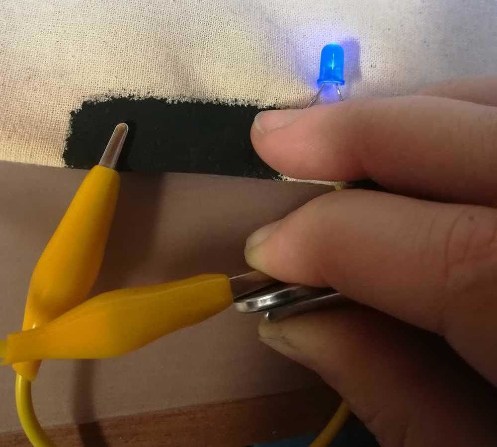
 Test with conductive ink. The LED is not burning bright due to a to high resistance
 Test with copper tape
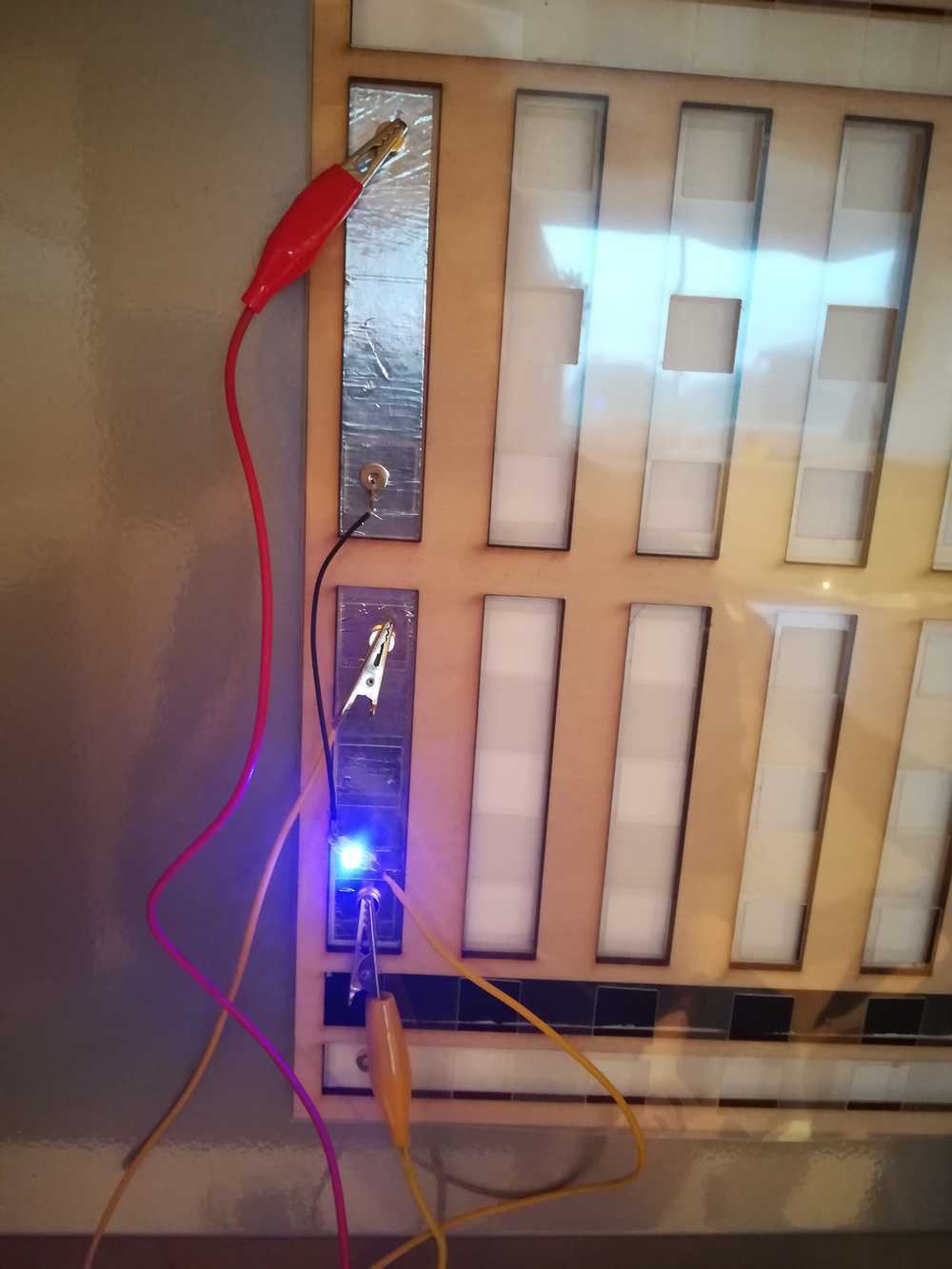 Test with aluminum paper
To top
Making a small prototype to test
Keeping material cost and time in mind, I started making a small prototype to test out all of our options. A full description of the tests can be found here. The
results came down do: use stronger magnets and get enough magnetism from the back layer.
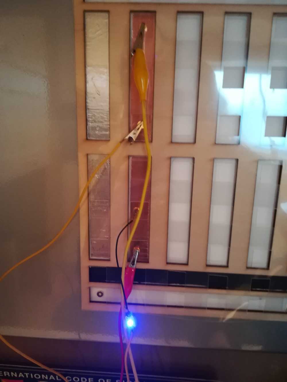
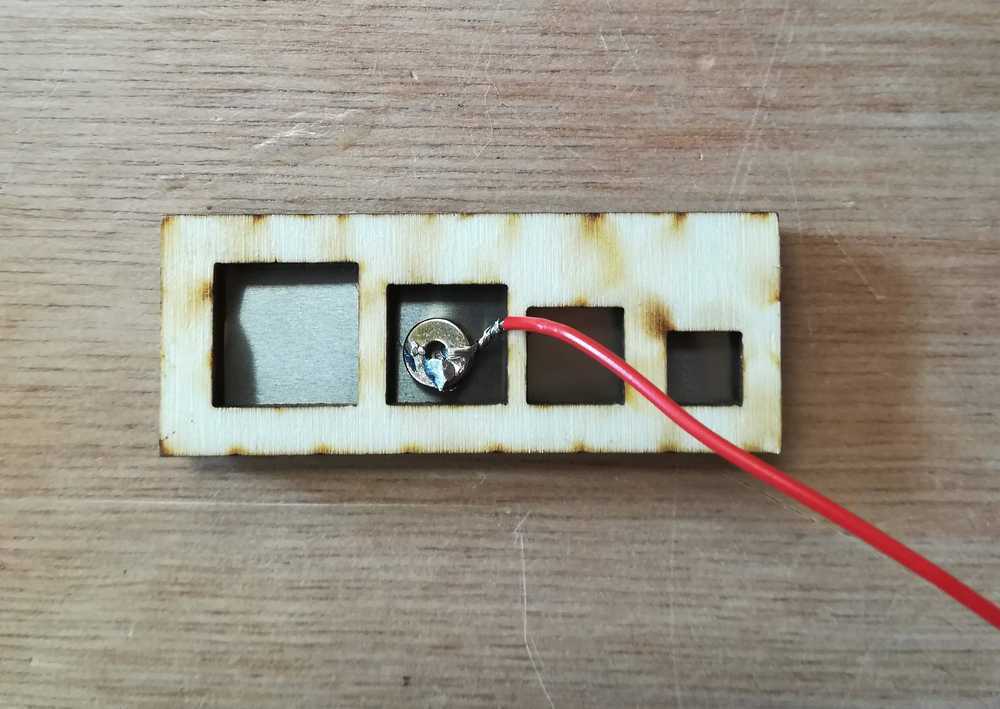
In the picture below you can see a test that we conducted with small steel strips, filt, PVC plastic to show the holes, magnets and wires.
We didn't connect the wires the right way as we were just testing the connectivity and resistance at that moment.

Another thing that needed to be tested was the size of the holes. I made some samples and asked the kids in the lab wich one they prefered. We settled on the 2 biggest ones.
My biggest mistake during the tests? Soldering the magnets to the wire. They can be soldered, but you need a very specific technique for it - that I eventually learned. When heathing up a magnet, it loosed a part of their magnetic force. The new problemassingment for the jumperwires would be this: How to connect wires to the magnets without soldering or glue?
To top
Making the jumper wires
Machines used: 3D printer
Tools used: stripping pliers
Components used: magnets, electrical wires
The first thing that I needed to do was to fix the 3D printer as it did not print perfect circles.
The second step was to design the part in Onshape and print it out. Ofcourse, you need to keep tolerances in mind and the electrical wire also needs to fit.
The third step is to prepare the wires for assebly. You can do this perfectly while waiting for the printer. Take some electrical wire and cut it of at a distance that you know can cover the breadboard. Make sure to take some extra as you'll need to wind it around the magnets.
The last step, is the assembly of all the parts. You have wires, magnets and your 3D printed components. Take a 3D printed piece and slide it over the wire, now connect the magnet to the end and push the magnet in the 3D print. Do the same for the other side.


To top
Making the colored guide plates
Machines used: vinyl cutter
Tools used: surgical knife
Material used: plastic
If you cover up the connections, they kids once again loose track of the connector lines within the breadboard. The solution for that is or opening up an existing breadboard and showing this to the kids. But that is what we do now and it only has a select impact on the children. We really wanted to bring the breadboard to them and let them experience the connections. Seeing the wires, combined with how we explain conductivity, might be the solution.
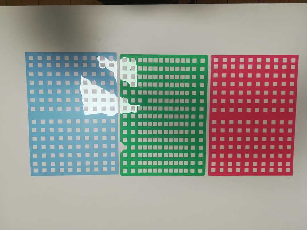
I started with a drawing in Inkscape, the same that I've been working on for the other parts of the breadboard. The outlines stayed the same, but the inside changed, because in this case I only needed the small holes.
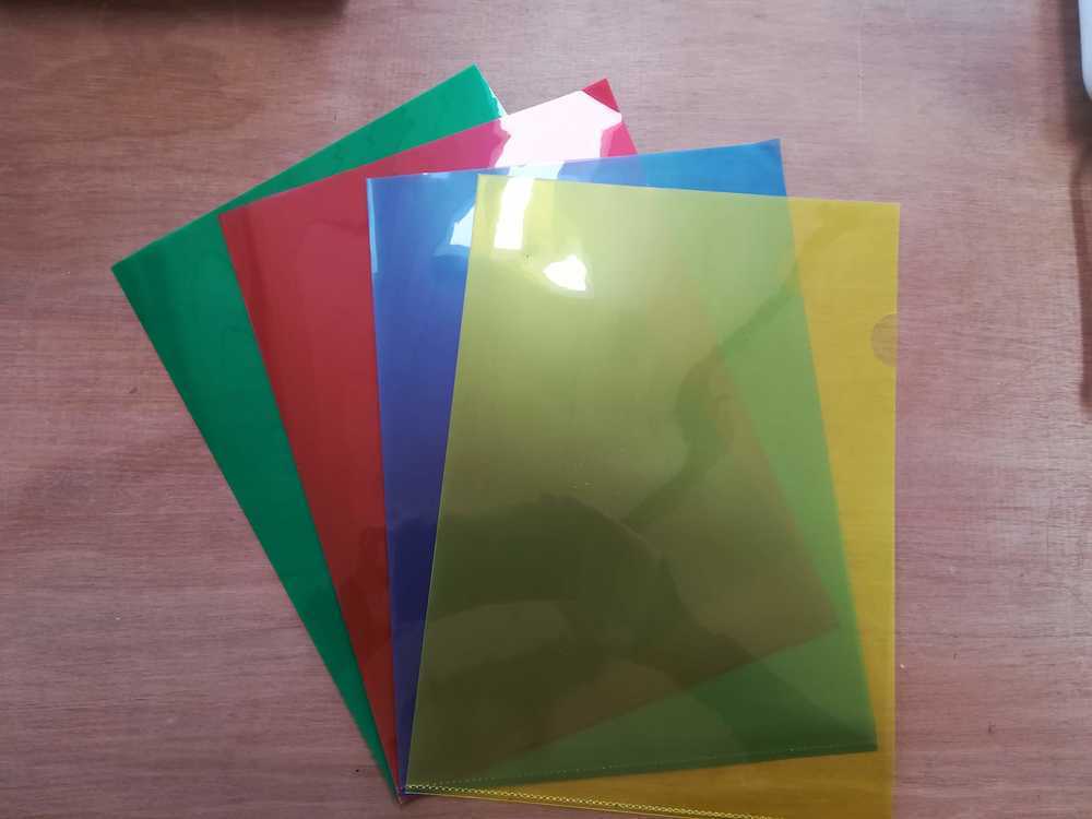
As for materials, we chose to use normal charts in which you can put paper. Sadly, the material wasn't specified further than just 'plastic'. I still need to find time to do the burning tests to determine if the plastic is actually ABS or PVC. But for now I went with putting the material in the vinyl cutter and cutting it that way.
Interesting to see was that not every color cuts the same. Blue and red were the best and easiest to cut, green and yellow were a mess.
To top
Making the wooden plates
Machines used: lasercutter
Tools used: surgical knife
Material used: multiplex poplar wood (4mm)
During the tests on your first mini breadboard we learned that the magnetism isn't always going down. So we needed to find a way to keep the magnets and jumperwires seperated. We set a step back to the first A4 prototype that I made and changed the drawing a bit so that it would fit the new layout. It turned out to be a hit. The magnets stayed seperated from each other.
To top
First user test!
As Easter approached, so did the holidays and the possibility of testing the breadboard out on about 20 children (in 2 groups). I rushed to finish the test breadboards (leaving the other assignments of the Academy for what the were) and delivered. The reason why we did a user test was to define if the kids could:
- Work better with the breadboard
- Understand better how the board works
- Still have fun
- the system we have now is a good system
- The magnets are strong enough
- The materials hold the abuse of children
Conclusions
There are two main conclusions to take after this first stage. First of all: working with magnets will be harder than anticipated. Second the produciton process needs to be optimised.
The magnets and magnetic part of the breadboard already got expained a bit before. But here is a recap....
What we didn't talk about yet is the time it takes to produce the breadboards. Machining time is always being counted differently for me. You might need the laser for an hour, or the 3D printer, but you can do other things while waiting. But during the assembly, you need to be focused on just that. Some notes of attention:
- Check the colour of the plastic. Some plastic cuts better than other. This gives you less or more work
- Check the static electricity on the plastic. The green plastic was a mess as it got stuck to everything due to static electricity. The other colours however (escpecially red and blue), just poped out.
- Lasercut the filt and put markings on where the conductive/magnetic parts need to come. This time I always put some lines on the filt to see where I had to put my pieces, but its not completely exact. It will save time later on to not having to recheck everything if they are lying good.
- Use a different adhesive for the steel strips.
- Optimise the whole cutting proces of steel trips, magnets and conductive textile See what you can lasercut or make a mold. This will also help if all the pieces are the exact same size.
- In the landscape models, create some more space for the underlying lines.