-
Why the electronics
The board design
The components
Programming the board
Hero Shot
Next steps
Files
Why the electronics
The first reason is that we needed to include electronics in our final project. I could perfectly fabricate everything for the Giant Breadboards in the FabLab without
putting a PCB inside of it.
At first I thought to have micro controllers control the giant components. But then I figured out that it's easier to just put them inside.
I could also just have found another project to do, but I was motivated for the giant breadboard so I stayed with that.
Another reason to add electronics is that we wanted to change our LED-up Kids anyway. It could be a good practice to start from an existing prototype to adjust it and make something new. In the end, something similar happened. I started from the original LED-up kids and an electronic fidget spinner, only to end up with my first actual board.
Of course it didn't just became a board as we'll put it to use in the workshops that we give around electronics.
To top
The board design
The full workflow of the board design and troubleshooting can be found through the full course of the FabAcademy, but mainly back in the Networking week. But I'll give you all the necessary pictures here.
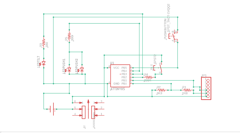 Schema of the final board
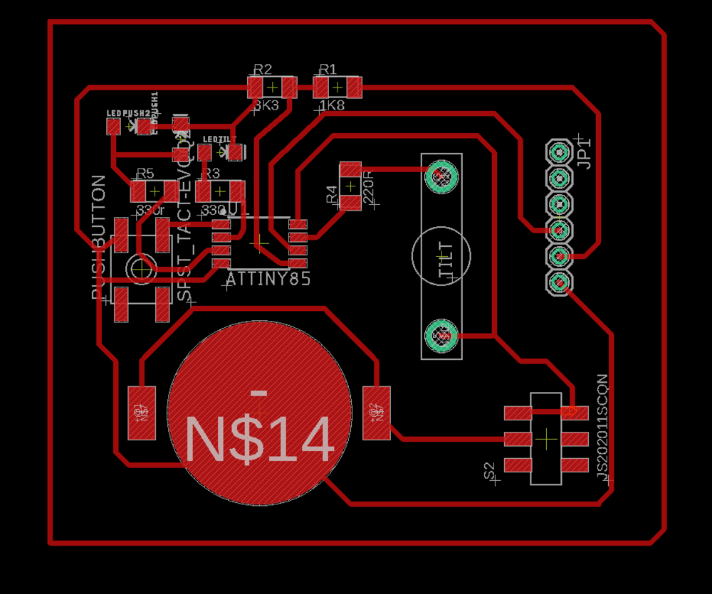 Board in Eagle of the final board
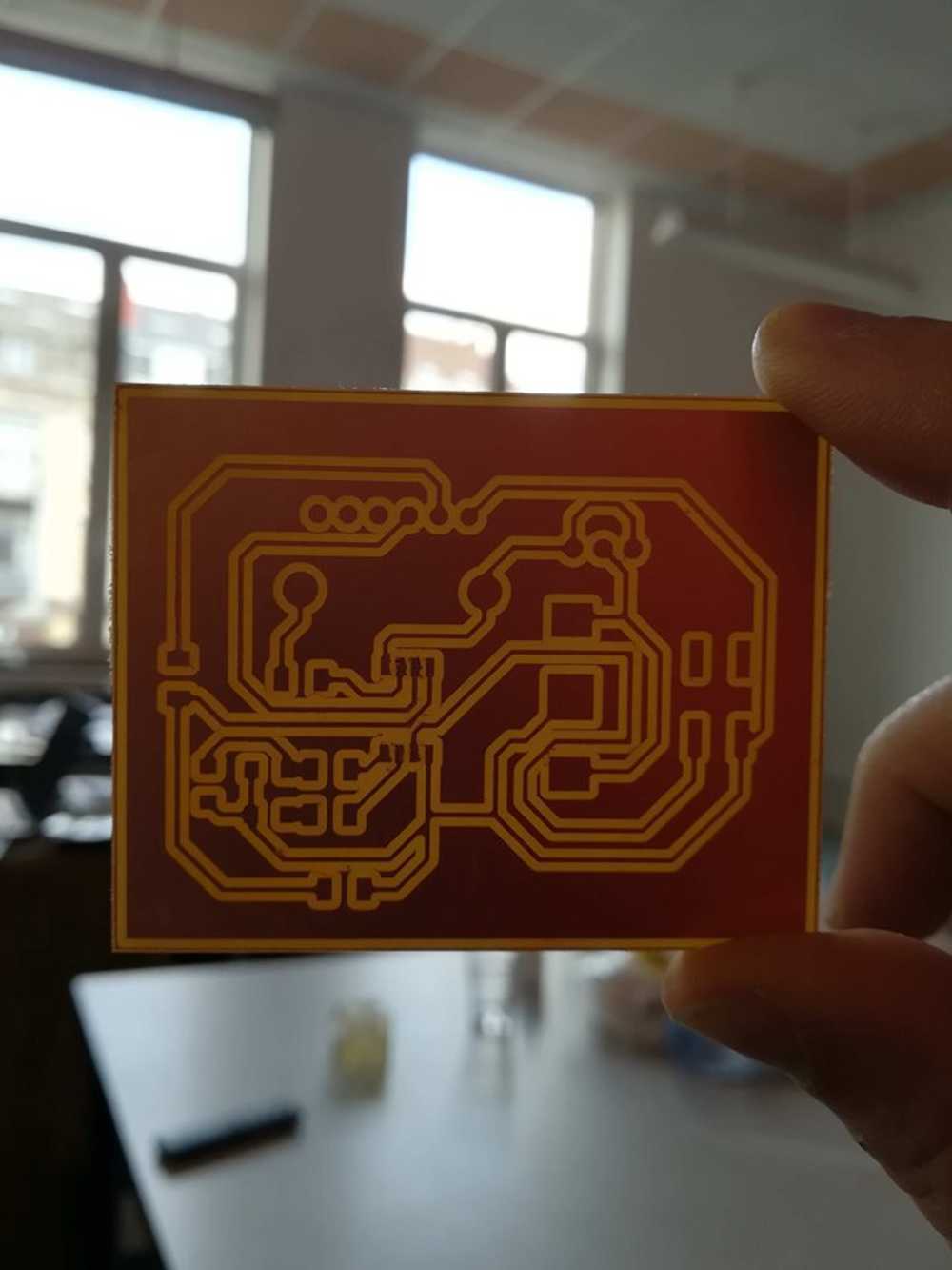 Milled out board
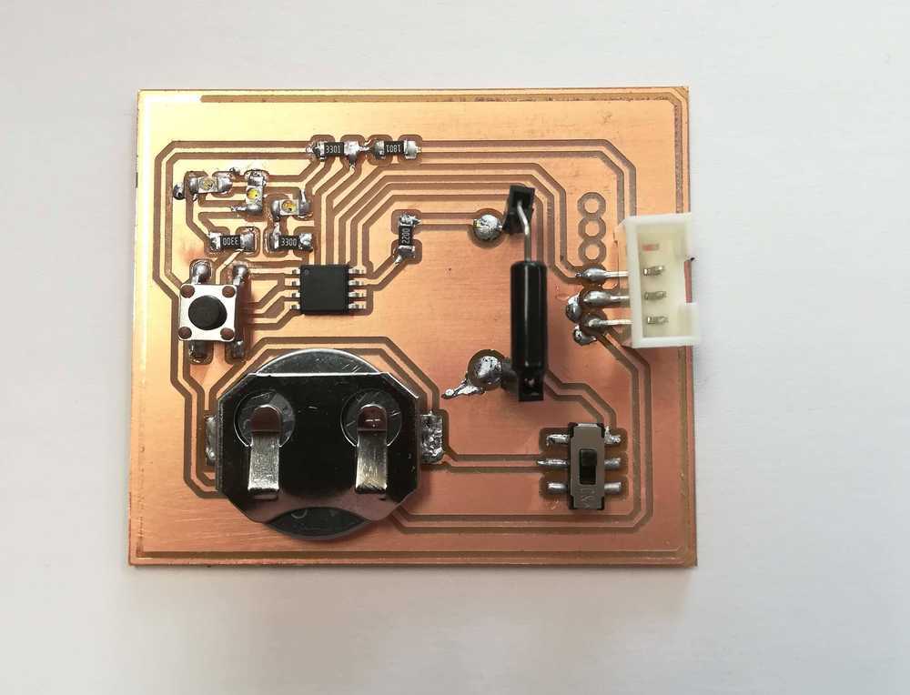 Soldered board
To top
The components
Before you can start soldering the board, you need a list of components. Those can be found below.
- 1x ATtiny85 micro controller
- 1x tilt switch
- 1x slide switch
- 1x push button
- 3x LED
- x 220 resistor
- x 330 resitor
- 1x 1K8 resistor
- 1x 3K3 resistor
To top
Programming the board
The hardest part of this project is to program the micro controller. Once you get the hang of it, it's okay, but the special thing is that you need to overwrite the reset pin of the ATtiny85. Steps can be found below.
- Step 1: Arduino as ISP
- Step 2: load code to ATtiny85
- Step 3: disable reset
My favourite way of programming micro controllers is by using an arduino as ISP. We run it with IDE 1.8, with a 8Mhz internal burn bootloader.
Nothing special about this part. You use the arduino interface to upload the code to the ATtiny85
The next step is more complicated, we need to disable the reset pin by using the next commando
cd ~/.arduino15/packages/arduino/tools/avrdude/6.3.0-arduino9/bin
./avrdude -C/home/USERNAME/.arduino15/packages/ATTinyCore/hardware/avr/1.2.3/avrdude.conf
				-v -pattiny85 -carduino -P/dev/ttyACM0 -b19200 -Uhfuse:w:0b01010111:m
Be sure to change username to the name of your admin and change tot the rigt USB port.
But what happens internally when you do this? The hfuse settings burns the reset disable fuse (first bit will be a 0), but without deleting the program. The 5th bit needs to be a 0 for that. But the SPI needs to be enabled (3th bit a 0)
To top
Hero shot
Soldered board
To top
Next steps
As you feel, I'm not quite done yet with this part of the project. It works, the board is nice and square, but not what we had in mind. To have everything perfec I'd like to develop the PCB into the shape of a fox (or cat), hence the name.
The main part however has been done, the working PBB has been made, code has been written. So the development of the Foxy 2.0 will be for autumn when things at work also calm down. Hopefully, by the start of the next cycle of the FabAcademy, I'll be able to show them how to make non-standard shaped PCB's.
To top
Manuals and files