What you will find on this page:
-
What did I learn during the FabAcademy in 2013?
What do I want to do this week?
The board
Node.js
The code
Starting the application
Oh oh, something went wrong!
Hero shots
Reflection on this week
Manuals and design files
What did I learn during the FabAcademy in 2013?
Back in 2013 I seemed to look forward to this week. I didn't focus on wireless connections but I connected my PCB's through wires. I milled out one bridge board and around 3 nodes. I didn't make specifications on problems while milling out of the boards or the soldering. However, as I still didn't get help with Eagle, I didn't redesign the boards.
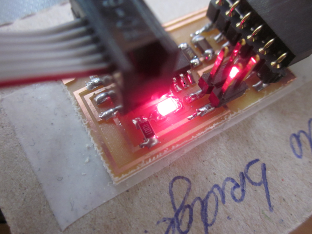
After milling out and soldering the boards came the moment to program them. So I programmed them with the codes from Mercedes. Strange enough it took me a few attempts here to make everything work. We kept trying and in the end tried on another computer. There everything seemed to work perfectly and when we tried again on mine, there were no more problems. I however never specified what my problems in 2013 were when trying to program the board. Or how I solved it.
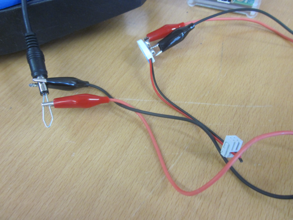
Even after all those years, I still remember the moment when I uploaded my code and made the connections work. I mention 'text' on the blog from 2013, but that should be code. We also did some adjustments on the power supply. At first I connected a 9 volt battery, but he told us to use a 5volt adapter. After some hacking, that still leaves me worried, we managed to get the right amount of power to the board.
The code that I used was:
>>sudo make -f hello.bus.45.make program-usbtiny
>>sudo make -f hello.bus.45.make
When you want to open the python file to let the connection run you use this code:
>>python term.py /dev/tty{your usb gate, same as from the input week} 9600
Looking back on this assignment from 2013 in 2019, my documentation is pretty much worthless and I'm happy I've really evolved on that point.
To top
What do I want to do this week?
For this week I'd like to focus immediately on my final project. In core, networking is not needed in the standard version of the project, but it's nice to show the kids something about it. The PCB that I've been developing during the past weeks will have the shape of an animal, so not just a boring rectangle. This line of visuals I wanted to see further developed within this week. In my head the idea was to have for example a little fox that could open the eyes when there is a plus signal on the board, and they eyes closed when there was a low signal. And maybe, if there is time, have a intermediate picture.

On the part of web development for this and the drawings, I felt confident, but I did wonder how I would get my connection from the board to the computer. I asked a friend for help who guided me through the necessary information.
To top
The board
For the communication between the board and computer I decided to go for a wired USB connection. The first problem that we encountered was that in my original Input/Output design , I didn't have any pins left for extra stuff. As you can see in the weeks of input/output, I worked with an Attiny45. Because of that I looked into using a Attiny44 or Attiny85. But time solved my problem and after sitting together with some people, asking for some guidance and feedback we solved several problems resulting in the use of a Attiny45.
Some of the problems that we were afraid for was that the Attiny can't do serial communication, but we solved that by having the software fix it. At first I was afraid of having to add
an extra component that could handle that.
Another possible problem was the memory. I've tested the communication appart from the programmed LED's, pushbutton and tiltswitch. In the end, after merging the 2 programs, I worked it out
how to reduce code and make it fit on a Attiny.
In general I went through 5 stages with this project:
- breadboarded the buttons, LED and switch (see input and output week) ,
- breadboarded the networking part (without buttons, leds and switch),
- breadboarded everything together with communication through Arduino,
- breadboarded everything together (leds, buttons, switches and communication),
- made the actual PCB.
First test
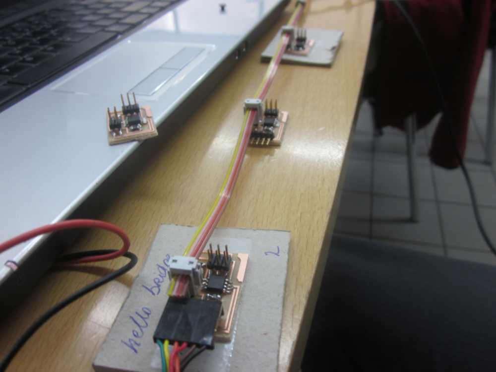
As I couldn't fix the board in time for our meetup, we worked everything out with a breadboard and an arduino. The result looked promising!
We didn't really care yet about the pictures, apart from the fact that they were different from each other, but did have the same extension. Later, once at home I'd draw the actual images that would come on the site.
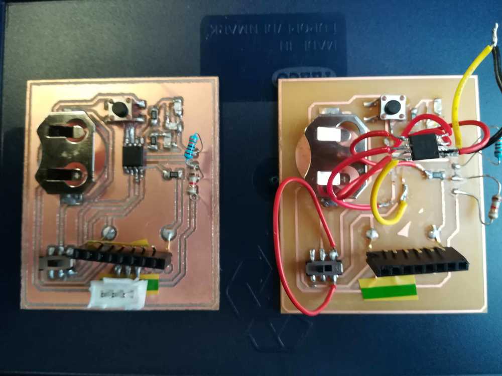
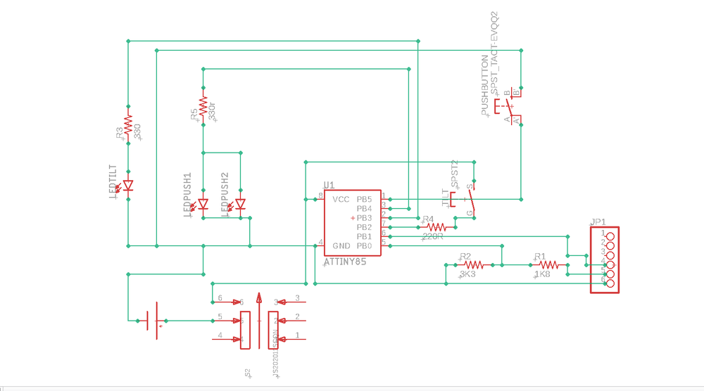
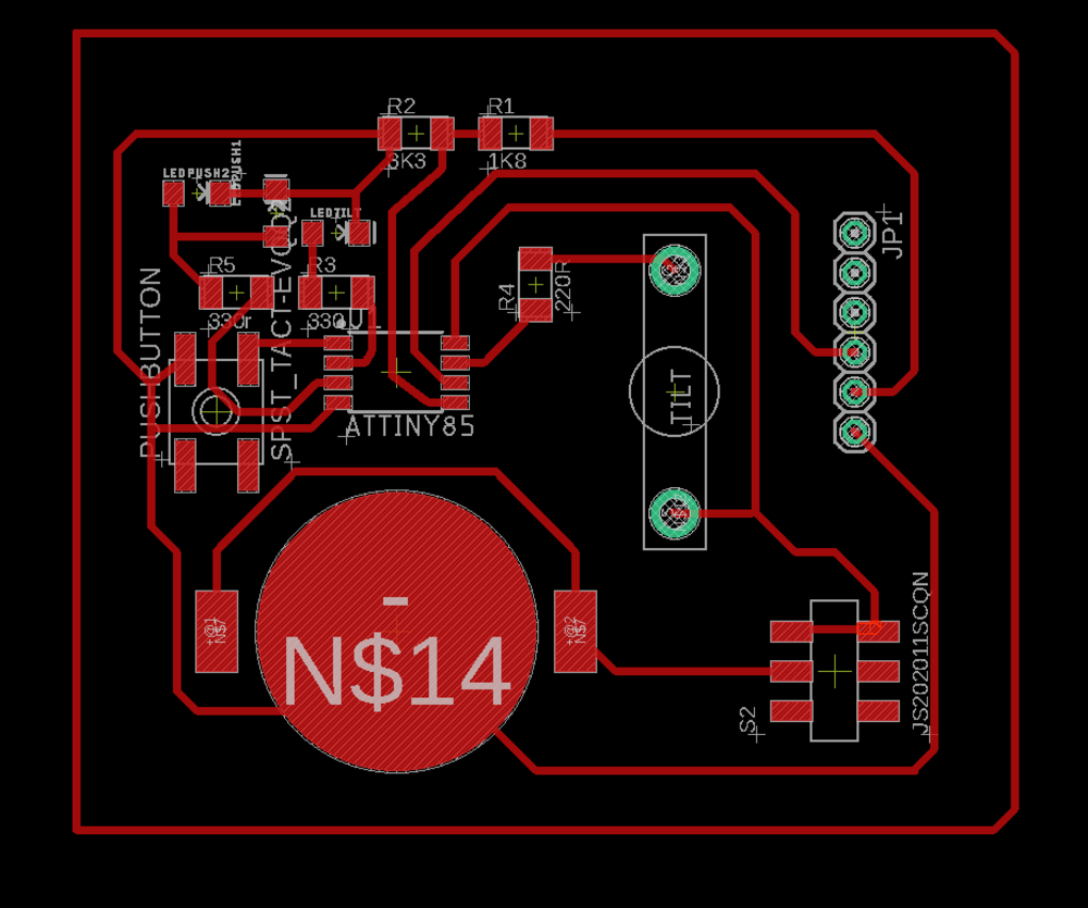
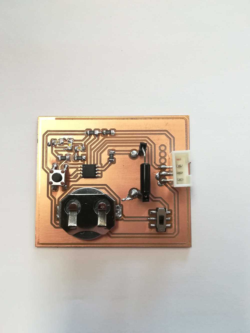
The actual board
I started developing this final board in the input- and output week, but at one point during this week I was afraid that the micro controller that I wanted to use, didn't have enough pins to make everything happen. A second problem was that the memory of the board might not be sufficient enough. In the end I did use a ATtiny85, because of memory issues with the ATtiny44. And I did have enough pins. I decided to overwrite the resetpin. Unless I'm using a bootloader now, there is no way of overwriting the program that I put onto the micro controller. Thanks to the help of an experienced programmer, the loss of ATtiny85's got controlled to about 3 before we got the right program.
As electronics design is not my forte, I needed about 4 boards before I got everything correct. Mistakes ran from connecting the slide switch wrongly to having a broken resistor, to lines detaching. Luckely for me, as I don't have a milling machine in the lab, I carried my etching materials with me. This gave me the opportunity to etch and adapt the PCB wherever I was. One last problem was that I forgot to take the 3K3 and 1K8 resistors from the lab.
After taking out all those mistakes, I finally managed to have a finished board, ready for the evaluation of Networking and the final presentation.
To top
Node.js
We decided to go with node.js but as I had never heard of it, I had a lot of questions about it. I decided to google lot's of stuff about it before our meeting so that I would have a basic understanding of Node.js.
Fore example, what exactly is node.js? another question was what are the pro's and cons about this? and in what do we use it in daily life (without maybe knowing it).
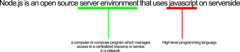
What exactly is node.js was my first question. Simply put: node.js is an open source server environment that uses javascript on serverside. Now, this was a thing that I could understand. I've heard and worked with java script during programming classes and to build this website. A server can be defined as the next: a computer or computer program which manages access to a centralized resource or service in a network. So, the bottom down approach to split up new things that I didn't understand seems to work. Open source, after 8 years in the FabLab world, doesn't need an intro anymore.
What are the pro's and con's about node.js. That friend could tell me 'let's use node.js', but I wanted to know why? Why does he prefer to introduce and teach me node.js over any
other server environment. He happily explained it to me and information on the internet backed his explanation. He explained to me that for what we wanted to do it was the best solution.
It was the easiest way for an all-in one server component that could handle serial connection, host the necessary files (html/js) for streaming to web. If we would have added php to all
of this we would have to install a Apache server while now we just had to install npm and run it.

My last important general question was: where do we use it for? The same as with the ISP that we made, I wanted to have concrete examples of where we use it. And apparently we use it all the time. Whenever you send a delete request to a database (Hence spam databases!), but also chat and games. You can forexample set up Whatsapp with Node.js. But also CMS and blogs make use of node.js. I've worked several times with CMS'es and blogs in the past. So, there is a big chance that the backend on serverside worked on Node.js.
To top
The code
What happens within the code:
The micro controller is programmed to constantly read the port of the tilt switch. There it waits for 0 (no input) or 1 (input) onto the serial bus on my device.
On the laptop a node.js application runs (the node server.js command) that does several things in the background. It gives the images of the cat (in the html) to the client in the browser. Next to that it also opens a socket and keeps track of how many clients there are. In other words, if device A goes to the local host and device B goes to the local host, on the same network, node.js knows there are 2 clients. If device B goes away, node.js knows this, and knows there is only once client left. The last thing it does, is as said before, listening if there is a change in the 0 and 1, and sends it to the clients.
In the html/js script the socket is being opened with the node.js server. And the correct image is being shown depending of the incomming value (0 or 1)
To top
Starting the application.
Of course, making connections and such if fun, but what if you download the files and want to see the changing image? The steps below will help you in that proces.
- Step 1: download the files
- Step 2: Open the terminal in the folder
- Step 3: Check if you have node.js installed
- Step 4: run the node.js
- Step 5: Open the index.html file
As usual, the files can be found at the bottom of the page. Download those and keep them together in a folder.
If you rightclick in the folder you often have an option to open the terminal from there. Otherwise cd ../ to the right folder.
You can do this by using the $ sudo apt install nodejs npm commando and check the version by using $ nodejs --version
You can run the node.js server by using this commando in the terminal: node server.js
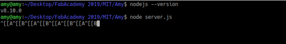
Running the node.js will result in code like the above or in 0 / 1 as you could see in the .gif above.
The whole core of this project is to see in your browser that the eyes of the cat are open of closed. To do this, you need to open the index.htlm page on the next adress in your browser
localhost:8080/index.html
To top
Oh oh, something went wrong!
Of course, every once in a while it won't work. Computers change, folders change and you might run into errors. One of the most common errors that I got was that the USB could not be found. Below you will find the steps to fix this.
Problem: you encounter the device not found error
The sudo chown amy:amy /dev/ttyAMC1 command will let you show the usb device that you use on your computer. Just watch, that amy here is my personal computer, this will
be changed by the admin name of your computer, and the ttyAMC1 is what we named the usb while testing on another computer. As is the case here: the device is no longer called
ttyAMC1. So we get the error: no such file in directory.
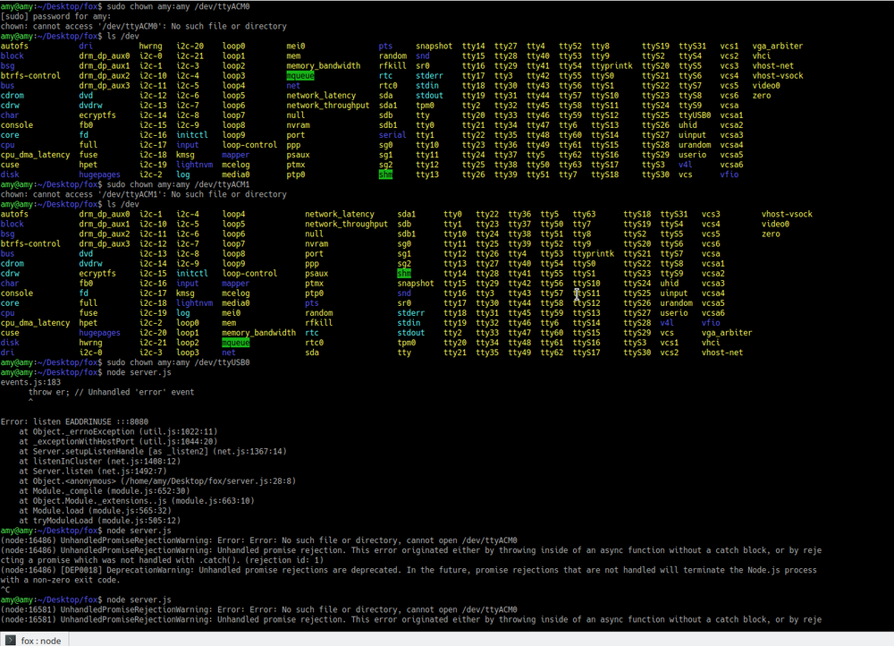
As already shown in the previous picture, you can use the code ls /dev to find the right device. Do this once with the USB connected, do it again without the USB connected.
If you know what you look for, you can do this in one step and just find the right USB. In our case the USB device was called USB0
Knowing the right USB does not solve the full problem, you need to go into the ino code now and change the linked USB device from ttyAMC1 to USB0.
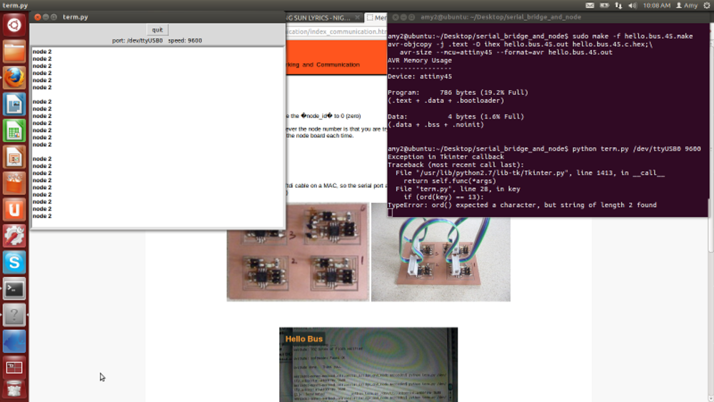
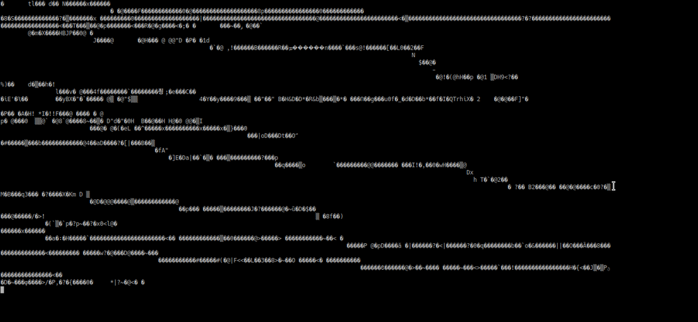
Problem: you kind of set up a connection but you get all weird symbols in the terminal.
Maybe first a quick explanation of what's happening: when you get weird symbols in the terminal (see picture below), it means that here is communication, but not a correct one. Somewhere a line might be twisted, bits and bytes getting lost.
The typical "Have you tried turning it off and on again?". The problem might just lie in a reboot, connection lost (computer in sleep mode...)
As mentioned above, look if the code, PCB and USB are all connected to the same project.
This is a step you might need to do at the beginning of a project when you're still working on breadboards. And that was exactly the problem here. TX and RX were connected, but they were switched. Connection therefore was possible, but not like it should be. See it as when you make UTP cables and you switch 2 colors, data will still pass, but maybe only in one direction. Switching 2 jumper wires, plugging in again and starting the server made the project work perfectly fine.
Problem: communication is to slow
It happens sometimes that when you try to google something and it takes to much time, you have a time-out. The same happens with reading data. Sometimes it's to slow and the devices
time-out. To fix this, there is something called the baud rate. Everyone that once worked within the Arduino environment and programmed a Arduino has encountered this.
Basically, what it does is is a common measure of symbol rate, one of the components that determine the speed of communication over a data channel. (taken from:
Wikipedia)
The baud rate can be found and changed within the code that you made for uploading to the micro controller. In this case we used 9600 baud rate. The 9600 stands for the fact that the serial port is capable of transferring a maximum of 9600 bits/second.
To top
Hero shots!
 Hero shot
Manuals and files