Week 13. Applications and Implications
This week we learnt about applications and implications. We learnt about possible options for the final project and some examples of previous final projects from the alumnus of Fab Academy.
And the assignment of this week is to propose a final project masterpiece that answers a series of questions to tell what it is, what it does, what materials are needed etc.
My Final Project (1) - Whack-A-Word
As I have been asked by many people about how to learn English, I have been thinking about making a project that can help people remember English vocabulary through play games like the game of Whack-A-Mole.

Image Credit: Wikipedia Whack-A-Mole
Now I am thinking about calling it “Whack-A-Word”.
It should have speaker that speaks out the word, and the the respective letters will light up, the player will have to use a mallet to hit the letters by its sequence, and then the word will be shown on a screen.
(sketch to be updated)
Questions to be answered
What will it do?
It should have many functions:
-
It will be able to send out the pronunciation of the word via a speaker, allows the player to whack the letters according to its sequence in the word, and then display the word on a screen. This process is like a spelling bee game.
-
All the keys should have an LED underneath the cap. When the speaker outputs the sound of the word, LED underneath the respective key will light up to indicate the player to whack the right key when it lights up.
-
The keys should be elastic enough and durable to be whacked many times.
-
The keys will be arranged in the some format as regular computer keyboard (QWERTY), in this way I hope it will be helping the player to remember the word by the locations of the letters within a word.
Who’s done what beforehand?
Thanks to the powerful Google search, I found some resources.
I have found that some teachers use Whack-A-Mole vocabulary games to play with kids and guide them to learn alphabet or new words. However, these games are not as interactive as I expect it to be. They usually use cards to play the game. You can get more info from this link.
I have seen some tutorials/instructions about how to DIY a Whack-A-Mole game before. This tutorial How to DIY a Whack-a-Mole Game with Cardboard Box from Hackster.io can provide some reference.
Speaking of the elasticity of the keys, I saw this project during my visit to Korea for the Hello Maker Korea in Busan last October. They used cardboard and rubber bands to make this game at very low cost, and yet they are very robust. I am thinking about adopting their experience into my final project as well.
However, I have not seen anyone made a similar project to what I am expecting to do. I assume my project will be quite complex because I’ll need to have 26 letters connected, send signals between keyboards, a speaker and a display. Hopefully I can make it!
What will you design?
Until now, I haven’t designed anything solid for my final project yet. In previous weeks, I learnt skills related 2D, 3D, laser-cutting, 3D printing, molding and casting etc. However, when I was doing my weekly assignment, I did not actually deign or make any parts for my final project yet.
What materials and components will be used?
Where will come from?
How much will they cost?
To answer the above 3 questions, I will create a chart to show my planning for materials, parts, the source for materials as well as estimated cost.
| Item | Component/Material | Quantity | Source (where) | Cost per unit | Sub-total (RMB) | Note |
|---|---|---|---|---|---|---|
| 1 | wood or OSB | 7 | local vendor | ? | exclosure + stand for display | |
| 2 | keycap | 2 | 3D print | - | - | |
| 3 | LED | 26 | ? | ? | ||
| 4 | LCD Display | 1 | Seeed | ? | ? | |
| 5 | rubber band/ spring | 26 | Taobao | ? | ? | |
| 6 | micro controller | |||||
| 7 | communication module | |||||
| 8 | cable |
What parts and systems will be used?
Currently I am thinking about using Arduino as the controller. I might design a simple Arduino by myself. Still need to figure out the details.
What processes will be used?
- 2D design: to design the structural parts of the project, I will design with Inkscape and then export it as dxf. files.
- CAM: Turn the dxf. files into tool paths and then us CNC to make the structural parts.
- 3D design : use FreeCAD to design the keycap.
- 3D printing : use 3D printer to turn the 3D design keycap into actual parts.
- Laser cutting/engraving : to cut the hole for putting the LCD display and also engrave some pattern/words on the project.
- Vinyl cutter : to make stickers to make the surface look beautiful.
- PCB design : will use Eagle to design my own boards.
- PCB milling : Will use CNC to mill the PCB boards I designed.
- soldering : solder parts onto the PCB board.
What questions need to be answered?
-
How does it communicate between the speaker, the LCD display and the keyboard?
-
How much is the power supply? How to provide power?
-
How does the user update the vocabulary library based on what they want to learn/review?
How will it be evaluated?
- the communication between different parts, make sure it’s smooth and robust.
- the durability of the keys. How many whacks can it hold?
- the power supply. How much power does is need? Will it be possible to use a portable power supply so that I can be used outdoor? How long can it last if with a 10000mAh power bank?
My Final Project (2) - Camera Trap
After talking with my colleagues and friends, as well as further thinking about the “Whack-A-Word”, I am thinking it might not be the right project that I should make. First of all, there has been a lot of apps available for people to practice and memorize English vocabularies. With the APPs on the phone, people can learn on-the-go. In this way, people can learn during some trivial intervals between work and rests, among commutes etc. Comparing to the already advanced and evolved APPs, the “Whack-A-World” game machine doesn’t seem to be bringing any new functions.
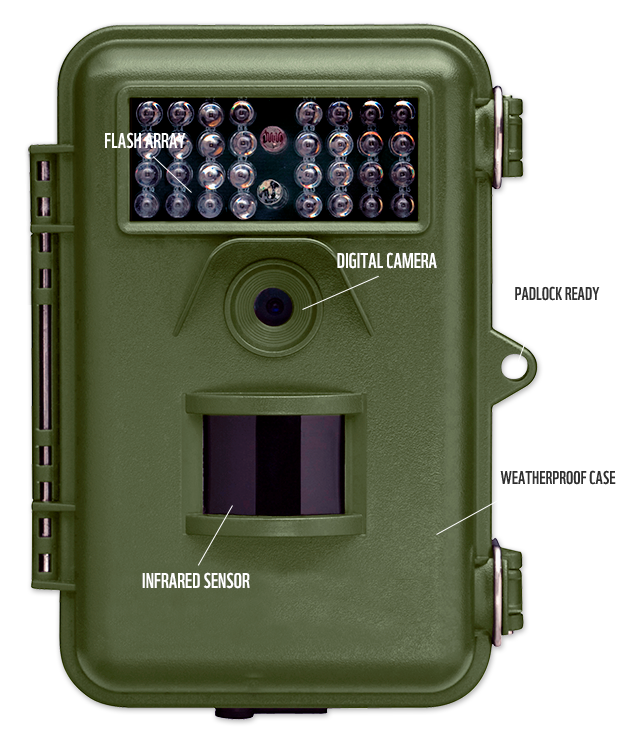
(Camera Trap, Photo Credit: WWF)
So I have been thinking what are other possible projects that I can make. It occurred to me that a camera trap might be something worth trying. There is a story behind this project. I have recently made a new friend also a Seeed Ranger, Arky who has been living in Cambodia, working on conservation works such as the Cambodian Fishing Cat project that studies the highly endangered fishing cat and hairy nosed otter. And Arky mentioned that the current camera traps were actually designed for hunters and it would be great if we have a camera trap that is specially designed for conservationists, biologists and scientists who have been working on conservation works.
With a few materials shared by Arky, I began to learn more about camera traps.
- Camera trapping for conservation
- Conservation technology
- CameraTraps WWF guidelines
- Camera traps for researchers
Thanks to these materials, I came up with a few questions to discuss with Arky to get a clearer picture of the camera trap. Questions raised by Violet and answers provided by Arky! Thank you Arky for providing the answers from your experiences and real practice needs.
-
Q1: Should it be a camera trap for taking pictures or videos? Or both? If both, what is the priority?
A1: The commercial camera traps are setup by the researchers to either take photos or short videos. Usually photos are most popular as it helps identify the animal and doesn’t take much space on the SDCard. -
Q2: What is the expected price range for this product?
Q2: It depends on the features. An average good quality the camera traps start from $250 - $450 USD depending on the features. -
Q3: What is the environment that you’d like to use the camera trap?
Q3: Usually the camera are used in insect filled, dusty and high humidity/wet conditions. So the case needs to be weatherproof IP67/waterproof if possible. -
Q4: What should be the trigger for the camera to start taking photos/videos? Should it be infrared or PIR motion sensor or other or sth. combined?
A4: The commercial camera traps are triggered by PIR motion sensor. These motion sensors are high quality and camera starts recording within few seconds. -
Q5: Do you expect it to be infrared or incandescent?
A5: The low-end models use IR cameras, the medium range models use some form of red/white flash. The most expensive models use a newer starlight camera. -
Q6: What is the expected way of accessing the pictures/videos? Offline by connecting the SD card with laptop etc. or online by connecting to the cloud and access realtime?
A6: The photos are collected by taking the SD card out and copying out the images. -
Q7: Should it be a complete product that has built-in sensors on the board? Or should it be a kit that conservationists/biologists can assemble directly? If it’s a kit, what parts are needed for it to be fully assembled?
A7: Camera traps could be a complete product that ready to use by adding batteries, SDcard and configured using a LCD with couple of buttons. This has most widest market.
The ability to customize, repair and add sensors to collect environmental data would be a killer feature.
A more DIY conservation kit caters to smaller segment of the market who are interested such kits for educational, experimental research for custom data collection conservation.
At the moment Grove kit have all the required components expect a good IR camera module. I am still doing research about this. -
Q8: What is the expected power supply for this product? How long is it expected to last?
The commercial camera traps last for a whole year on a dozen AA batteries. The commercial camera trap boards have deep sleep mode and rarely consume much power. AA batteries are preferred as they can be bought locally anywhere in the world.
However, lately scientist are looking for more renewable energy alternatives like the Li-ion/Li-po batteries with solar charge controllers. But it is not always possible to put solar panels and forest animals/insects tend to chew any exposed power cables. -
Q9: What is the expected dimension of the product?
A9: The smaller the better!
Usually it is the weatherproof case that takes most of space apart from the battery compartment. The camera traps often have a metal cage and metal wire to prevent them from being stolen or destroyed by poachers, sun bears and elephants :)
And then I had another Skype call with Arky to further discuss about ideas for the camera trap, it seems there has been a lot of problems lying ahead. Hopefully they can all be conquered!
Questions to be answered
What will it do?
It’s a camera trap kit that can detect wild animals and then take pictures of the animals, which will allow scientists, biologists, conservationists to study the endangered species in the wild.
Who’s done what beforehand?
There has been some camera traps made by other makers previously. Here are but a few examples.
1. This is a video tutorial from Wired: How to Make a Camera Trap
2. This is a tutorial by stinkyabb from Instructable: Simple PIR DSLR Camera Trap
3. This is another tutorial by stinkyabb from Instrutables: Building an Active Infrared DSLR Camera Trap for Wildlife Photography
4. This is a tutorial by Scott Eggnimann from Wildlifecameratrap.com DIY Simple PIR DSLR Camera Trap
5. My friend, hacker in the wild Andrew Quitmeyer made this 360 Virtual Reality Camera Trap and shared it on instructables as well.
What will you design?
I will design a camera trap kit which will allow conservationists to assemble the parts and then it will be ready to take photos when it detects animals within the range.
What materials and components will be used?
Where will come from?
How much will they cost?
| Item | Component/Material | Quantity | Source (where) | Cost per unit | Sub-total | Note |
|---|---|---|---|---|---|---|
| 1 | MCU - BeagleBone Green | 1 | Seeed Studio | 44USD | 44USD | |
| 2 | PIR motion sensor | 1 | Seeed Studio | - | - | |
| 3 | Camera | 1 | Taobao | 200RMB | 200RMB | |
| 4 | Grove PIR Motion Sensor | 1 | Seeed Studio | 7.9USD | 7.9USD | |
| 5 | Grove High Precision RTC | 1 | Seeed Studio | 8.59USD | 8.59USD | |
| 6 | Grove LCD Display | 1 | Seeed Studio | 11.9USD | 11.9USD | |
| 7 | Audio Microphone | 1 | - | 10USD | 10USD | |
| 8 | Grove Cape | 1 | Seeed Studio | 5USD | 5USD | |
| 9 | buttons | several | - | ? | ? | |
| 10 | Grove cables | several | - | ? | ? | |
| 11 | battery pack | several | ||||
| 12 | water-proof case | 1 | ||||
| 13 | SD card | 1 |
What parts and systems will be used?
After discussing with Arky, we decided to use BeagleBone Green as the system. In this case, the communication between the PIR sensor and the trigger of camera is crucial. So I might user other systems if it can process faster.
What processes will be used?
- 2D design: use Inkscape to design the case of the camera trap.
- molding & casting: Since the camera trap requires water-proof, I might use molding casting to make a water-proof case for it.
- 3D design : use FreeCAD to design the case of the camera trap.
- 3D printing : use 3D printer to turn printe out the 3D printed case.
- Laser cutting/engraving : use laser-cutter to cut the case and engrave some patterns/words on the surface.
- Vinyl cutter : to make stickers to make the surface look beautiful.
- PCB design : will use Eagle to design some boards (still not sure which parts will need to be designed by myself yet. I will need to use the existing products to make a proof of concept before getting started on making my own design).
- PCB milling : Will use CNC to mill the PCB boards I designed.
- soldering : solder parts onto the PCB board.
What questions need to be answered?
- How long will the battery last?
- How many photos can the camera trap take with the power supply & SD card?
- How large is the camera trap?
- How to protect it from the animal’s activities in the wild?
- How long will it take for it to take a photo after the PIR sensor detects something?
How will it be evaluated?
- The completion of the project
- The time interval between PIR sensor detection and the picture taken (the shorter the better)
- The quality of the pictures taken
- The water-proof function of the project
My Final Project (3) - Auto-irrigating/extending Shelf/System for Green Plants
I have been thinking about the Camera Trap project and discussing with Arky about the requirements, the expected functions etc. I’ve also asked my colleague Pillar at Seeed to learn about possible solutions. It seems Raspberry Pi with this camera will be a better solution. I am still very interested in this project, however by doing this project it doesn’t seem I can do much customization (except the case part) for it. And I am worried it might not meet the evaluation criteria for the final project.
As a result, I am considering another project. This is a project with a long name (which is not a confirmed name yet). However, it seems to be the project that I will have a higher possibility to complete within the timeframe of Fab Academy 2019.
In Week 8 - Computer Controlled Machining, I made an extendable shelf, whose 2nd & 3rd layers will be able to be pulled to pulled to two opposite sides so that the green plants on these two layers will be exposed to sunlight. It requires manual operation to pull out the layers as well as manually irrigate. And I am thinking about turning into an automatic system as my final project.
You can see from the above video how the two layers of the shelf are pulled to the opposites.
And this is the current condition of the shelf - we began to plant some flowers when we collect the recycled bottles!

(Extendable Shelf - photo taken on April 21st, 2019)
Questions to be answered
What will it do?
It is a green plan automatic project that can pull the 2nd and 3rd layers of the shelf to two opposite sides when the sunlight comes out. And it should be able to automatically irrigate the green plans when the soil humidity is below the pre-set level.
Who’s done what beforehand?
What will you design?
For mechanical/structural parts:
- I will design an extendable shelf. (This is completed in week 08 assignment).
For electronic parts:
I will design the followings:
- a motor-controlled system to move the shelf
- a soil-humidity sensor that can detect soil humidity of the green plants (input device)
- a sunlight sensor that can detect sunlight and trigger the motor to move & pull out the shelves (input device)
- a microcontroller similar to Arduino to control the system
What materials and components will be used?
Where will come from?
How much will they cost?
| Item | Component/Material | Quantity | Source (where) | Cost per unit | Sub-total (RMB) | Note |
|---|---|---|---|---|---|---|
| 1 | wood or OSB | 1 | available at Chaihuo x.factory | - | for making the extendable shelf | |
| 2 | water pump | 1 | local vendor | - | - | for irrigating the green plants |
| 3 | MCU - Arduino | 1 | make one | ? | ? | |
| 4 | rubber tube | 1 | local vendor | ? | ? | for transporting water |
| 5 | motor | 4 | Taobao | ? | ? | |
| 6 | motor driver | 4 | ||||
| 7 | soil humidity sensor | 1 | make one | |||
| 8 | sunlight sensor | 1 | make one | |||
| 9 | power supply | 1 |
What parts and systems will be used?
I will use Arduino to control, and I am thinking about designing an Arduino-compatible board by myself. And I will also need sunlight sensor(UV sensor)
What processes will be used?
- 2D design: Use Inkscape to design the shelf and export it as dxf. files for CAM.
- CAM: Use MasterCAM to create paths and then export for cutting on the CNC router.
- PCB design : design the PCB boards needed for this projects, including a micro-controller and a soil humidity sensor.
- PCB milling : use Roland - SRM20 to mill the PCB boards.
- soldering : Solder the components onto the board
What questions need to be answered?
- How to communicate between the motor driver and the sunlight sensor?
- How to make sure the shelf is moved to a certain range (so that it will not fall off)?
How will it be evaluated?
- The shelf should be a press-fit construction project and be stable for hosting many bottles of green plants.
- The system should be sensible enough when it detects sunlight it should trigger the motor to pull out the shelves. And it should pull the shelf back when there is no sunlight detected.
- The motor should be powerful enough to be able to pull out the shelves with plants on it.
- When the shelf is pulling out, it should be stable enough and won’t affect the green plants’ conditions. (won’t cause the plants to fall off the shelf).