
Fab Academy 2019 - Lucas Lim
08. Computer-Controlled Machining
08. Computer-Controlled Machining
Group assignment:
Individual assignment:
The goal of this week assignment is to make something big! in which we have to design and fabricate a press-fit furniture/product of considerable size like a bookshelve, table, chair, etc.
This week is actually a 'continual expansion' of the digital fabrication skill from previous weeks. Leaning how to handle large stock material (like 4ft x 8ft plywood), a larger machinery, a larger cutting tool and etc.
The main challenges for me this week was that the large format CNC machine in both our SP Fab Lab as well as the large format CNC machine in another school were out-of-order and I am not able to mill my furniture till a later date when the new replacement CNC machine arrives.
Before I start my design, the first step is to have a look at
Conventional way of makeing furniture would typical include the use of circular saw/radial saw, various hand tools like chisel, cordless drill, etc. to manually cut out the plywood into pieces and the shapes that you want, then secure by using fasteners like nails/screws or wood glue. The design might be simply sketches out using a piece of paper. This method is like 'manual' machining which is often what I did in my carpentry workshop.
With computer getting less expensive and more powerful, we are now able to use computer to control cutting.
In digital fabrication, we are using a computer to sketch out our design then send to a CNC machine for milling. Whole process is digital which refer to as CAD (Computer-aider design) and CAM (Computer-aided manufacturing).
"CNC" stands for "Computer Numerical Control" and the abbreviation name "CNC" is a prefix attached to any machine that is able to be programmed (by a computer) to perform computer-controlled cutting to carve out the shape of the part you want.
CNC machining allow us to easily cut out our design with greater accuracy, increase productivity, reduce manpower, among other benefits. The computer-generated tool path make it easier for us now to make much complex parts.
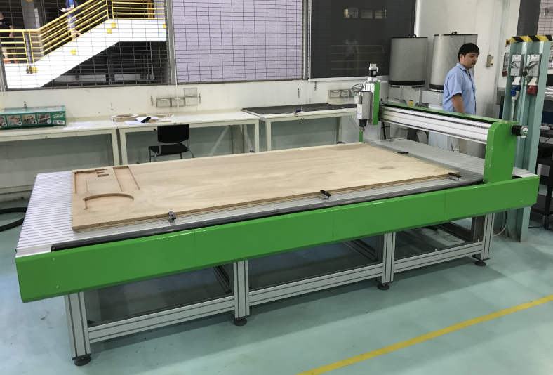
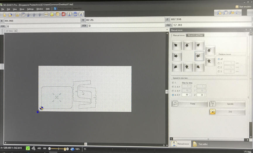
For this week assignment, the large-format CNC milling machine I am using is a 'VERSATIL 2500' with a working area of 2.5m x 1.25m x 17cm in the Fab Lab. This was newly purchased by the Fab LAb and I was one of the first few users of the machine.
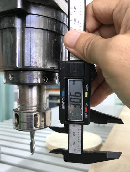
Here I am using a 6mm diameter, two-flute, with center cutting, up-cut, flat end mil is used.
|
CNC router need a cutting tool or 'bits' to cut. Bit comes in many types.
End mill are design to cut from the side, as compare to drill bit which use to drill hole. A end mill is also much shorter than a typical drill bit. Up-cut end mill comes with cutting edge that pulls the cut material (or chip) upward as it cuts is known as an "up-cut" bit. This is the most common. The upcut end mills leave a poor edge quality on the top of the workpiece. Down-cut end mill comes with cutting edge that push the cut material (or chip) downward as it cuts is known as "down-cut" bit. The upcut end mills leave a poor edge quality on the bottom of the work piece. Compression end mill comes with a combination of both up-cut as well as down-cut flute that provide the best quality in top and bottom edges of the workpiece being cut. Stright end mill is best for general-use cutting with a good edge quality on many materials. Center-cutting (tip) end mill can plunge into the material (like a drill bit) and cut horizontally. Ballnose bit has a round tip and is good for carving large 3D contours or carvings. Engraving bit (or sometimes called v-carving bits, or v-bit) has a v-shaped tip and is good for lettering and signs. Size of end mill : A larger size end mill or bit will remove a lot of material fast, but a smaller bit will cut and produce much finer detail along the edges. |
Reference :
Make : 6 Essential End Mills for Your CNC Machine
The workpiece that is going to be milled is known as the "stock".
My stock is a 4ft x 8ft (1219mm x 2438mm) plywood. The thickness of the plywood is 11.6mm.
| Item | Description |
|---|---|
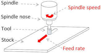
| Spindle | The spindle spin the cutting tool/bit. |
| Spindle Speed | how fast the spindle turn (or how fast the end mil will turn). Usually measure in rpm |
| Feedrate | the speed of travel of the spindle, measure in m/min |
| Chipload | the amount of material that is shaved off by the end mill per cutting edge. A correct "chip load" is important as it prolong the tool life, usually provide a cleaner, smooth and fast cut. |
| Depth per Pass | Depth per pass is how much to cut per pass. Number of pass will depend on the size of the end mill. |
| Flute | the void in the end mill. these void is like "thread" that wrap around the end mill. It pushed the cut material (called chip which is shaved from the cutting edge) either upward/downward depening on the end mill used |
| Number of flutes | the number of flute/thread that wrap around the end mill |
| Kerf | In cnc cutting, material is being unintentionally removed by the cnc cutting process due to the tool width of the end mill. Kerf therefore refer to the allowance for the tool width (typically the diameter of the end mill used). |
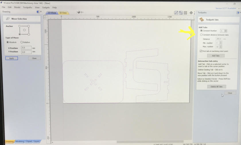
| Tabs | "tabs" which are tiny bridges created to hold the milled part to the "stock" material. Sometimes, you can use screws to secure the milled part to the "sacrifice board" |
| Cut depth | The distance (or amount) that the end mill will cut into the material with each pass. |
| Step-over | The distance (or amount) that the end mill will move over after each cut. |
| Sacrificial board | "Sacrificial board" (also sometimes call "spoil board" or "waste board") is where you place your material to be cut. The Sacrificial board protects the bed of the machine from being cut into as well as secure/hold the "stock" material. |
To have a good cut, it important to select the best cutting speed (feed rate) and spindle speed(speed of rotation)
If you machining too fast, or too high a feed rate, it causes excessive cutting tool wear, it shorten the lifespan of the end mill or even break the end mill. If you machining too slow, you wasting time, it also creates a lot of "rubbing" on the surface, insted of cutting. Slow feed rate will "dull" the cutting edge and generate excessive heat. Look for a sweet spot and you will hear a sweet machinery sound.

Image from https://www.cnccookbook.com/feeds-speeds-wood
The green areas reflect ideal Sweet Spot matches for a material and cutting conditions. You can optimize MRR (Material Removal Rate), Surface Finish, and to an extent a blend of all three. Red reflects danger zones.
~ https://www.cnccookbook.com/feeds-speeds-wood/
"Chipload" is the amount of material removed with each pass. As the end mill flute's cutting tooth bites into the wood, a small chunk of wood is removed, chipload is the thinkness of that chuck.
Some end mill manufacturers (like Onsrud) might provide the optimal chipload for the tool they produce.
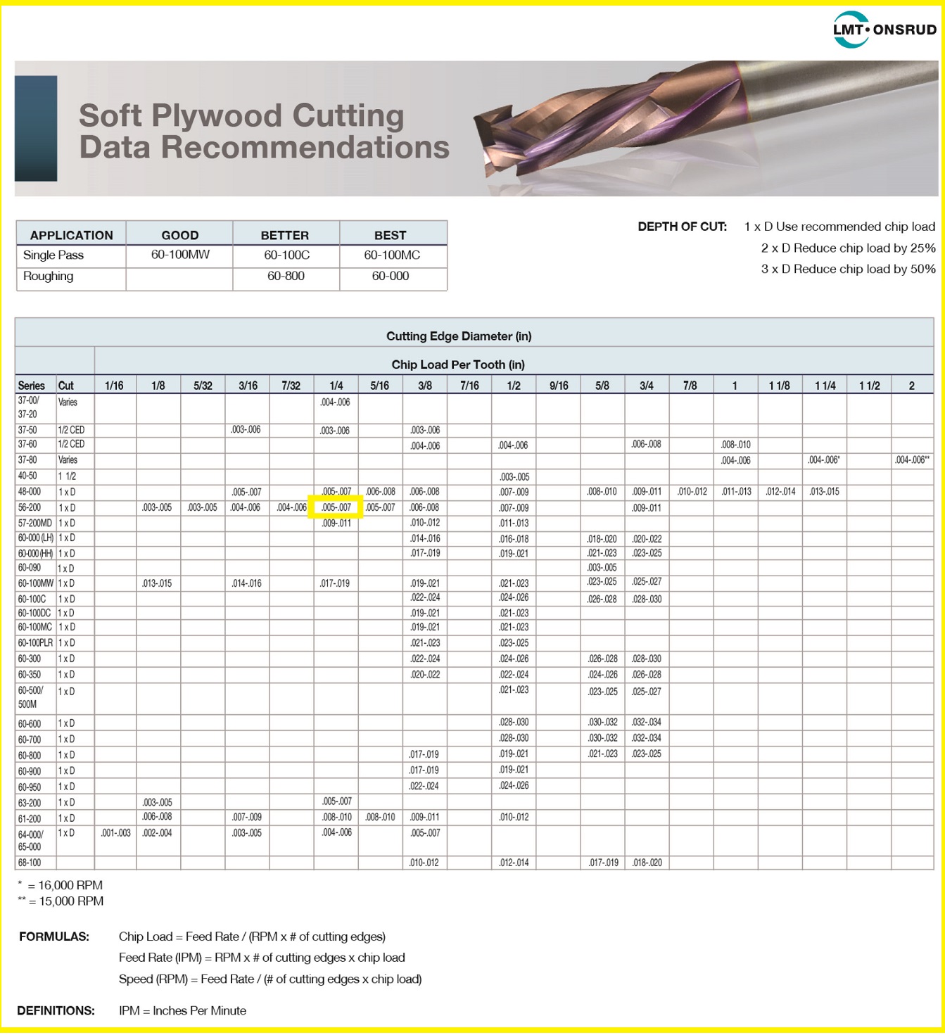
Refering to the chart provided by Onsurb's recommendaion and calculation to save time. The chart is for soft plywood cutting, and the Onsurb end mill series number is provided. This is used as a refernece or a good starting point for the calculation of feedrate and spindle speed.
Chipload indicated for solid carbide, straight, 1/4 inch (6mm) end mill is 0.005 ~ 0.007 inch (0.127 mm to 0.1778mm),
for a cut depth of 1 x D (diameter) of tool at a rpm of 18,000.
The chip load is within the chip load range recommended on Fab Academy class site too : ~ 0.001-0.010" which is very safe figure.

The chip load is between 0.005 ~ 0.007 inch. Here we take 0.006 (the average of the high and low) as reference. Taking the average will allow me to have some tolerance up and down to play with.
Spindle Speed : 18000
Feedrate = RPM x Number of Flute x chipload = 18000 x 2 x 0.006 = 216 IPM (or 5486.4 mm per minute)
(PS: we do not wish to push the bit too far, to beyond 200 IPM, as feeding too fast might break the tool ~ source: CNC Routing Basic:Toolpaths and Feeds 'n Speeds)
Reducing Spindle speed to 15000.
Feedrate : 15000 x 2 x 0.006 = 180 IPM (or 4572 mm per minute)
cut depth : ~ tool diameter = 6mm
step-over : ~ tool diameter/2 = 6/2 = 3mm
The above calculation is for guidance only :
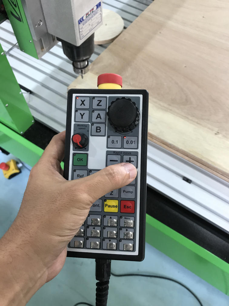
Actual Feed Rate used : 25mm/sec or 59 IPM (as recommnded by Fab Lab technician)
Actual Spindle Speed used : 12,000 (manually set on machine)

Reference :
- LMT-Onsrud latest Cutting Data Recommendations
- Definitive Guide to Feeds and Speeds for Wood [2018 update]
- CNC Routing Basics: Toolpaths and Feeds ‘n Speeds
- Edward Ford, 2016, Make : Getting started with CNC, Maker Media, Inc. CA, USA.
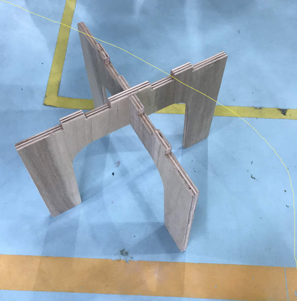
Wood can be held together using joints, some are simple and some are complex. I am using the following joinery in my design.
Mortise and tenon joint
|
Essentially a peg in a hole, where the mortise is the hole and the tenon is the peg. Simple and yet very stong. |
Cross Lap joint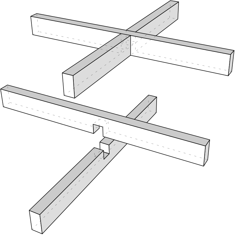
|
A joint in which the two members are joined by removing material from each at the point of intersection so that they overlap. |
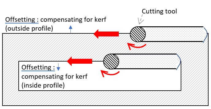
The toolpath define the the route that the cutting tool (end mill) will follow to machine a part. However, the cutting tool used is circular and therefore has a certain diameter, resulting in the removal of valuable material (that we need) along the toolpath.
Kerf is the width of the material removed by the CNC cutting process. The kerf is set as tool width of 6mm.

Image from - ESAB Knowledge center : What is cutting kerf
Kerf = Tool diameter = 6mm
Thickness of stock = 11.6mm
Compensationg for kerf :
To compensate for the kerf, the end mill need to be offset from the vector (line) by half the diameter of the cutting tool. Outside profile (external boundary) need to increase by 3mm, inside profile (cut feature inside the part) need to decrease by 3mm.
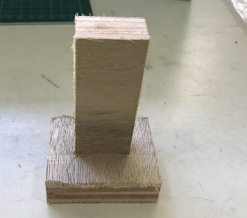
I am using a 1/4" (6mm) end mill. I drew some rectangular holes of size to test my joints.
Run a test job to test the machinery cutting :
By doing a test cut not only can be determine the kref, but we can also observe the machining process on the following :
- observe for any runout, or alignment issue.
- observe a vertical cut is really vertical.
- observe the cut of a square will come up as a square.
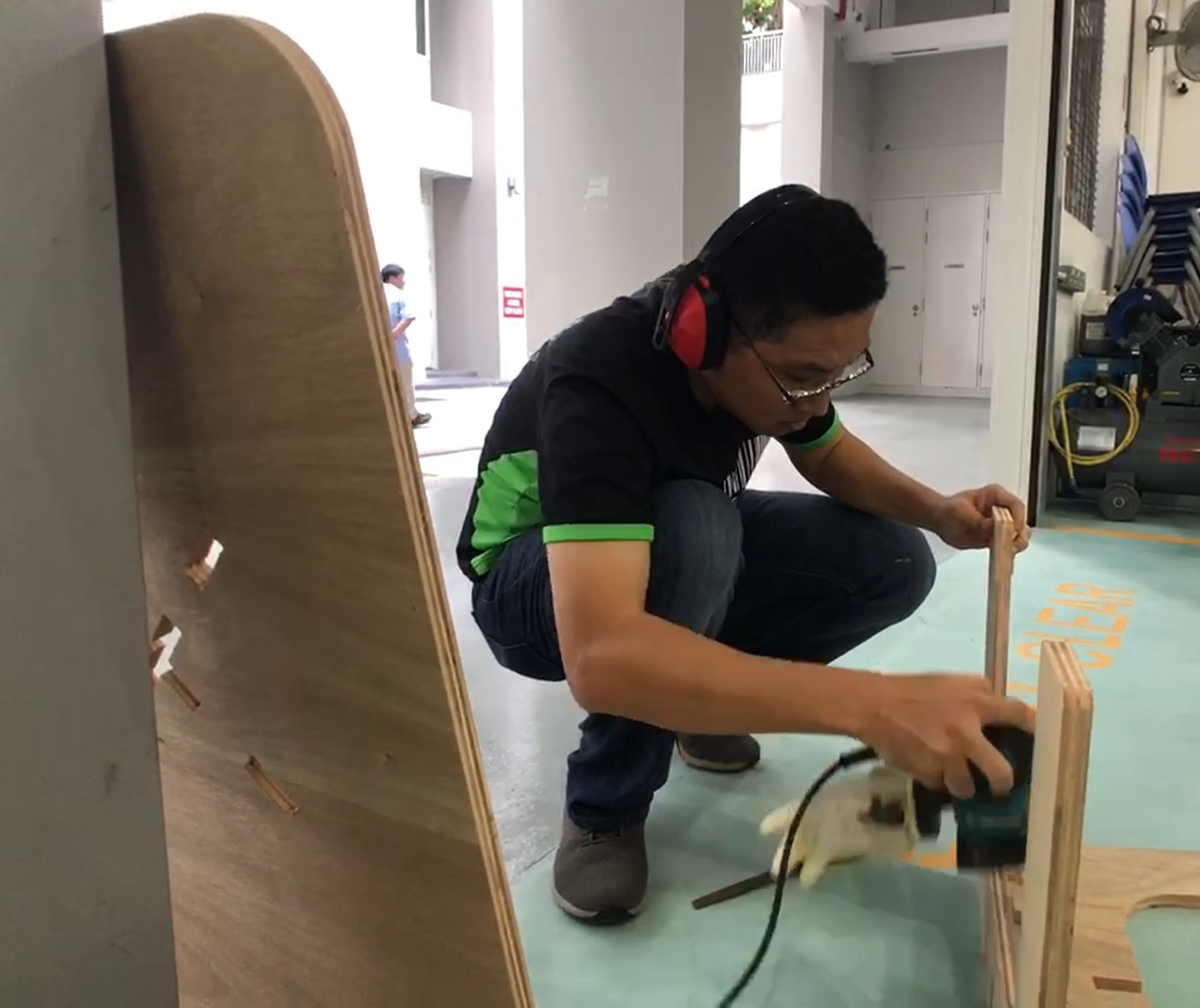
Actual testing (Group Assignment) :
The new milling machine was able to easily auto-adjust for 'kerf' by selecting the direction of the cut for cutting inner profile (hole, pocket) or outer profile (boundary of shape).
The length came out very accurately, it was exactly 100mm. The hole and the 'pocket' also were accurate. The 45mm dia. circle was a bit off, -/+ 1% off probably the 1mm length 'tabs' was too small to hold the piece together.
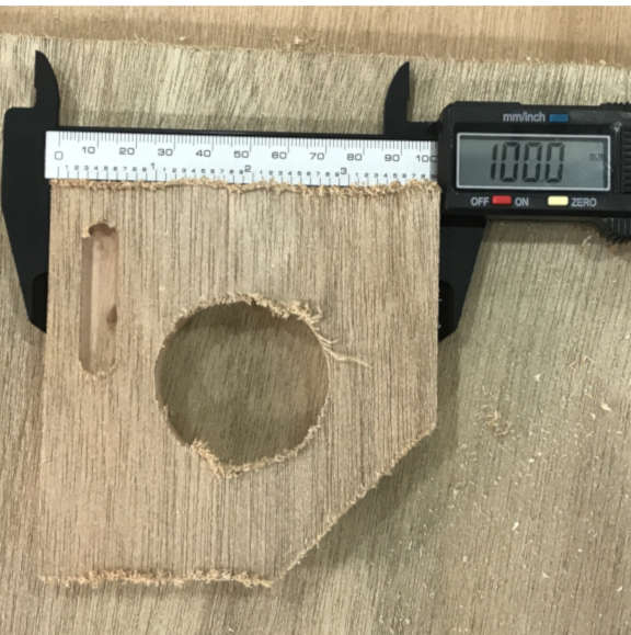

I adjsuted my testkit file to just cut out the actual dimension, without compensation for 'kerf'. It was very tight to fit the 'stick' into the 'slot'.
File :
- testkit for kerf (cnc router)
Reference :
- ESAB Knowledge center : What is cutting kerf
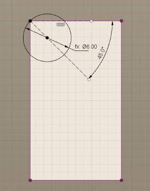
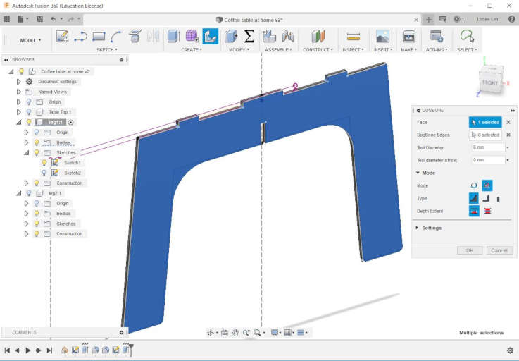
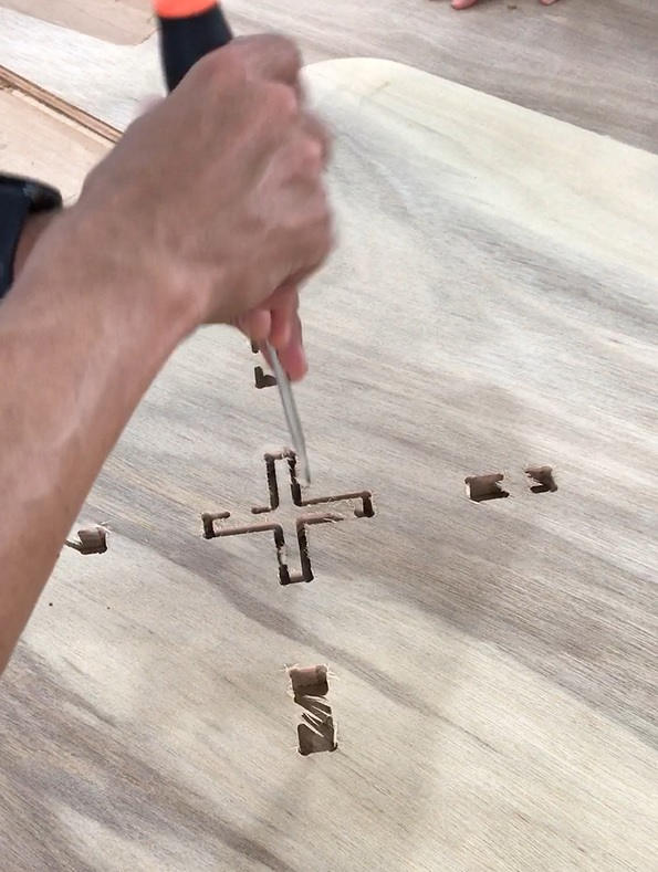
During the cutting of internal corners, especially a 90 degree angle as shown below, there will be portion that are left uncut with a round cutting tool. These uncut portion will affect my part from slotting-in prefectly. Therefore it is important to have "dogbone" fillet for the round cutting tool to cut in-and-out to remove these uncut portion.
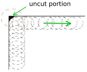
To remove the uncut portion and enable a correct fit, a "dogbone" fillet is applied to the internal corner(s).
Steps to install a "Dogbone" creation add-in for Fusion 360 :
1. Downlaod the zip file from Casey Rogers' GitHub website at https://github.com/caseycrogers/Dogbone

2. Follow the installation instruction as provided on the GitHub website
Extracted and placed the files in the "Add-In" folder at %appdata%\Autodesk\Autodesk Fusion 360\API\AddIns
(For me it is located at C:\Users\Lucas\AppData\Roaming\Autodesk\Autodesk Fusion 360\API\AddIns\)
3. Launch Fusion 360 -> On the main menu toolbar click on "Add-ins" icon -> select
"Scripts and Add-Ins" -> Select "Add-Ins" -> Select "dogbone" add-in that you just downloaded.
(If you are not able to see the add-in, click the "+" sign beside the title "My Add-Ins" to manual select the folder location of the Add-In)
4. Tick the "Run on Startup" (to have the dogbone add-in automatically loaded each time you open Fusion 360) and Click the "Run" button.
5. The new add-in "dogbone" icon will appear in the "Create" category on the main toolbar

References :
Autodesk Community on Fusion 360 regarding dogdone add-on
Downlaod of dogdone add-on from GitHub
Youtube video tutorial on installing and using Dog Bone Fillets in Fusion 360 (For CNC Routers)
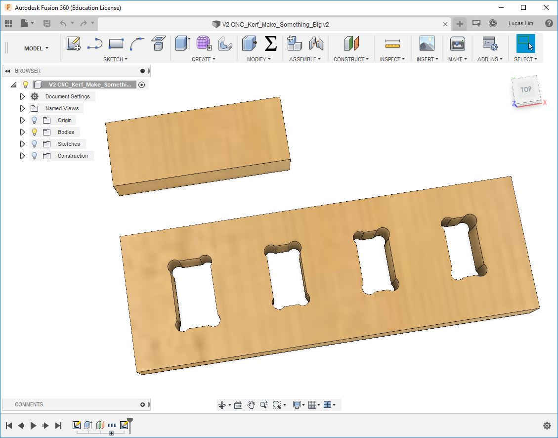
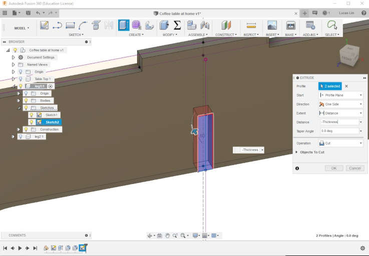
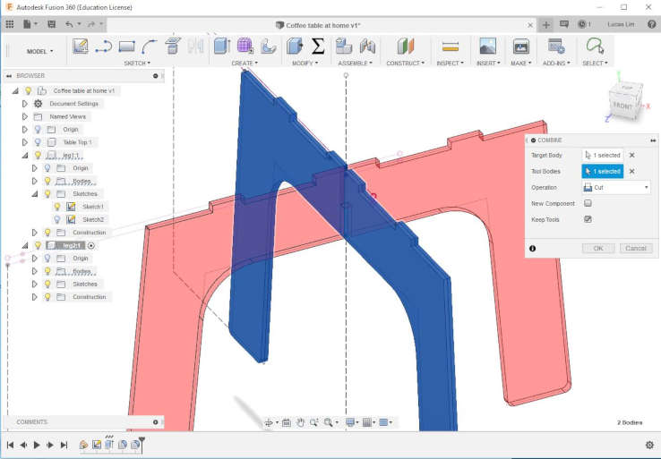
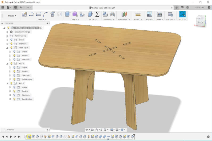
I followed a youtube video tutorial on flat-pack design of a chair " and designed a coffee table for my home using parametric design principle.
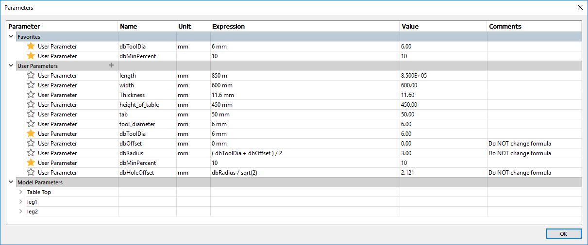
First I set some of the common items in the parametic setting. Like length, width, thickness of material, etc.
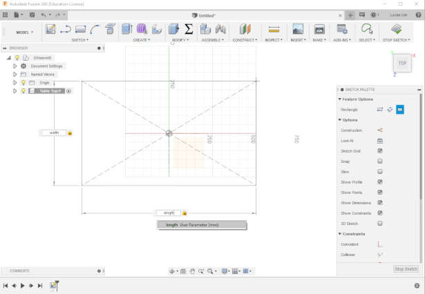
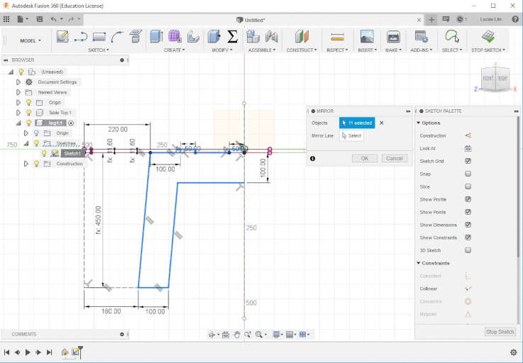
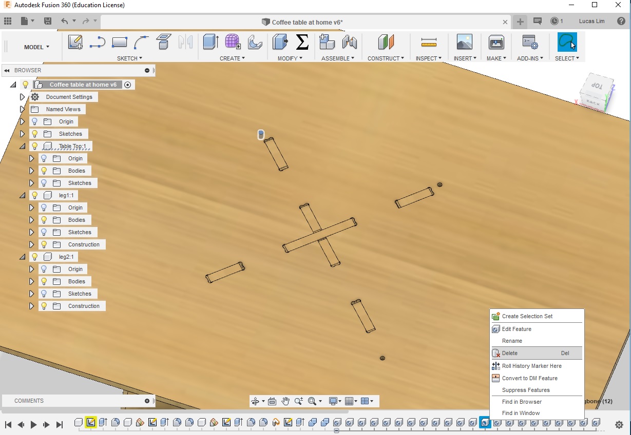
Then I drawn the table top, using the 'origin' as the centre of my rectangle. Followed by drawing the two legs and use the 'combine->cut' function to cut out all the slots. The 'combine->cut' method ensure greater accuracy in the joints.
Later I used the 'dogdone' add-in to generate the dogbones, but faced some issue.


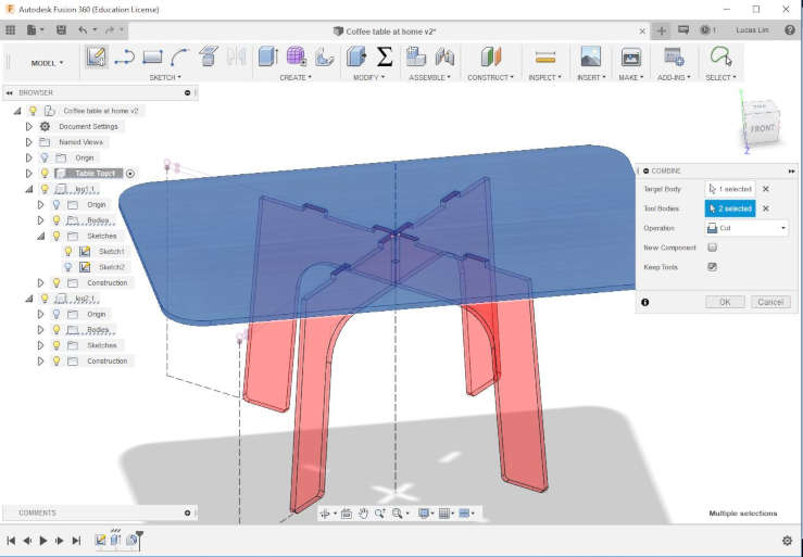
My Coffee Table :
File :
- coffee_table.f3d
- N95 Face Mask for lung and respiratory protection of the sawdust generated
- Safety glasses or safety goggles for eye Protection as wood debris can fly up toward you
- Cotton glove for handling/shifting of wood material, to avoid cut on your finger. But you might take off while operating the large format CNC router
- Ear plug or ear protector for hearing protection

- Safe Work Practices :
No jewelry,ring, or watch.
No loose-fitting clothing.
No open-toes sandals.
Tie back long hair.
Stay near to the emergency stop button and how how to operate the mergency stop.
Have first aid box nearby.
Never operate machine alone, have someone nearby


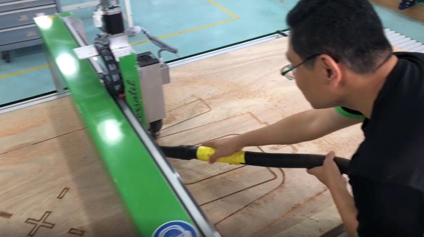

It been a wonderful learning experience for me in using the large format CNC milling machine, from the design stage all the way to the end production.
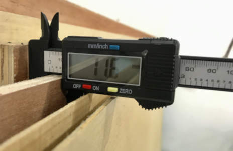
Designing the product using parametric setting came in handy. Because when I was in the Fab Lab, there was a piece of stock material already fixed on the milling machine, but the thickness was 17.7mm instead of my measured 11.6mm. The technician said to use this piece of material. Therefore I had to change my design. It was easy for me to make the change.
The milling process went smoothly and was faster than I had expected.
The offset of 0.5mm turned out to be a bit wider. I should have do another round of testing before actual milling to ensure it is a perfect fit.
- (ebook) Fundamentals of CNC Machining - A Practical Guide for Beginners
- A Rundown on CNC Router Bits and End Mills
- A Guide to CNC Bits
- A guide to understanding basic Feeds and Speeds, chipload, among other terms
- CNC Routing Basics: Toolpaths and Feeds ‘n Speeds
- What is cutting kerf?
- Autodesk Community on Fusion 360 regarding dogdone add-on
- Downlaod ofg dogdone add-on from GitHub
- Youtube video tutorial on installing and using Dog Bone Fillets in Fusion 360 (For CNC Routers)
- Youtube video tutorial on Fusion360 - Flat-pack furniture design
- Youtube video tutorial on Fusion360 - Laying out flat sheet components to prepare for CAM
- Richard A. Gizelbach, 2009, CNC Machining, Fundamentals and Applications, The Goodheart-Willcox Company, Inc. Illinois, USA. ISBN: 978-1590707906
- Edward Ford, 2016, Make : Getting started with CNC, Maker Media, Inc. CA, USA. ISBN: 978-1-457-18336-2