
Fab Academy 2019 - Lucas Lim
04. Computer-controlled cutting
04. Computer-controlled cutting
This week assignment include the use of a vinyl cutter to cut out something as well as use of laser cutter to cut out a parametric press-fit construction kit. A press-fit construction kit would consit of multiple small parts, preferably cardboard or thin wood, easily assemble/join together to form a finished product.
I started with the Vinyl cutter and then to the laser cutter.
This week I had learn the following :
- Use of bitmap tracing fuction in Inkscape (a 2D design software)
- Uee of the vinyl cutter in the Fab Lab
- Learning more on Autodesj Fusion 360
- Learning on Parametric Design
- Learning on the use of laser cutter in the Fab LAb
- Designing test part for the laser cutter
- Making my first press-fit construction kit
The Chinese character 'Fú' means 'blessing', 'good fortune' or 'good luck'. It is a common and widespread tradition for Chinese to display the Chinese character 'Fú' on the wall in the living room, kitchen or on entrance of their home during the festive Chinese New Year period. The Chinese character 'Fú' is printed on a square piece of paper (usually in red colour) and hang inverted on the wall or entrance.
1. I downloaded the Chinese character "Fú" image from openclipart (https://openclipart.org/) which is free for non-commercial use.
2. Then I used the "Trace Bitmap" function in Inkscape to convert the bitmap image (which is in .png file format) to vector graphic. For the "Trace Bitmap" setting, I had set to "Colors" Mode, and number of scans to only 3 passes instead of the default "8" as I wanted only 3 colours from the graphics.

3. After the bitmap-to-vector conversion, I moved apart/ungroup the graphics.
4. Then I refine the edges of the chinese "Fú" character by adjusting the fill and stroke to make it thicker.

4. I exported completed vector image as .dxf file and ready for vinyl cutting
My drawing file :
- My Chinese 'Fu' character in inkscape (cny_fu_sign.svg)
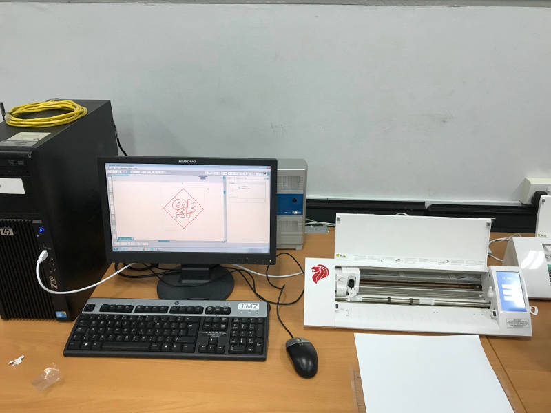
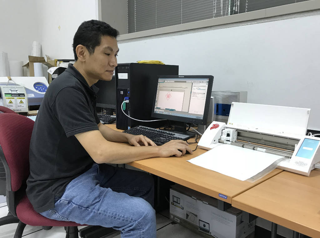
On Tuesday morning, I had went to the Fab Lab @ T12 for vinyl cutting. The vinyl cutter is a 'Silhouette Cameo' cnc cutting machine. The bundled software is 'SilhouetteStudio V3'.
Photo of vinyl Cutter Machine in T12 Fab Lab :
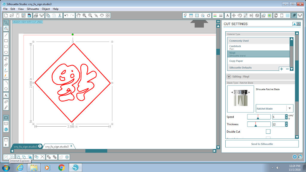
1. I loaded my artwork into the 'Silhouette Cameo' software. Check the lines/edges to ensure the lines are "single" lines and there is no abnormalities.
2. The knife selection used is number "2"

I set the following settings on the software :
- type of material to be "vinyl".
- knife selection : number "2" (which is a sharper cutting tip)
- speed : 5 cm/sec
- thickness : 12
3. Cut out a piece of vinyl and attached to the "waste sheet" or "backing sheet".
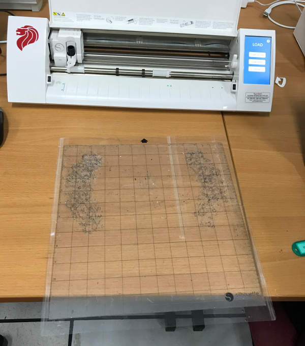
4. Test cut to determine 'knife' selection, cut setting and ability to cut to a sufficient depth of the vinyl media by simply drawing a small little "test" box and cutting that shape out. It should not cut all the way through the vinyl sheet but deep enough to be able to peel out the cut shape.
5. From the test cut, I changed the knife selection from number "2" to number "4" (a thicker cutting tip) as the vinyl media is a bit too thick and require the use of a thicker cutting tip.

5. Once testing is ok, I changed the vinyl sheet to yellow color (as our Fab Lab only have yellow colour at that moment) and send my artwork for cutting.
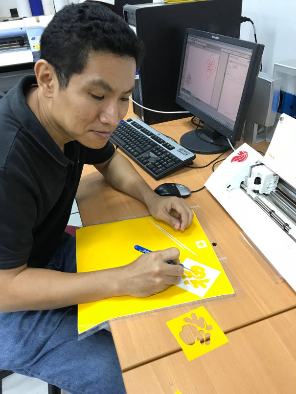
6. Once finished, I used a weeding tool to remove tiny portions along edges of design.
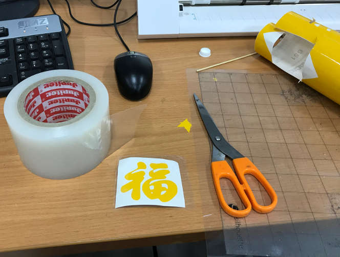
7. I cut a piece of "transfer tape" and pasted over my vinyl cut-out to transfer my artwork to the cover of my Lenovo Thinkpad notebook.
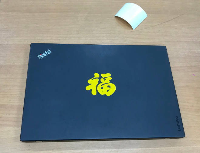
8. My first finsihed vinyl cut (a Chinese 'Fu' Character) on the cover of my notebook
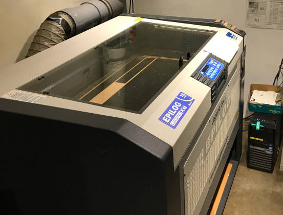
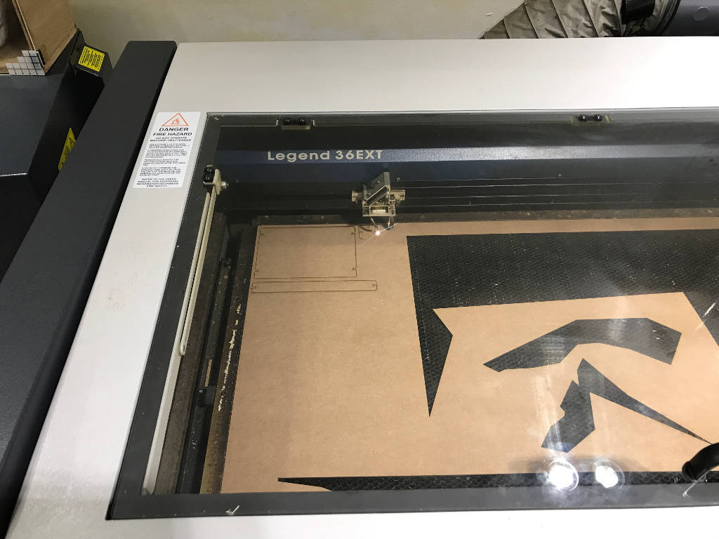
The laser cutter used is 'Epilog Legeng 36Ext', a 75watt laser cutter.
Photo of 90-watt Epilog Laser Cutter Machine at W4 Fab Lab :
I learn that parametric (model) design allow you to easily change the dimension of the shape of your model, without tediously going into the "sketch" designs to chnage each dimension manually. If your model is fully "parametric", you have a robust deisgn which allow you to be flexible to variation.
Example when you bring your design into a commercial Fab shop or to a Fab Lab to have your model cut out, unfortuantely you notice that there is a change in material thickness, or the disameter of the available cutting tool is different, but fear not if your design is parametric, you can easily change your deisgn on-the-spot to suit the "variation" required.
First step is the identifying of possible common type of variations, like material thickness, height and length of model, tab length, dismeter of cutting tool, etc., and then setting these values as "user-defined parameters" in the parametric setting of your 3D design software.
Take note that the 3D design software has to be able to support parametric feature, example Fusion 360 and Solidworks.
Design of my first parametric press-fit 3D box :
My local instructor, Mr Rodney, had provided us a simple tutorial sheet to follow, on how to draw a simple parametric press-fit 3D box.
The goal of the tutorial is to familiar with using Fusion 360, how to set the parametric setting in Fusion 360 and create a box of each side to be 60mm to 60mm made of either plywood (thickness of 2.5mm) or acrylic (thickness of 3mm).
Later, he had demostrated that by setting up a parametric model of the 3D box allow easier scaling of the model, like if you want it to be bigger or smaller or to adjust the thickness of the material (2.5mm, 3mm, etc).
1) Parametric setting in Fusion 360 :
Create 'User Parameters' for thickness of each side: 60mm, length of each tab: 20mm and thickness of material: 2.5mm.

(2) Drawing of 3D box :
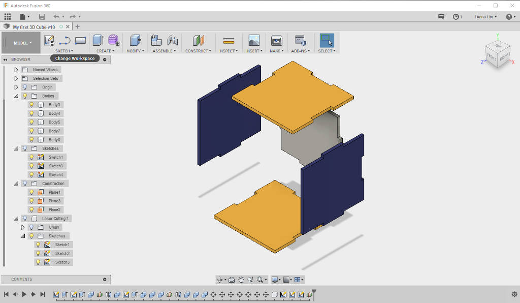
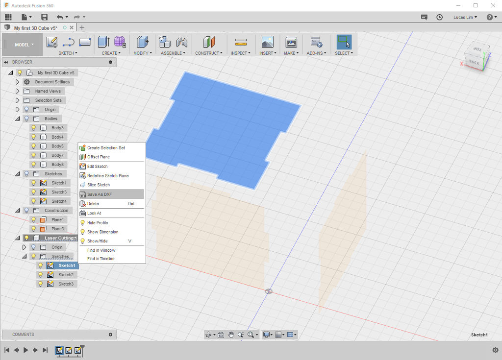
(3) Extracting out the unqiue sketch 'surface' and export out as .dxf files
Refering to Laser Cutting Machine Vendor's guide on the table of recommnded cut setting. I played around to determine the most ideal cut, to find a sweet spot of the cut setting for my cardboard material.
Refering to Vendor's guide on laser cutting setting for different material :

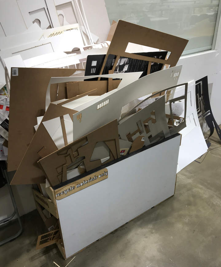
I used part of the recycled material left-over by previous students to cut out "test" boxes to determine the "kref". The amount of material needed is quite small for the test boxes.
I played around with laser cutting setting, taking into consideration not to apply too much power (as the effect of stronger laser heat will result in an unecessary amount of "kerf") and keeping the rate (pulses per minutes) to be 300 or 500'
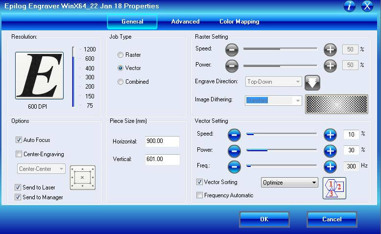
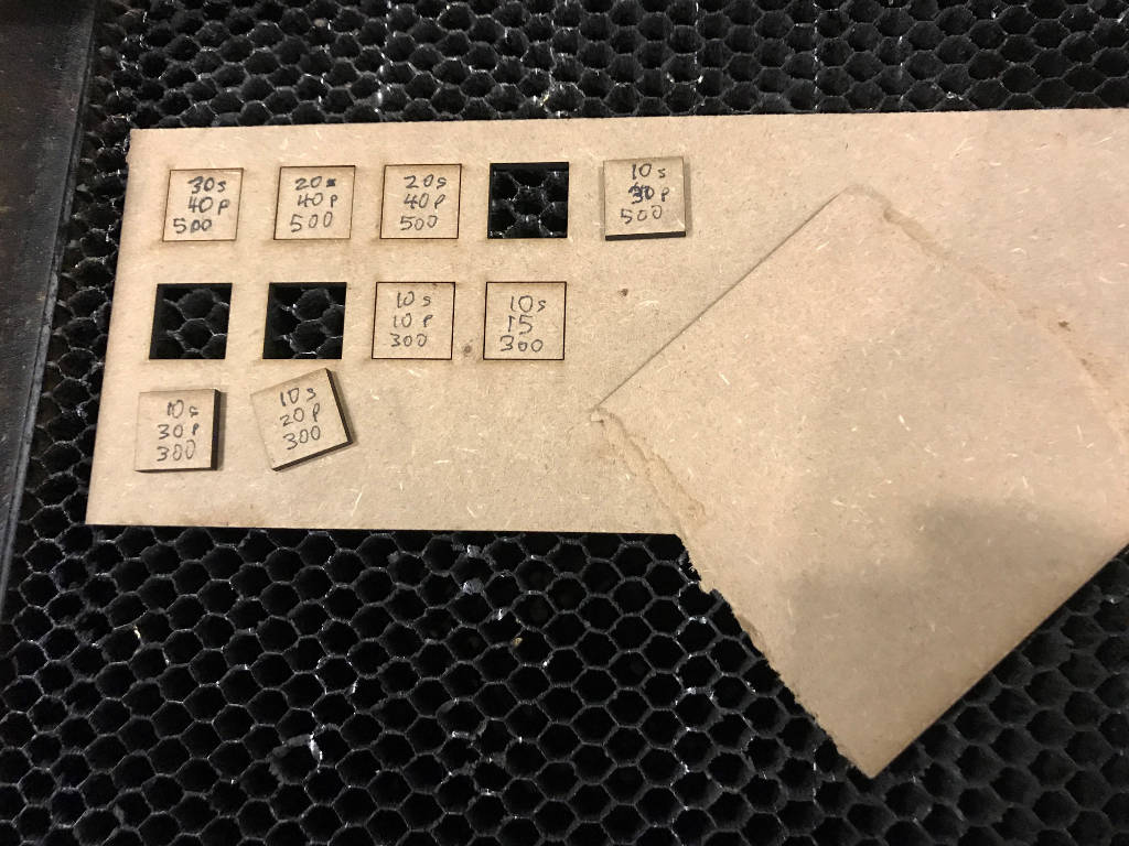
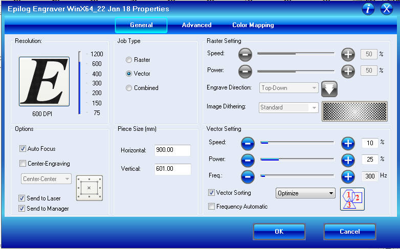
My ideal laser cutting setting :
- Speed : 10%
- Power : 20 %
- Frequency : 300 Hz
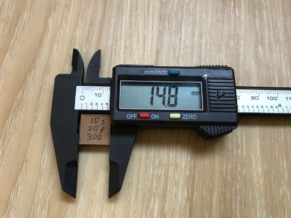
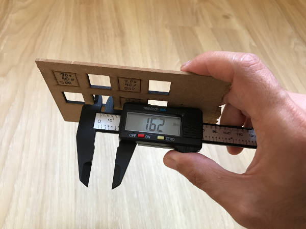
I used a Digital Electronic Vernier Caliper Measuring Tool with LCD Display to measure the test-box and the "slot" or cut-out hole. The kref was found to be "1.4mm" (16.2mm - 14.8mm)
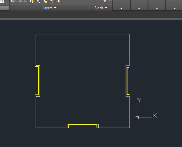
I then imported the (2D) .dxf file into Autodesk AutoCAD 2016, as was available on the computer in the Fab Lab and made the adjustment for the kref.
Steps:
- Imported the .dxf files into AutoCAD
- Explode the 'block' into individual line
- Intending to only adjust the 'slot' portion. I used 'offset' command, set the distance I want to offset and click on the lines of the 'slots' to extend it out. As the slot have "left" and "right" (oppposite) sides, so my offset measurement used is "kref" divided by 2, which is 1.4mm/2 = 0.7mm.
- Use the 'block - create block' command to group it out
- Saved the .dxf file
- Went back to the laser cutter and cut my pieces out
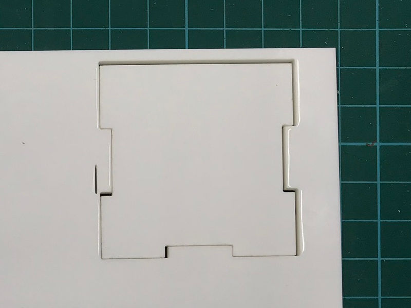
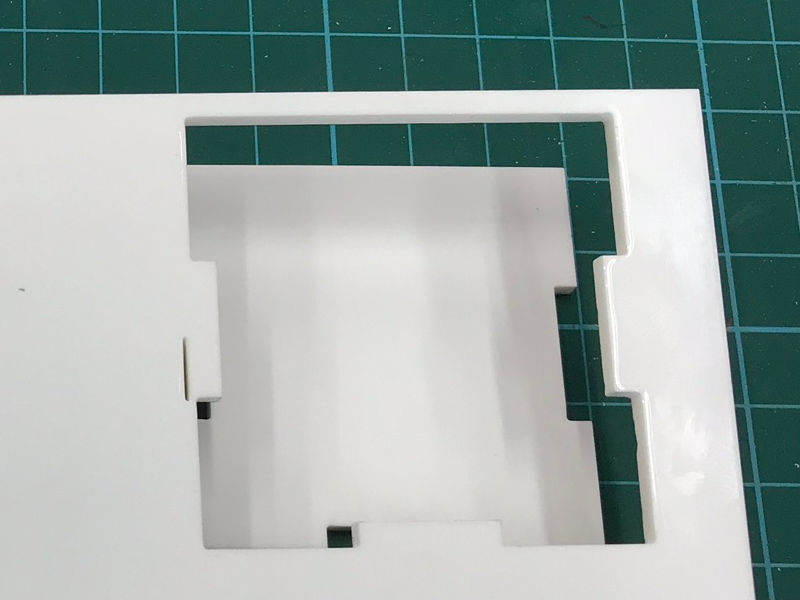
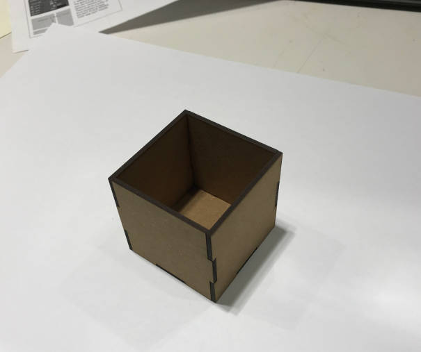
My completed first parametric press-fit 3D box :
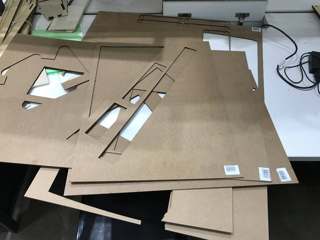
I embarked on another pressfit construction kit project that would incorporate multiple slot-in pieces as well as the concept of using chamfered joint at the openning that was shown by Prof. Neil during lesson.
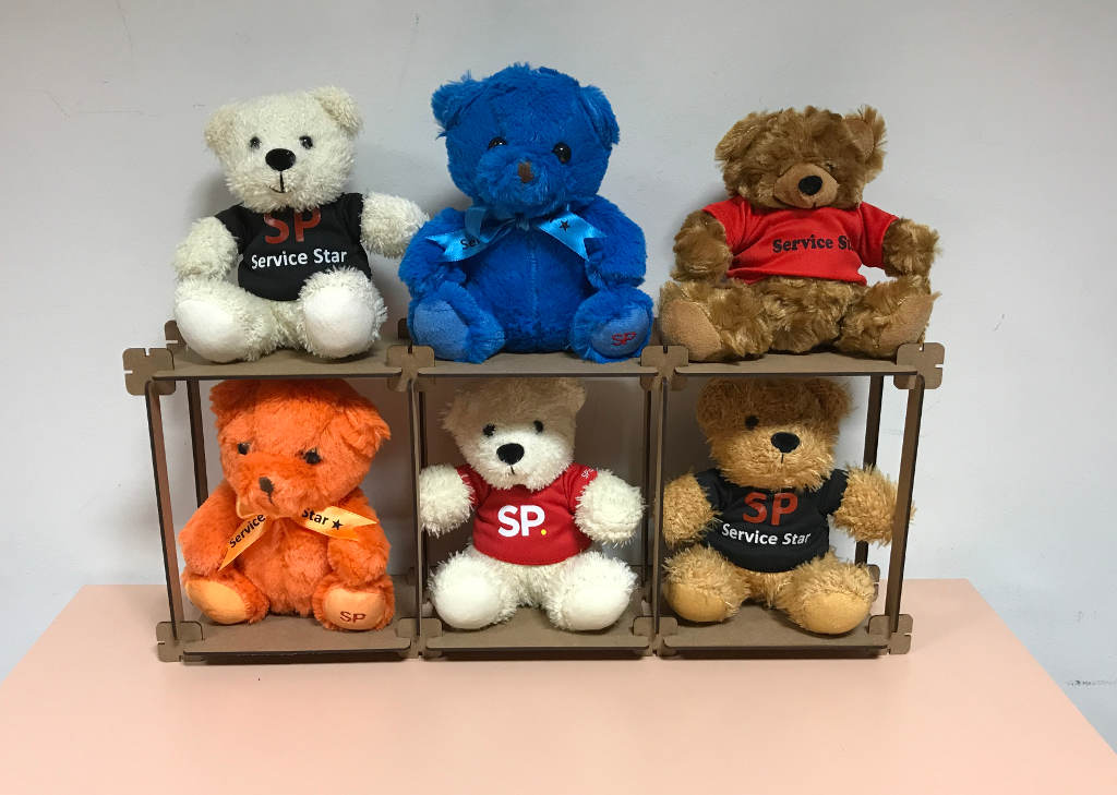
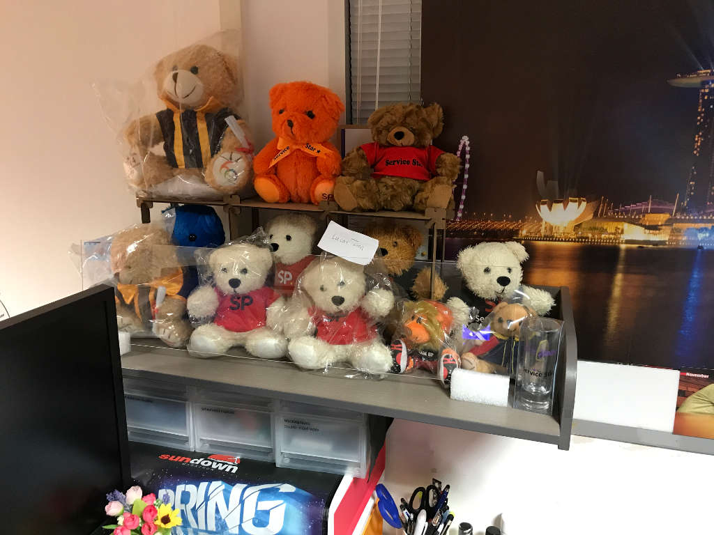
I looked around my office for ideas, as I wanted to make something useful. So I decided to make a small shelving unit for my soft toys. I have many of these teddy bears as they are given to me as part of the Singapore Polytechnic Service Excellence Awards; one teddy bear for each quarter of the year.
Considerations for Small Shelving unit :
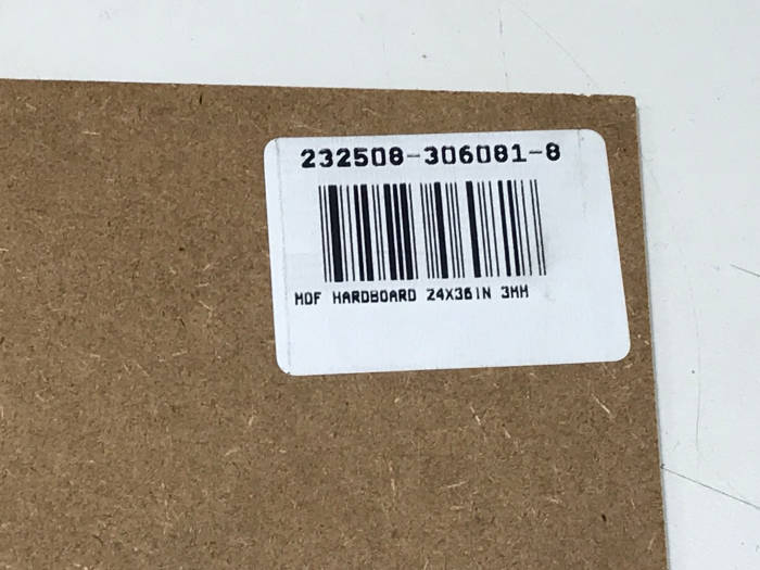
The material used was 3mm think medium-density fibreboard (MDF) hardboard left behind by the students in the recycled bin in the Fab Lab after their cutting. I choose the 3mm thk MDF hardboard over the 2.5mm thk white-colourcardbaord, as it is visually appealling and strong enough to support the light-weighted teddy bears. The 3mm thick MDF hardboad is thicker than the 2.5mm one that I used for my 3D box earlier.
1. Looking for suitable material at the Recycled Bin at the Fab Lab at the School of ABE, which I am supporting and near to my office. All these recylced material will be disposed off after the end of each school term, so I am makin use of these material before they are dispose in another two or three weeks time.
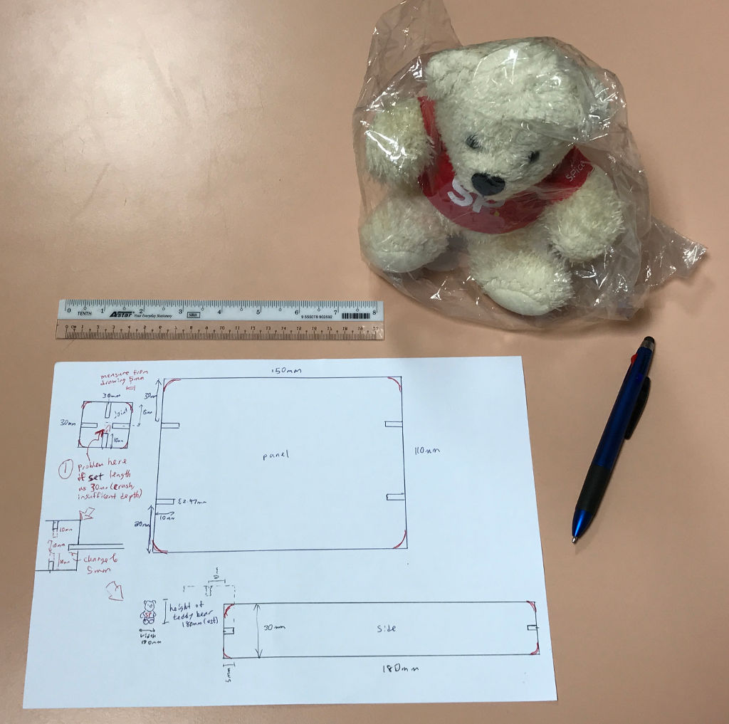
2. Initial design concept
I started stetcing out my idea and initial design on a piece of paper. Drawing out the parts with the measurement taken using a ruler (on a scale of 1:1) allows me to visualise how the final product will be like and make any changes/corrections at an early stage. Changes/corrections were marked out using red colour pen to indicate my changes helps for easy reading.
One of the problems identifed is at the square-joint piece, the length of the square-joint piece is 30mm (at each side), if I were to used a slot-depth of 10mm, there will be a crush with the other two pieces when they are being slot in, so I changed to slot-depth to 5mm.
3. Finding the characteristics of the laser cutter and the MDF hardboard material
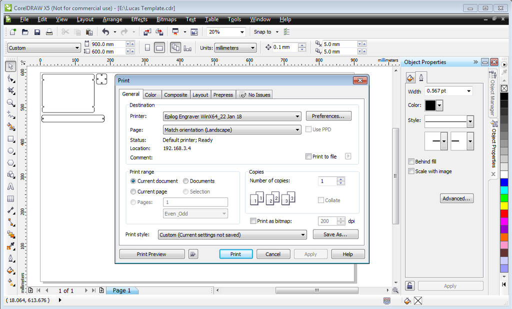
The Epilog dashboard printer driver has been installed on a PC connected with the Epilog laser cutter. The operation is very user-friendly just like sending a print job to a normal printer. The software use was Corel Draw.
Based on the speed and power recommendation guide provided by Epilog and earlier laser cut for the 3D pressfit box using the same MDF hardboard material (2.5mm thk). I started doing some tests to look for the ideal cut setting to use for the 3mm thk MDF hardboard. I drawn the test boxes using Fusion 360.
References : Owner's manual for Epilog Legend 36EXT
File : Test boxes .dxf file


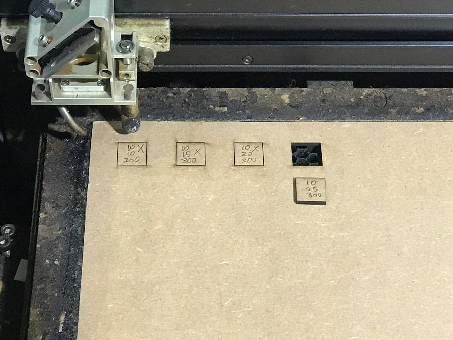
Test Result :
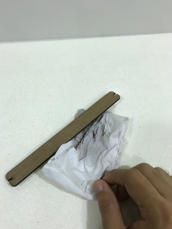
4. Finding the 'kerf' by making a parametric test comb
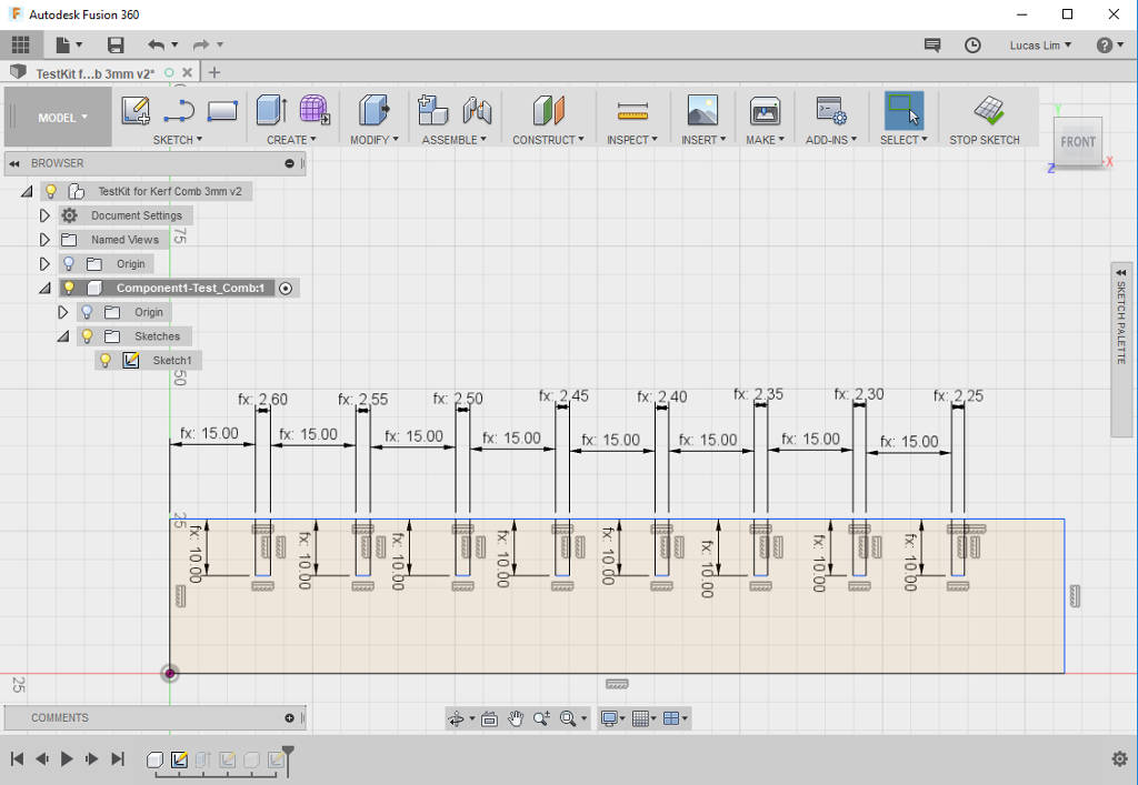
The thickness of the MDF hardboard used is 3mm. I drawn out a simple parametric test comb with a number of 'slots' of reducing measurements for each slot. I had drawn the test comb out using Fusion 360 instead of Corel Draw software on the laser cutter computer, which doesn't support parametric modelling.
The first slot starts from 3mm width (which is the thickness of the cardboard material) and slowly reduce by 0.05mm with each subsequent slot. After which, I used a same piece of the same material to slot into each slot until I find my ideal "tight fit".
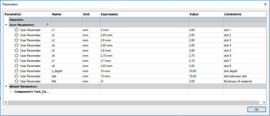
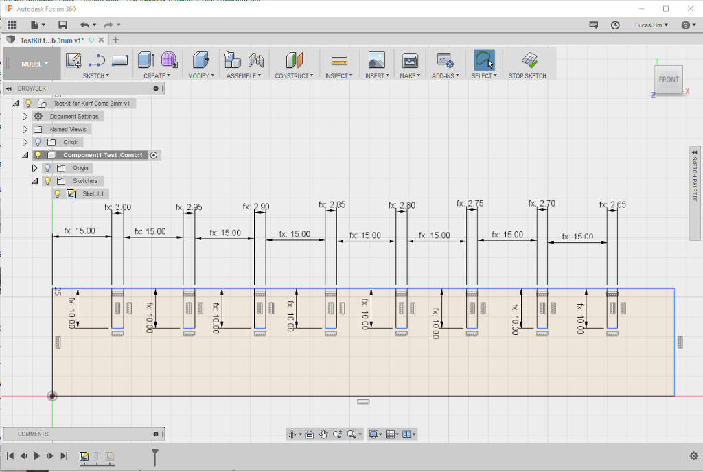
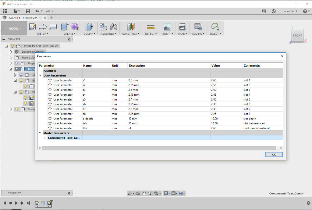
Parametic model of the test comb make it so easy for me to adjust the slot-width again :
As the kref seem to be bigger this time. I adjusted the width of my staring slot to be 2.6mm down to 2.25mm
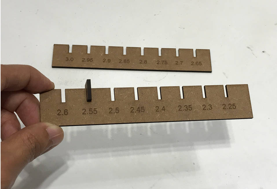
From the test result, the kerf, which is the amount of material removed by the laser cutting process, is found to be 0.45mm and the ideal width of the openning of my pressfit slot is 2.55mm.
File : Parametric Test Comb in Fusion 360 .f3d file
5. Drawing in Fusion 360
I used Fusion 360 to draw out my design for the parametric press-fit small shelfing unit.
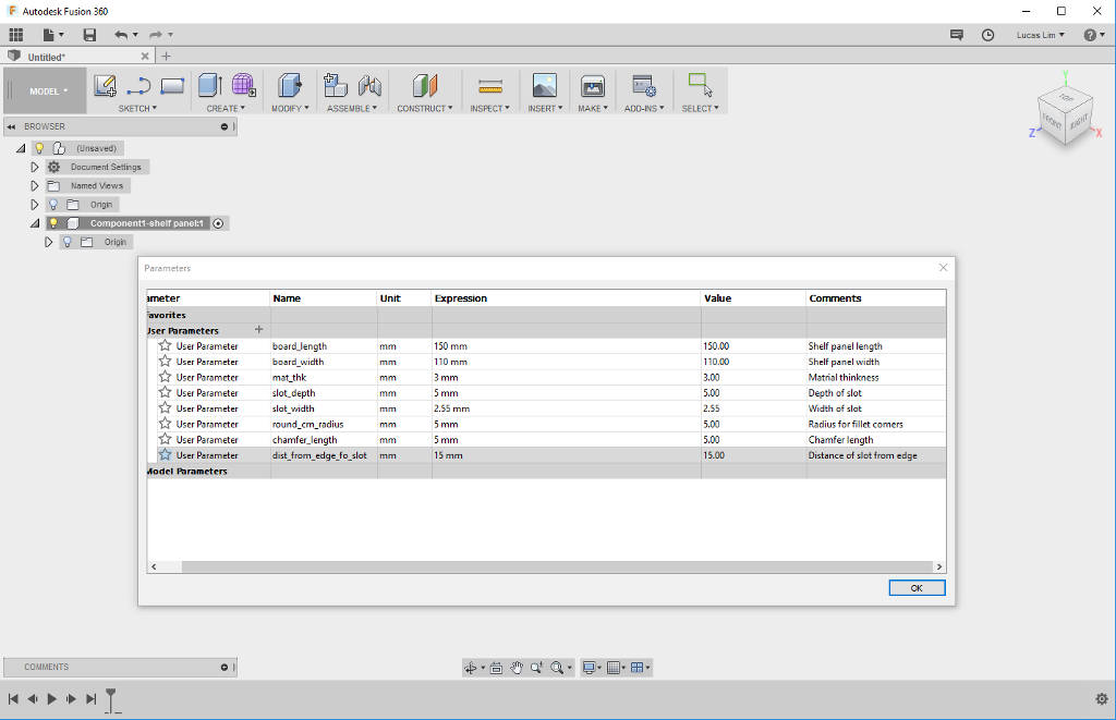
Typing in parametric values and draw out the design by selecting the parametric values :
Some of the parametric setting set up are :
- length of the board/panel piece
- width of the board/panel piece
- depth of slot
- width of slot
- radius of round corner
- etc. (as I slowly added in later on when drawing the other pieces)

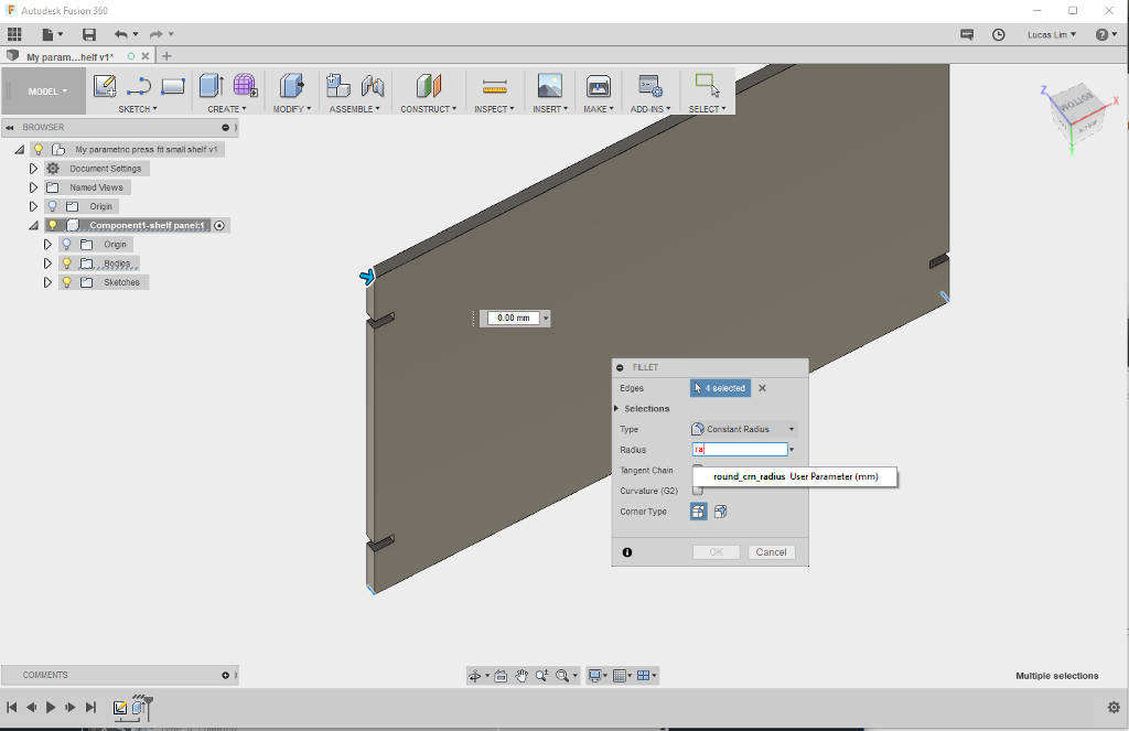
Creating rounded (fillet) corner for all the edges and exploring the chamfer joints :

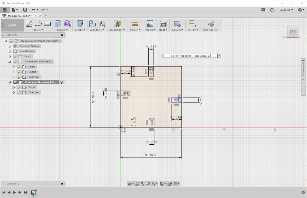
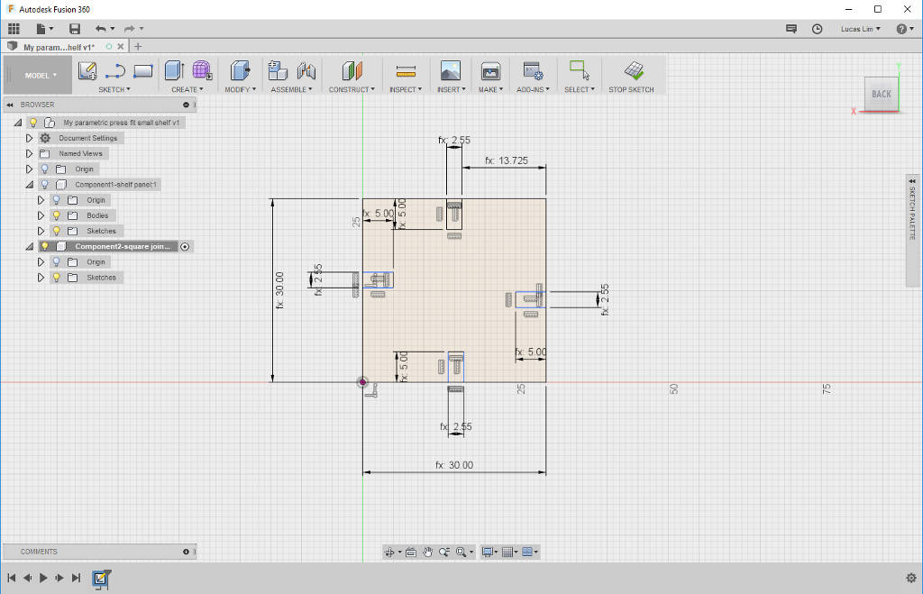
I am new to using Fusion 360, during the deisgn of my square joint, I had wondered on how to make the placement of all my slots dynamic. The slots are to be positioned at the mid of the length of each side of the square joint. Solution : I had created a formula, sq_joint_mid_length - (slot_width/2) which will place the slot at the mid and is dynamic. Fusion 360 does not seem to allow nested or complex formula, so my value for sq_joint_mid_length is manually calculated and entered into the pararmetric screen.
Drawing of the side pieces, using the same concept mentioned above to position my slots dynamically at the mid of the width of the side.

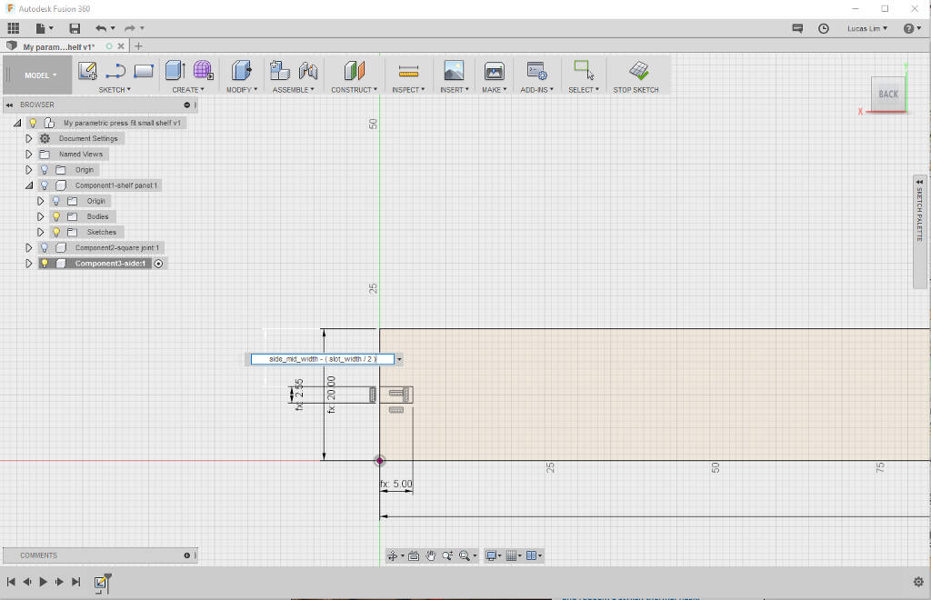
I was experiment with two types of joints. On the board, are the improved slot-in joints with chamfered opening. On the side piece and square joint piece, are straigh hard joints.
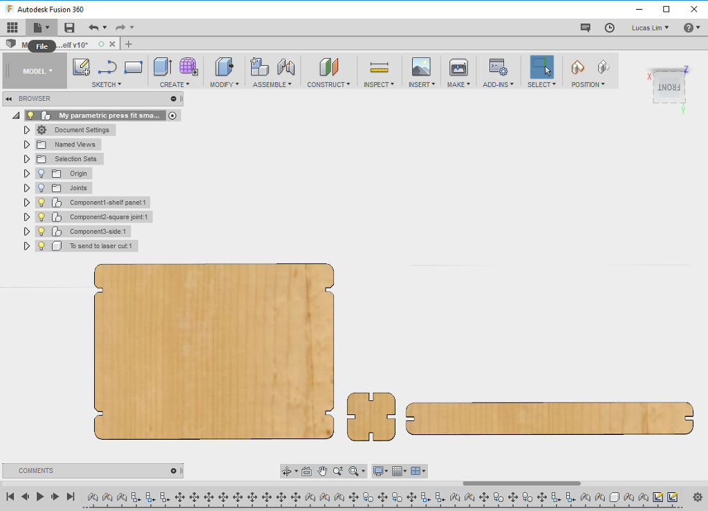
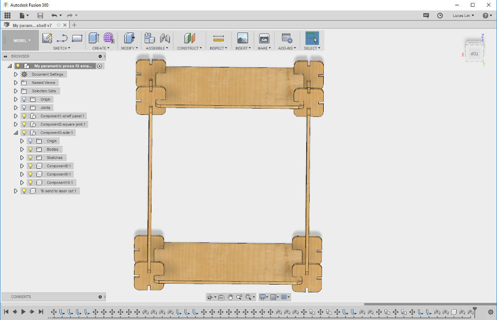
Completed design of my parametric press-fit small shelving unit using Fusion 360. Using the "Material" function to add "pine" colour and texture. Using the assembly function to connect the pieces to have a look at my finished design as well as enable me to do a visual check on all the joints and pieces.
File : My parametric press-fit small shelving unit design in Fusion 360 .f3d file
1. Import the .dxf files into Coral Draw and send to laser cut. As a precaution, I only cut out one of each of the three unquie pieces (board, square joint and side).
Laser cutter setting :
Speed : 10%
Power : 25%
Frequency : 300Hz
The three pieces tested ok. Ready for (mass) production of parts.
2. Post-cutting cleaning of the edges to remove the ashes.
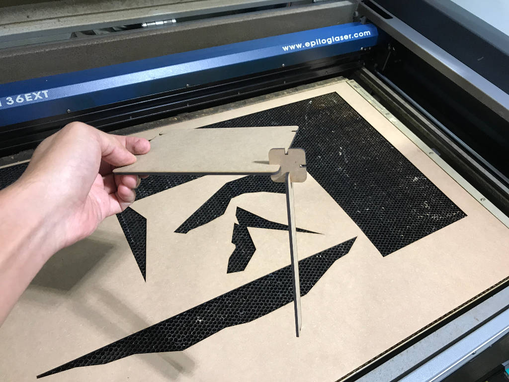
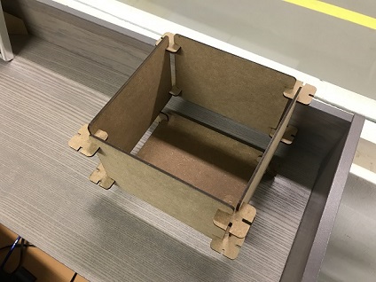
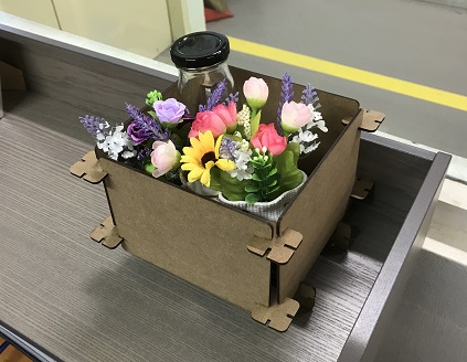
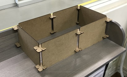
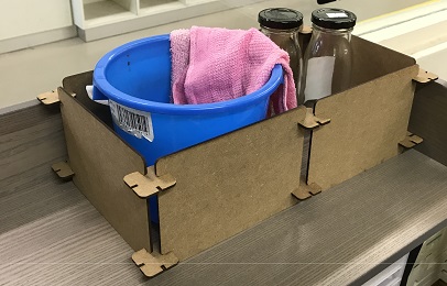
3. My first press-fit shelving unit.
4. Playing around with assembling the parts in multiple ways.

Vivyl Cutting :
Vinyl cutting is fun, I want to print more stickers for my work, example safety logos on equipment, etc.
Laser Cutting :
Going fully parametric on my designs for the test comb and press-fit construction kei, although it take some effort at the initial stage, but it definitely worth the effort. Parametric setting allow you to easily make correction to your design later on, as well as allowing your design to scale-up or down easily.
- My Chinese 'Fu' character in inkscape (cny_fu_sign.svg)
- 3D Box design, in Fusion 360
- Parametric Test Comb for testing kerf, in Fusion 360
- My first press fit construction in .f3d file
- How to vectorize in Inkscape (by Aaron Nieze | January 13, 2015) http://goinkscape.com/how-to-vectorize-in-inkscape/
- Video Tutorial on understanding how Laser Cutter work on Youtube : Fab Academy 2015: Lecture03 Laser cutting
- Video tutorials on Learning Fusion 360 on Youtube :
- Tutorials for absolute beginners on Autodesk Fusion 360 by Lars Christensen
- "How I use Sketch Constraints and Dimensions — Fusion 360 Tutorial — #LarsLive 113"
- "Designing a Lasercut Laptop Stand with Fusion 360"