Giada Allocca
This is my website for the Fab Academy
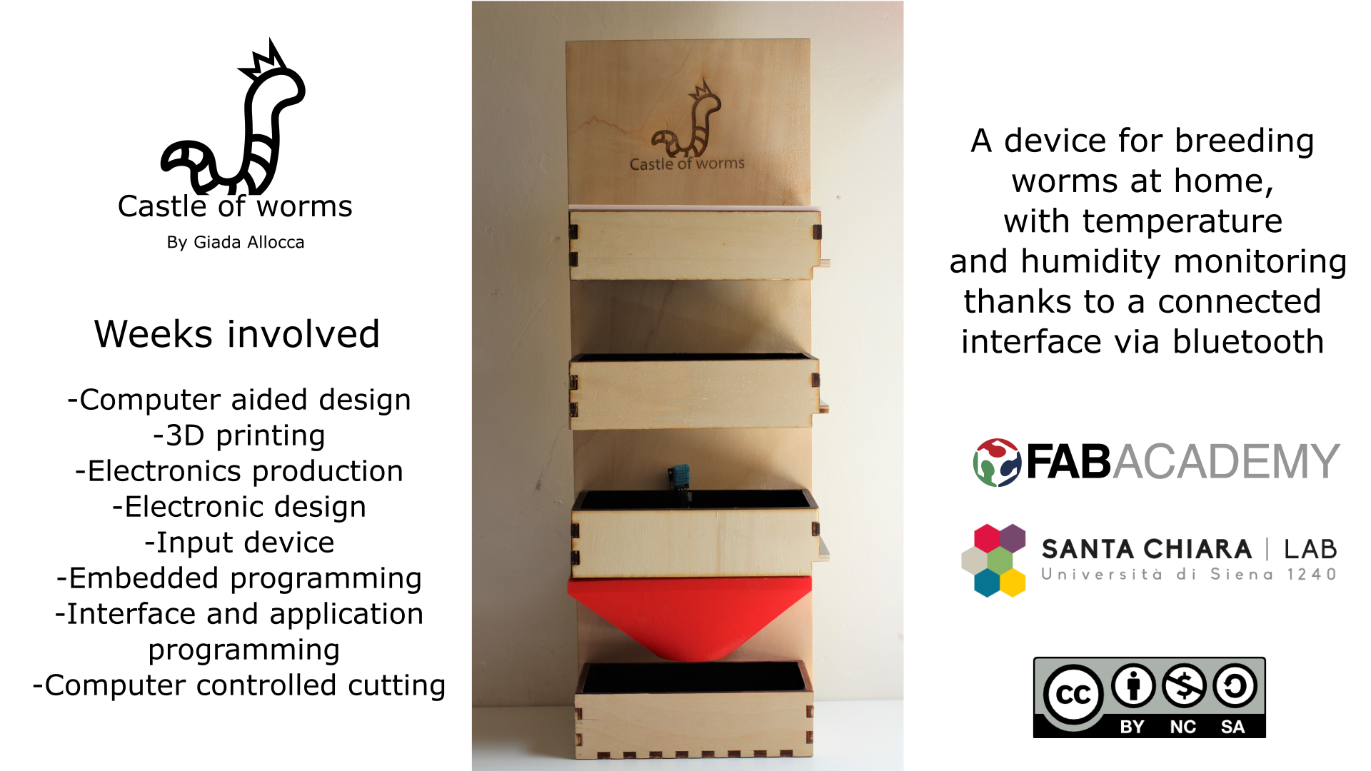
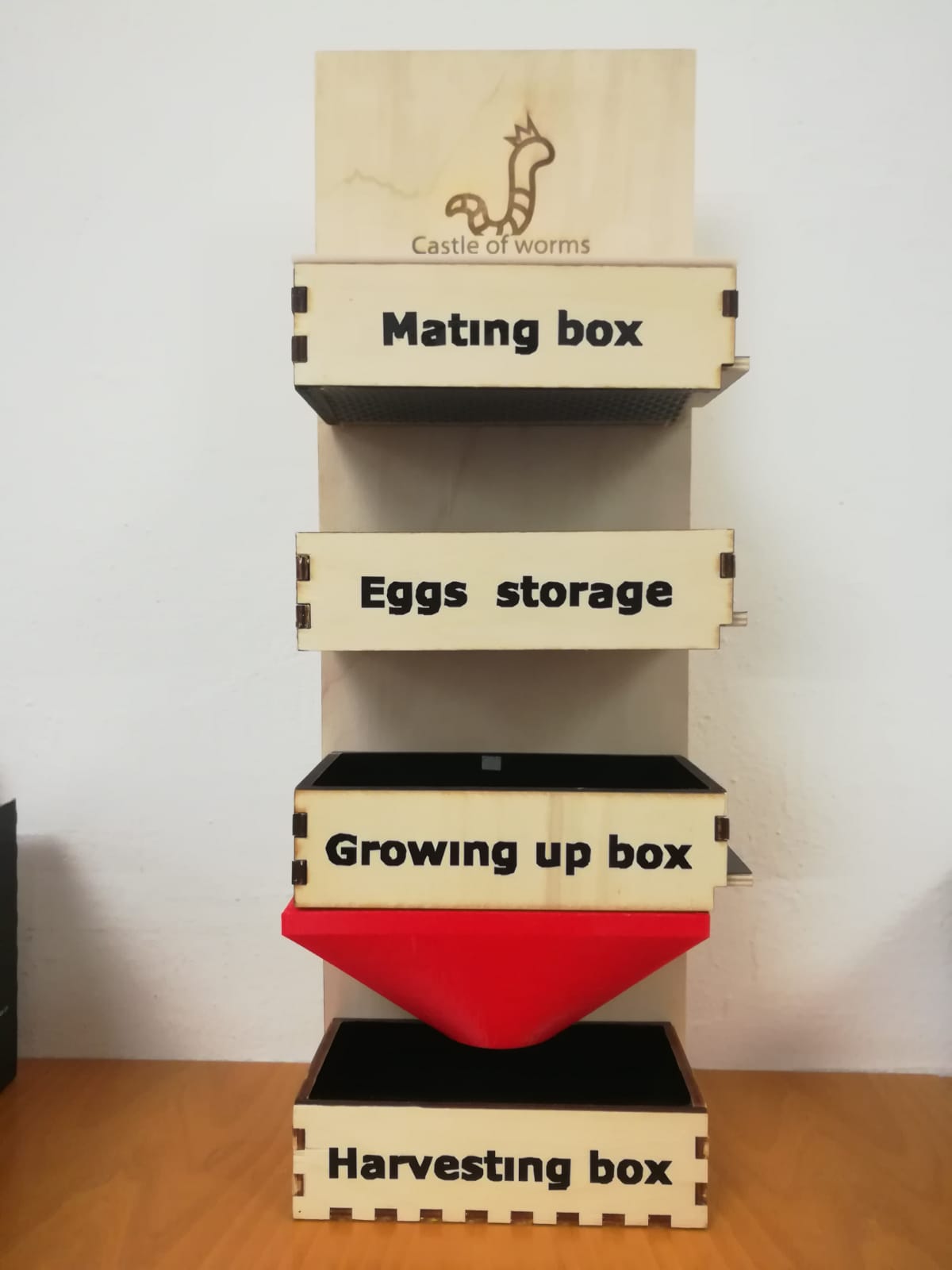
Final result
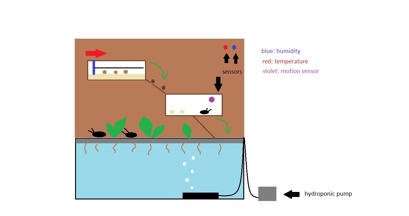
The concept
- Sustainable management of water for arid and semi-arid areas;
- Sustainable farming systems under Mediterranean environmental constraints;
- Mediterranean food value chain for regional and local development.
Schedule
Computer-aided design
Computer-controlled cutting
Electronics production
Electronics design
Input devices
3D printing
Interface and application programming
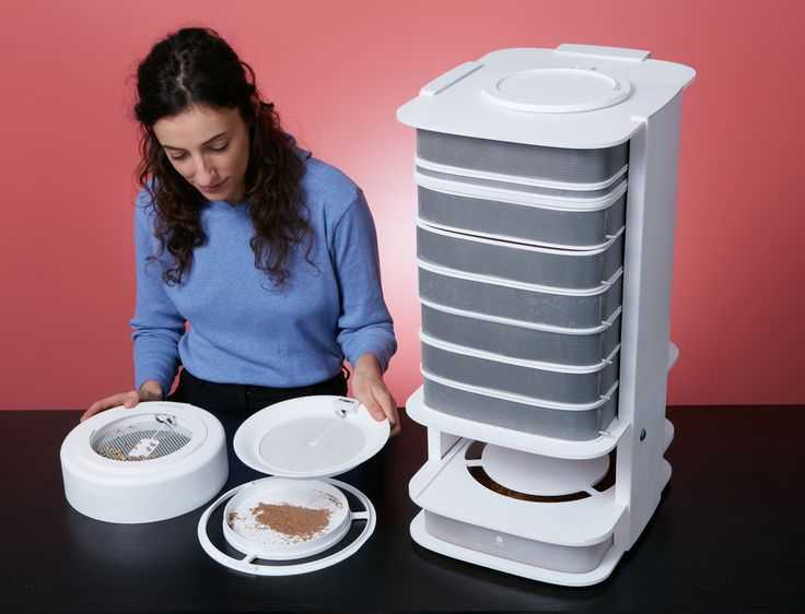
State of art
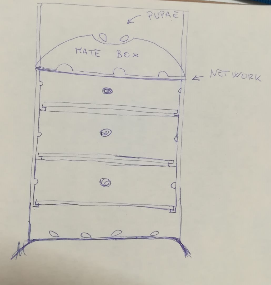
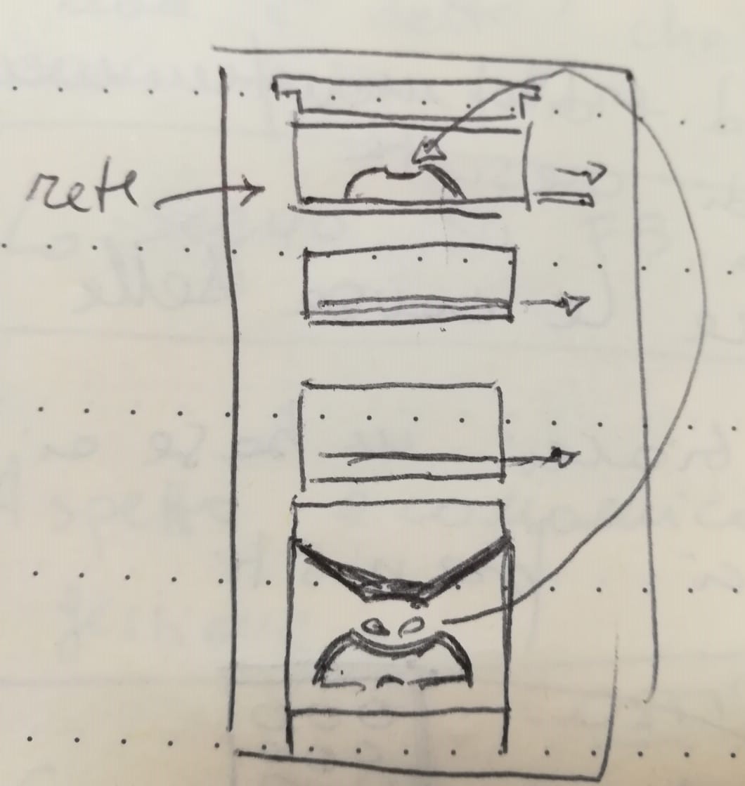
Sketch

Update 15/04/2018
Update 09/11/2018
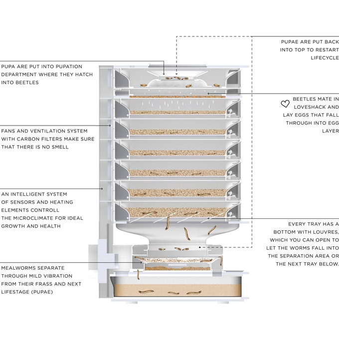
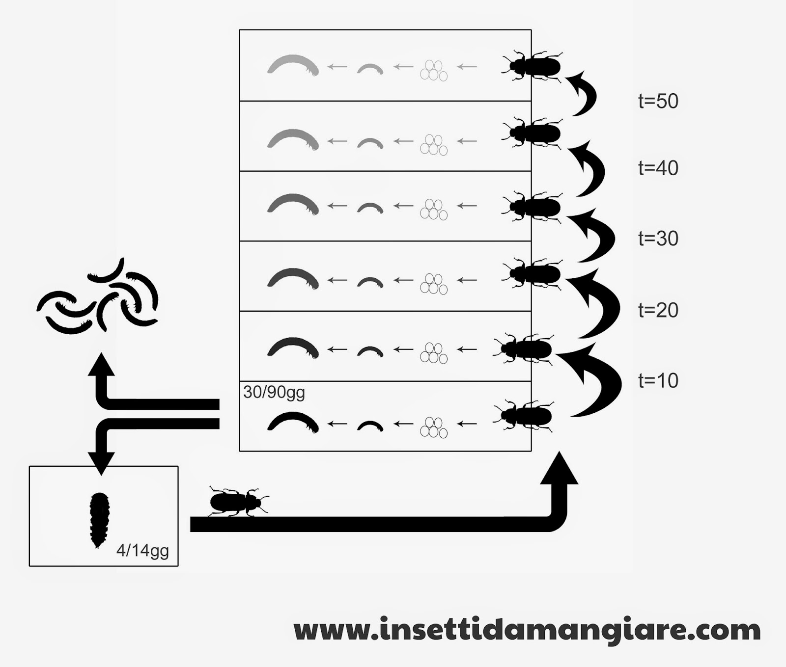
Moreover, the first box will have a perforated cover to let the air pass and prevents beetles from flying away. The eggs will pass to the second box where they will grow, then they will be moved to the third box (to allow the eggs of the first box go down to the second one). Under the third box there will be a sort of funnel that will channel worms and pupae into a dell, where the worms will come down and the pupae will remain. Now it is appropriate to move the pupae in the dell of the first box, so the cycle will starts again.
But who would use this product? Food consumption of insects and worms is still low in our part of the world, at the moment only elite chefs have started using them in the kitchen. Hoping to become the next fashion in the kitchen, this product could interest anyone who wants to have a healthier diet, without renounce the protein of meat but at the same time helping the planet not wasting water and not emitting CO2. Buyers can be families but also exotic restaurants.
Hardware
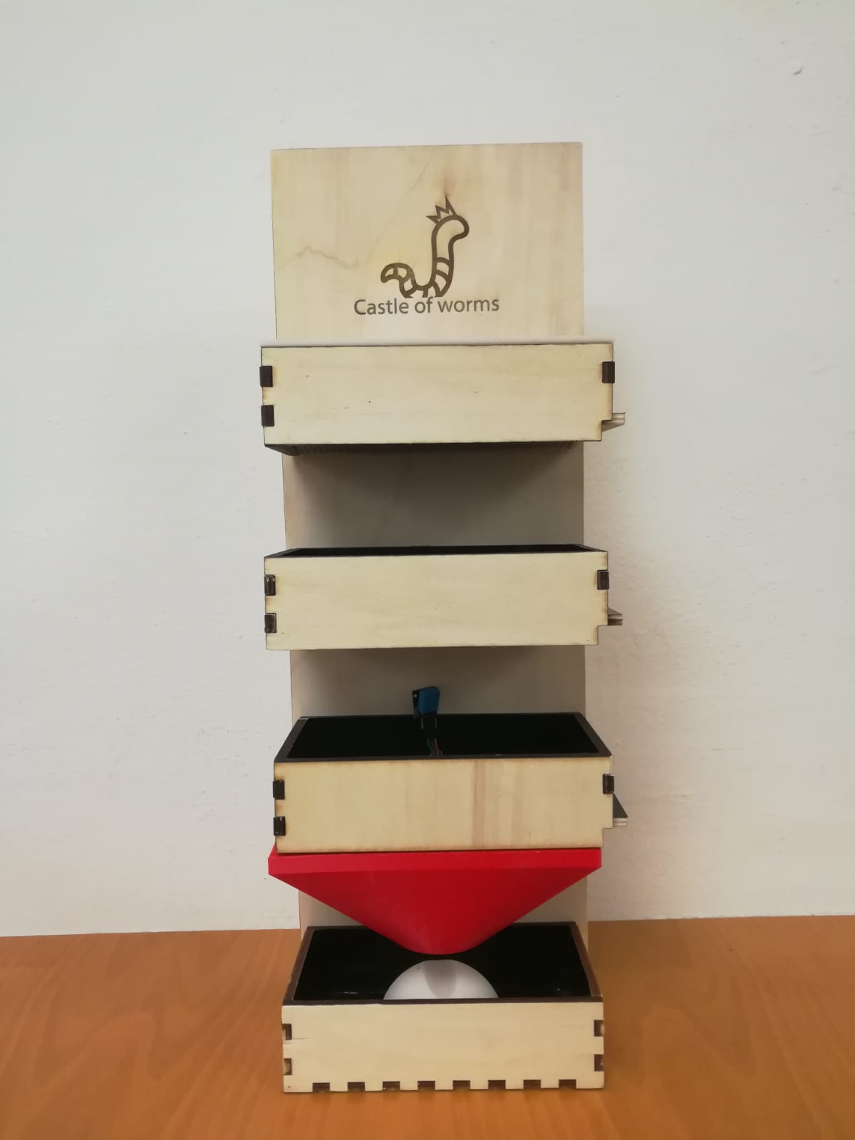
The idea of the project is based on a sort of chest of drawers, the most used method by worm breeders. The structure will be vertically with 4 boxes: the top three will have a movable bottom that will be activated manually while the last one will have the function of collecting and base of device (to create stability). The first box will have a perforated lid. To get an idea of the final result I created an assembly with the various parts. I made the models with Solidworks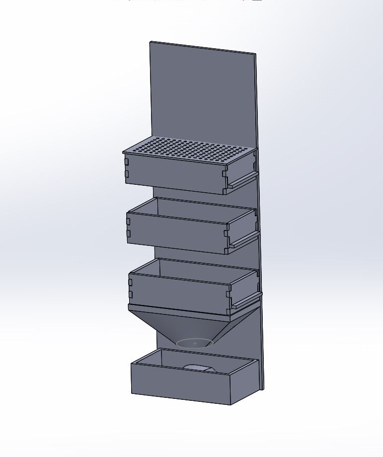
First of all I created the boxes, this is the one with movable bottom.
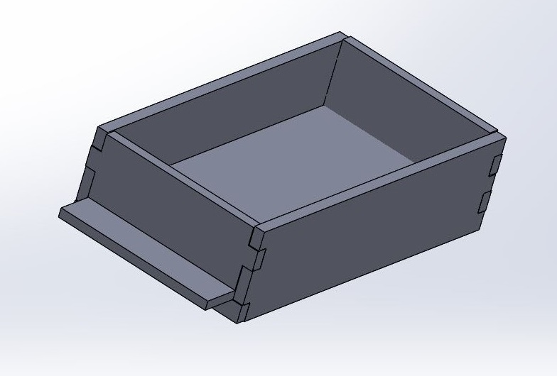
After laser cutted the sides of the box I glued some wooden guides to slide the bottom. I finished the sides of the bottom with sandpaper to ensure smooth running.
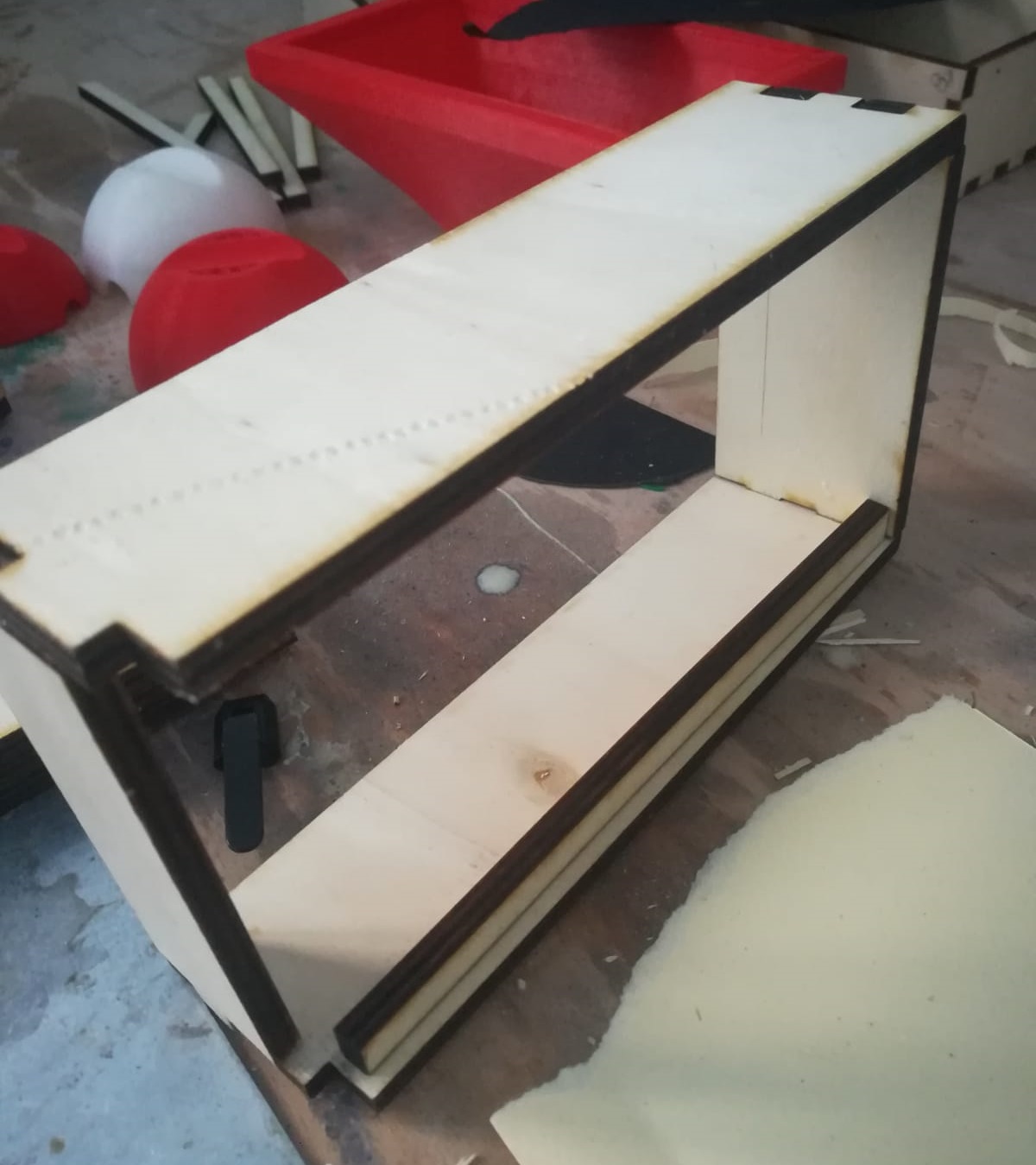
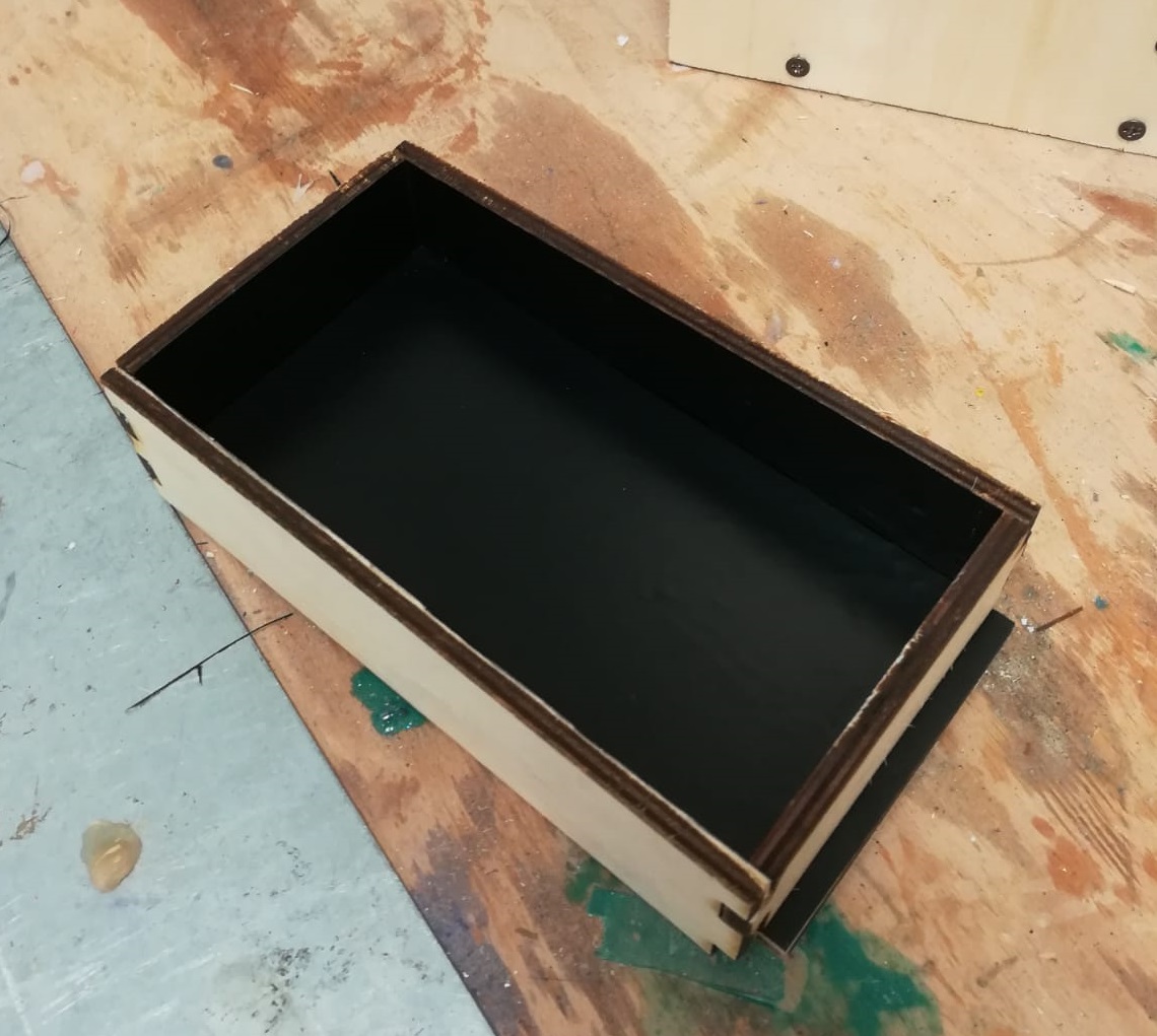
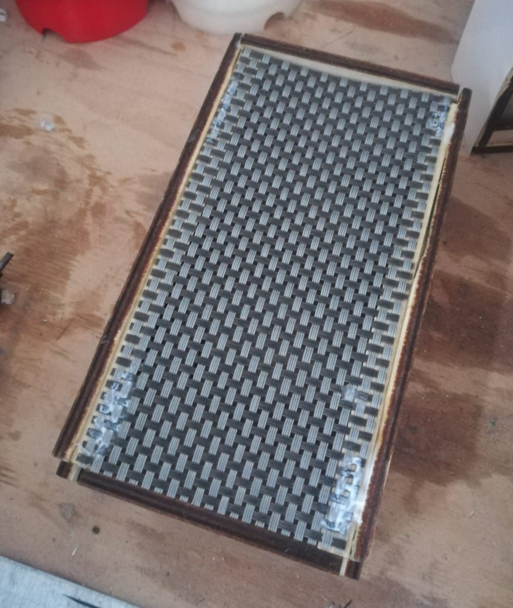
Once the glue has dried I have finished the boxes with the vinyl sheet, in this way the worms can not climb to escape and I must say that even aesthetically it is not bad. Those processes was made for three boxes.
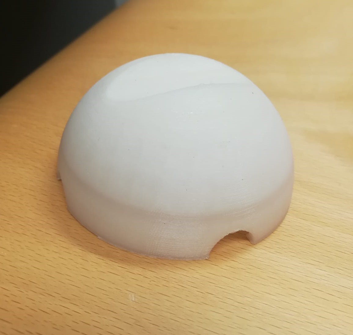
On Solidworks I made various parts of my project. This is a little dome where the beetles will mate and lay eggs. There is a dell at the top to accommodate the pupae and holes at the bottom to let the beetles enter. I was careful to take the measures to make sure it entered in the box. I printed 2 domes, one for the first box and one for the last.
 |
 |
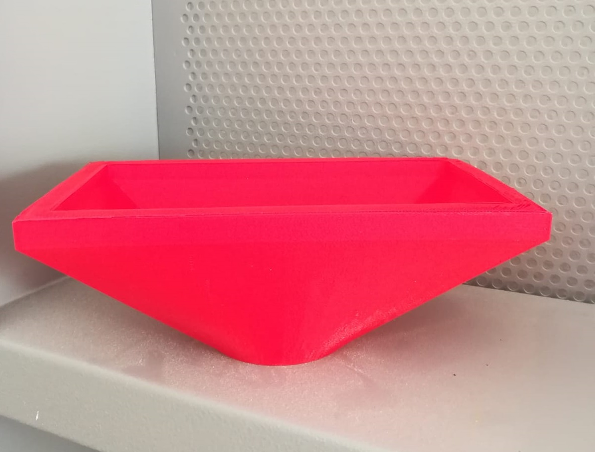
Under the third box I thought to make a funnel that brings the worms into the dimple above the dome that will be in the last box.

The bottom part
The above part
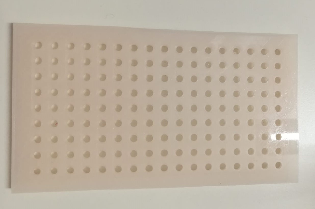
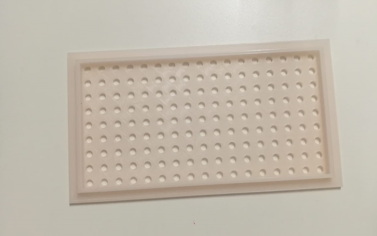
The first box has a net to allow the eggs go down to the next box and avoid the dome fall down with the beetles. The network that I used is only representative, ideally the network should be more like a mosquito net. I placed the net above the guidelines of the movable floor.
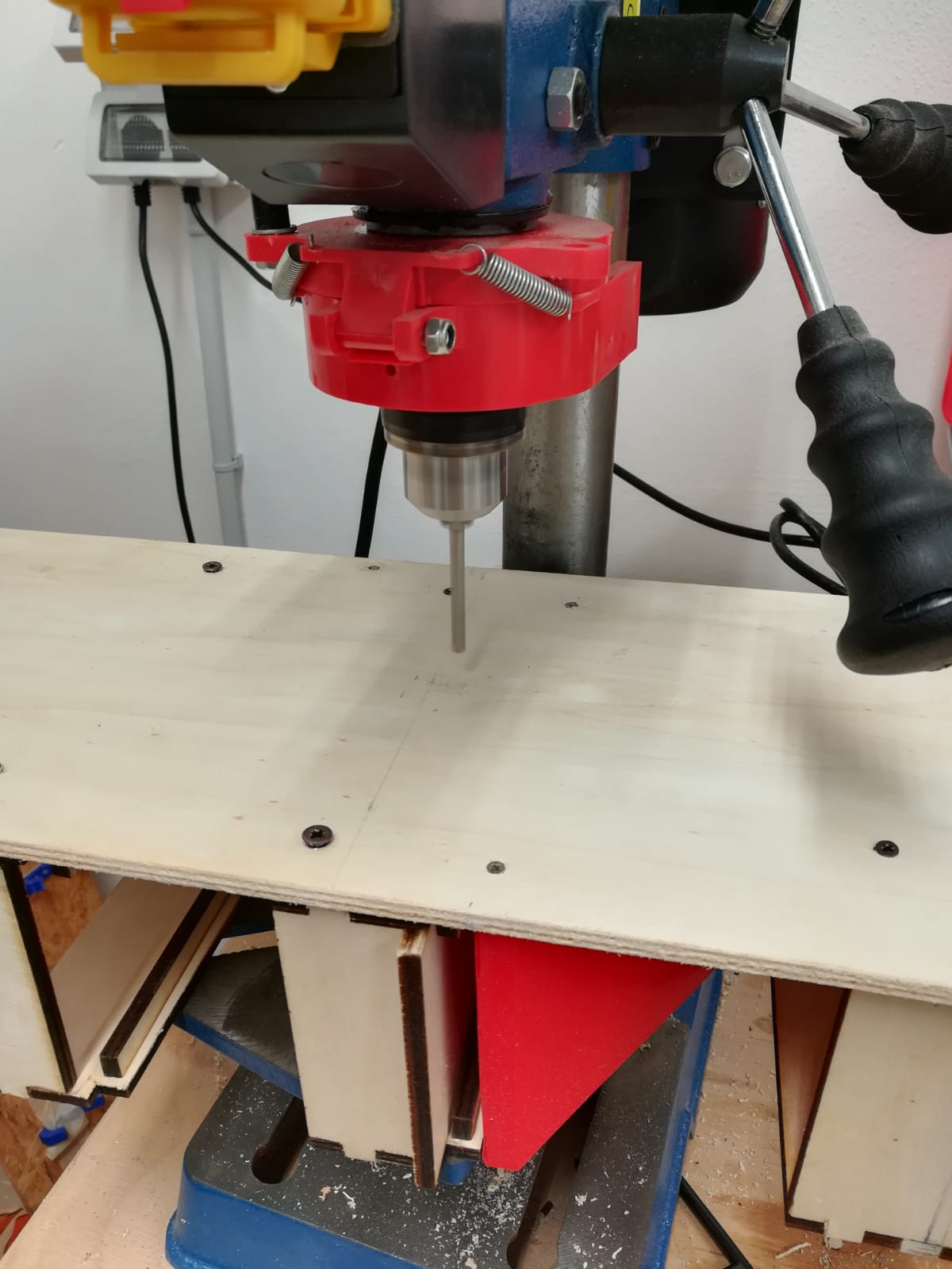
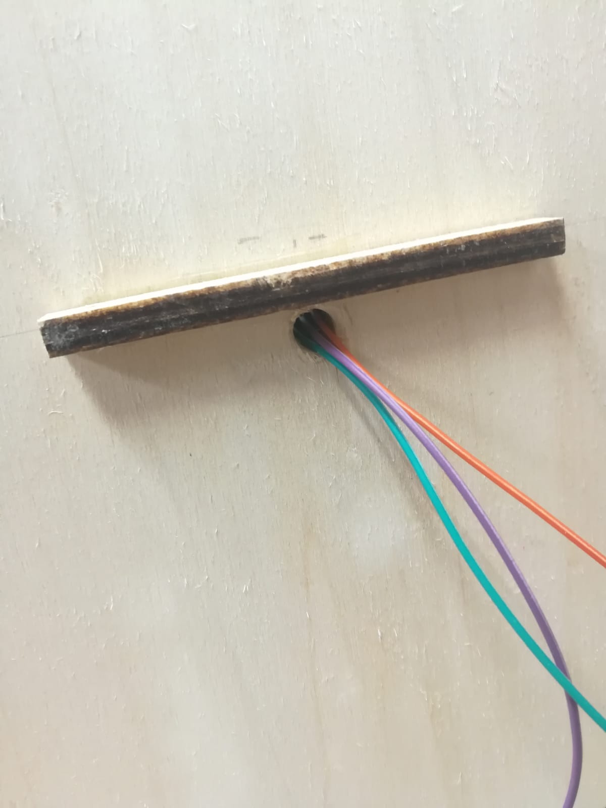
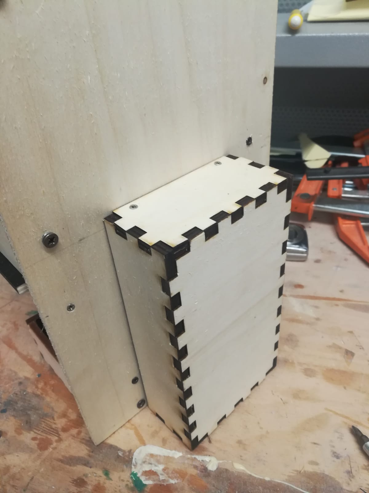
I screwed the boxes and I made a hole with a column drill to allow the sensor wires to pass through and enter in the box. It doesn't matter that the tip is very large because the cables are small.
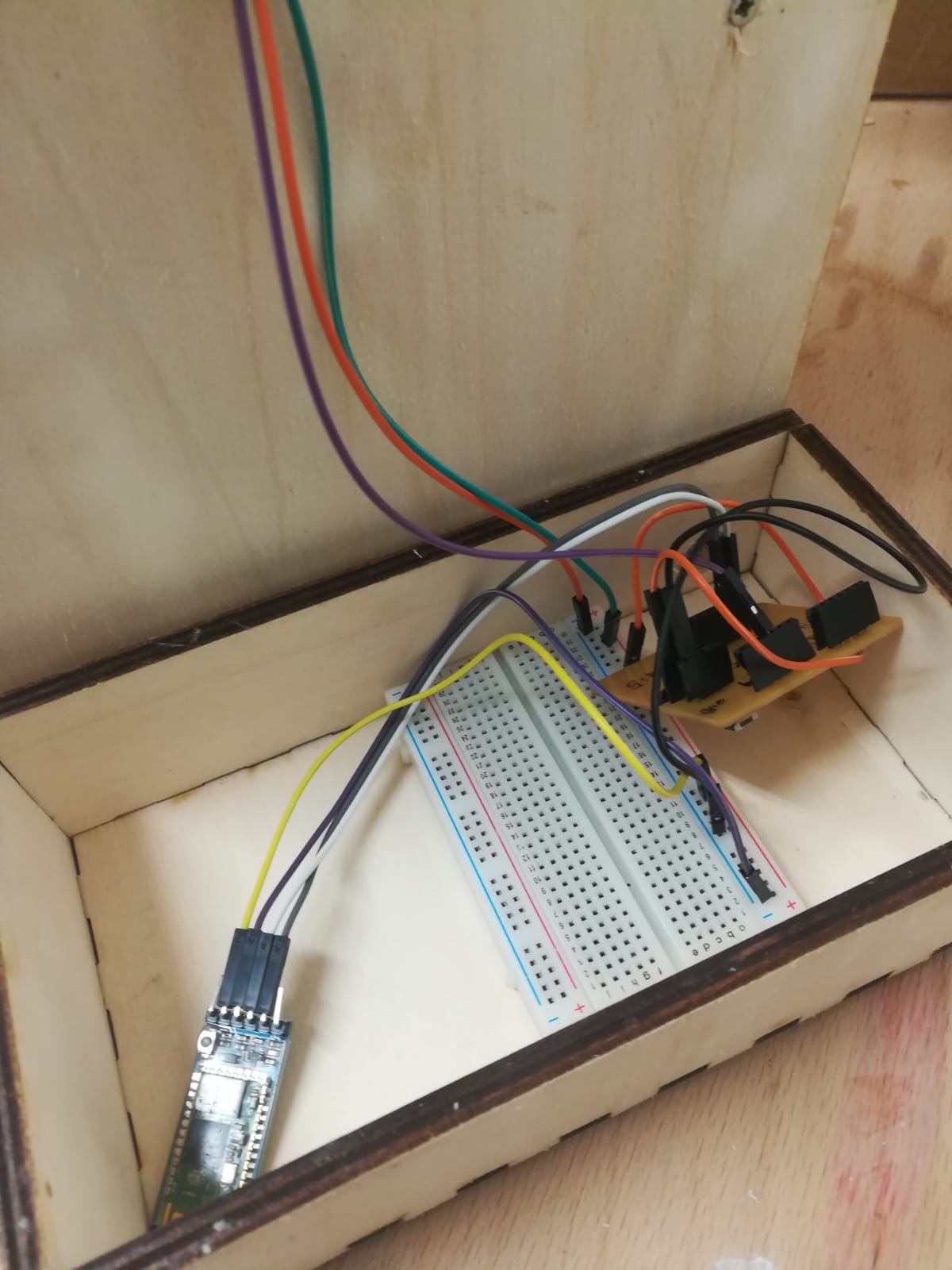
Then I took the measurements of the box that will contain the electronic part and cutted a small piece of wood that I glued in order to create a support where to screw the box.

I inserted the wires with the sensor and screwed the box with electronic components (and already programmed) inside.
 |
 |
This is the end result of the back
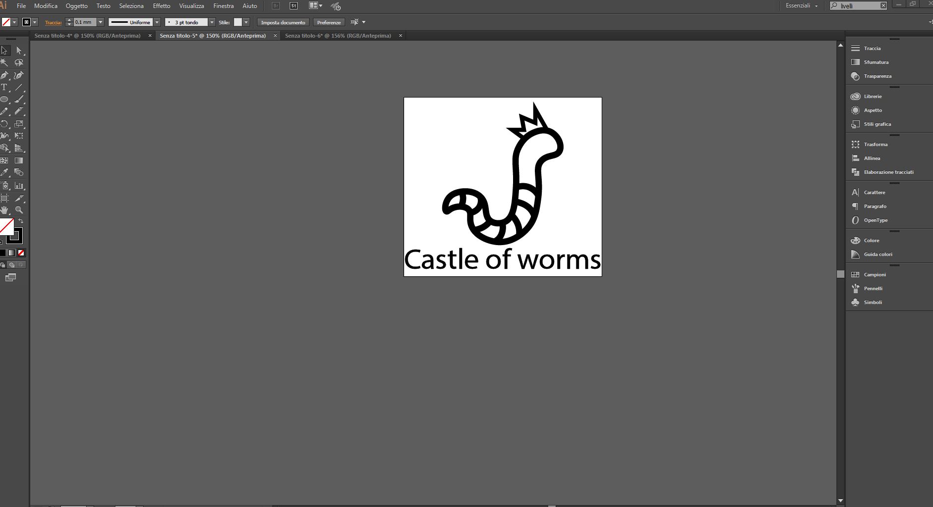
Since the space above the first box is empty I decided to engrave a logo on my device. Initially I searched on internet for a captivating image of a cartoon-style worm and I immediately lasered it but I made a mistake: that image had copyright! Consequently I had to spend a good half hour erasing it with sandpaper. To avoid this kind of problems I personally create my logo with Inkscape.
So this is the end result of the physical part.
Software
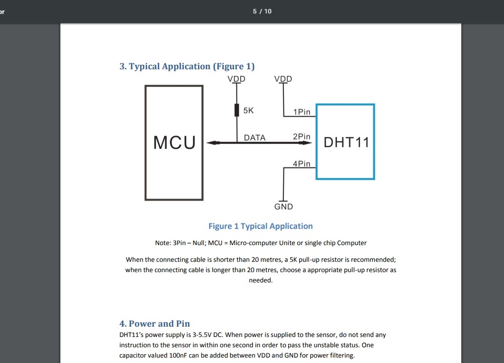
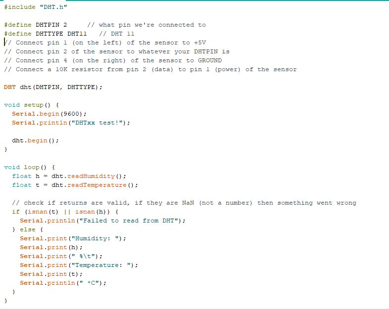
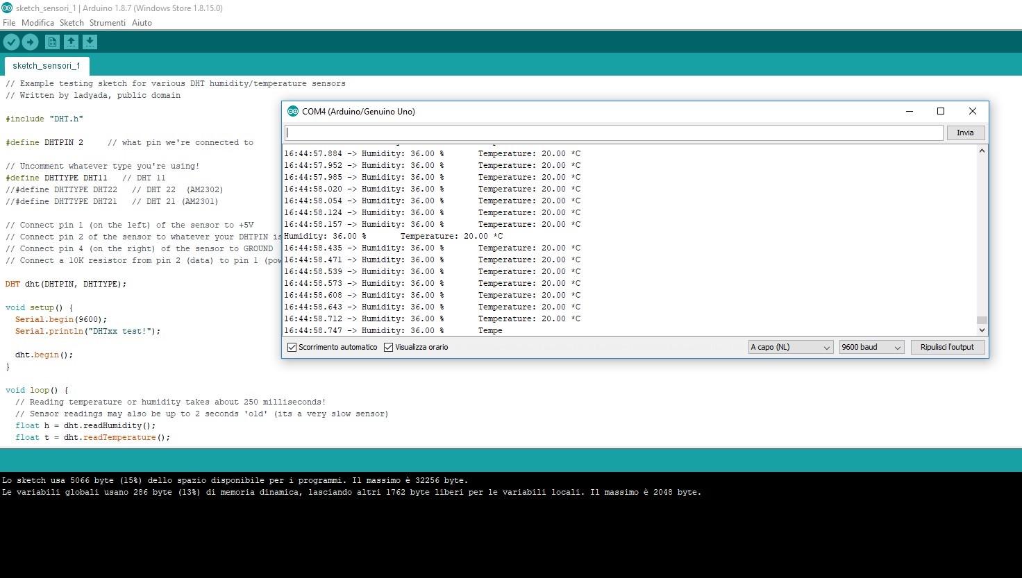
In my project there is a humidity and temperature sensor, DHT11. I wanted to test it to see how it works and understand its features. The sensor has 3 pins: vcc, data and gnd and it works with a supply of 3-5.5V. I connected the data pin to the pin 2 of my arduino genuino uno.
And then I opened the serial monitor. As you can see the sensor works properly
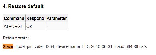
The next step is to read the sensor data via the bluetooth module. first of all it's necessary to set the bluetooth module as slave: connect the module through an FTDI cable and the enable pin to the power supply of 5V, then open the serial monitor on arduino ide and set the AT mode. You can see other way to program the bluetooth module in this page
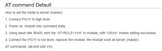 |
This is the first part where is described how to set the module, what pin must be connected and the baud rate. |
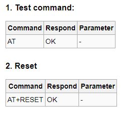 |
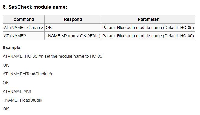
Those are the command to check if the module is connected and to reset the module so you can set the module with the desired function. |
This is the sketch to read the data from the bluetooth module to the pc.
#include#include int pinDHT11 = 2; SimpleDHT11 dht11(pinDHT11); SoftwareSerial btserial(10, 11);//bluetooth pin void setup() { btserial.begin(9600); delay(20); } void loop() { float temperature = 0; float humidity = 0; int err = SimpleDHTErrSuccess; if ((err = dht11.read2(&temperature, &humidity, NULL)) != SimpleDHTErrSuccess) { btserial.print("Read DHT11 failed, err="); btserial.println(err);delay(1000); return; } btserial.print((float)temperature); btserial.print(","); btserial.println((float)humidity); // DHT11 sampling rate is 1.0HZ. delay(1000); }
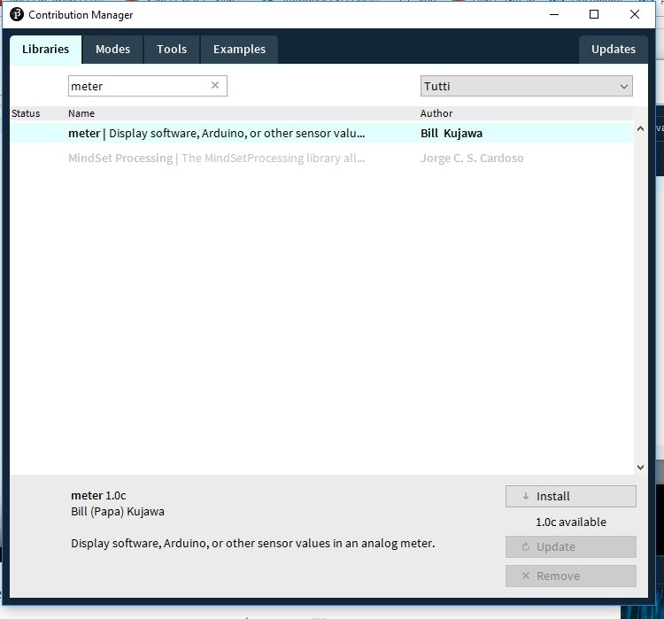
Now it's time to create an interface. My intention is to create an interface that monitors the three drawers based on humidity and temperature. I found this tutorial on how to build a meter on processing, just what is right for me. I modified and customized it to my liking. To make this meter you need a separate library that you find in contribution manager on processing just typing "meter".
After adding the library I started making the meter. Further additions and modifications are possible thanks to the references found on this page
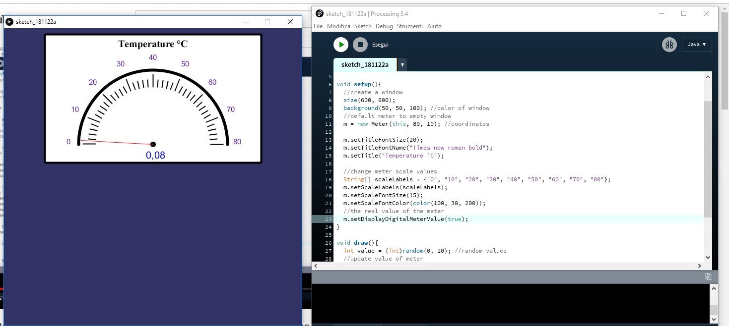
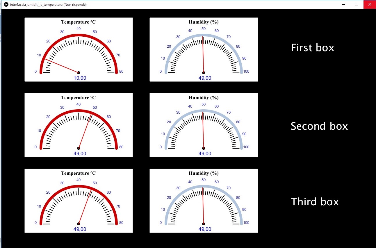
After deciding how to make the meter aesthetically I started to duplicate others and to place them in the window
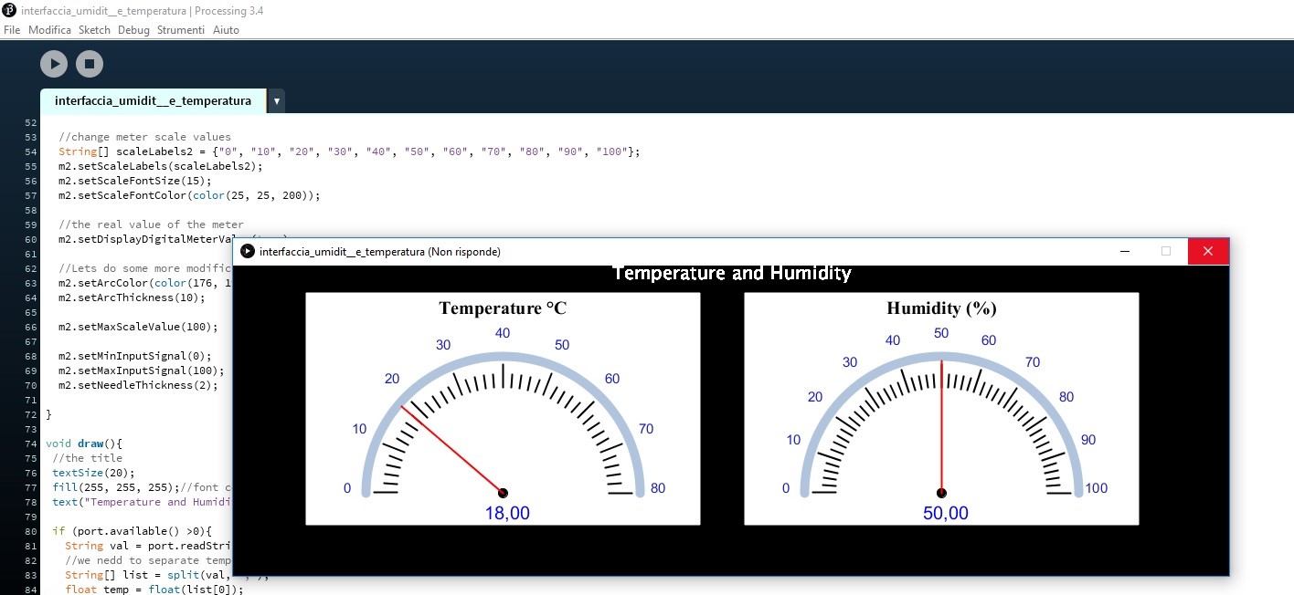
And this is the final interface
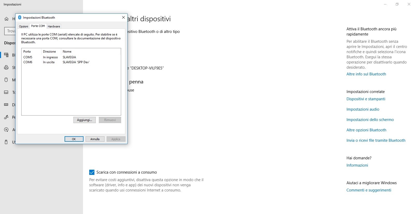
Now it's time to send the data that the bluetooth receives from the sensor to the interface. To do this it is necessary to configure the access port so that the PC reads the input data and not the output, so go to the ->bluetooth settings to see what port is (in this case the COM 5) and when you add the module just select it as input.
Electronics
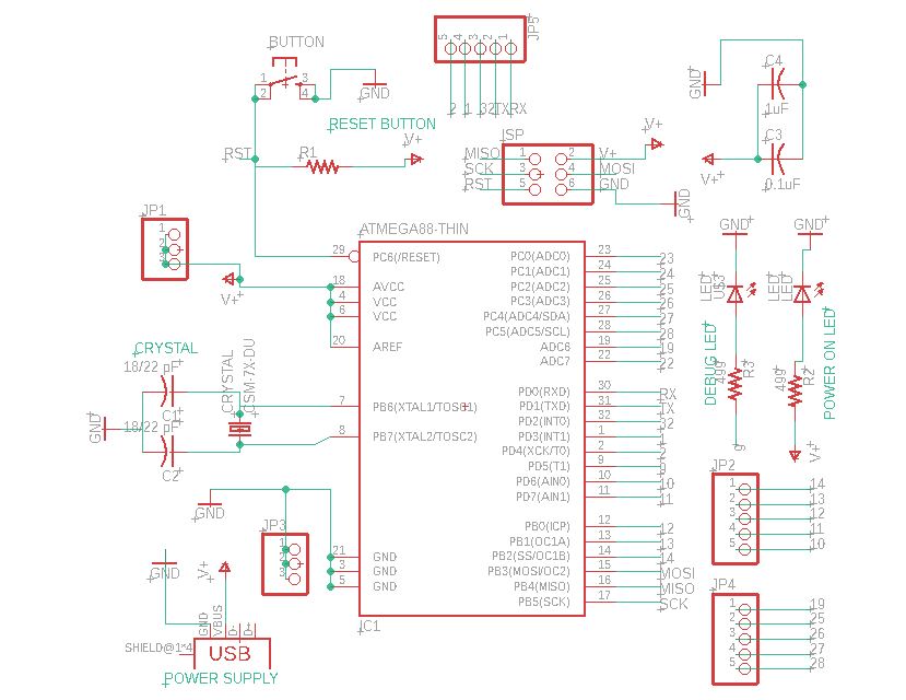
For the electronic component I initially thought of networking among several boards, but having simplified my project I no longer need it, so I opted for a satshakit also to have the possibility of adding future implementations to my device. For the satshakit I looked at the documentation of Dario. Here is the schematic and below the board.
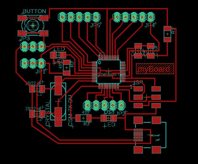
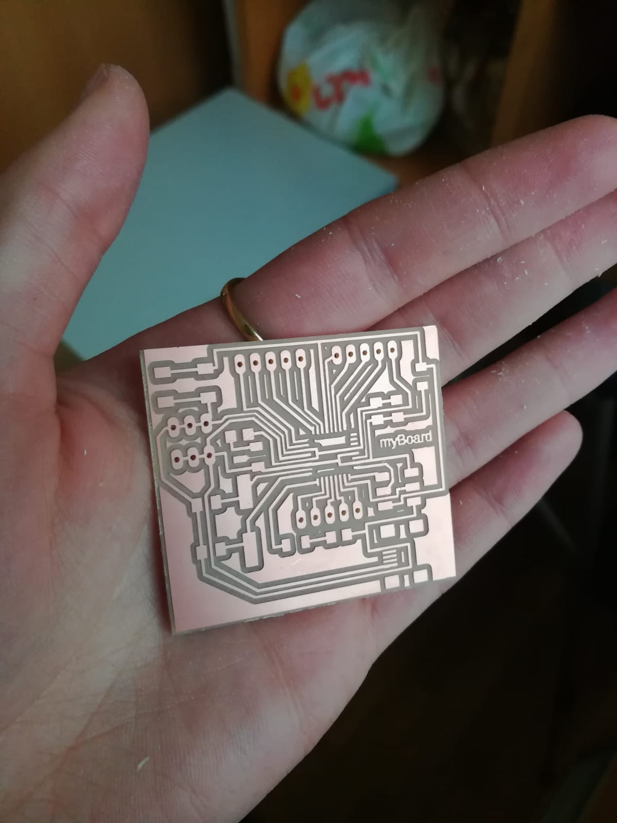
I made the Bom and then I soldered the board.
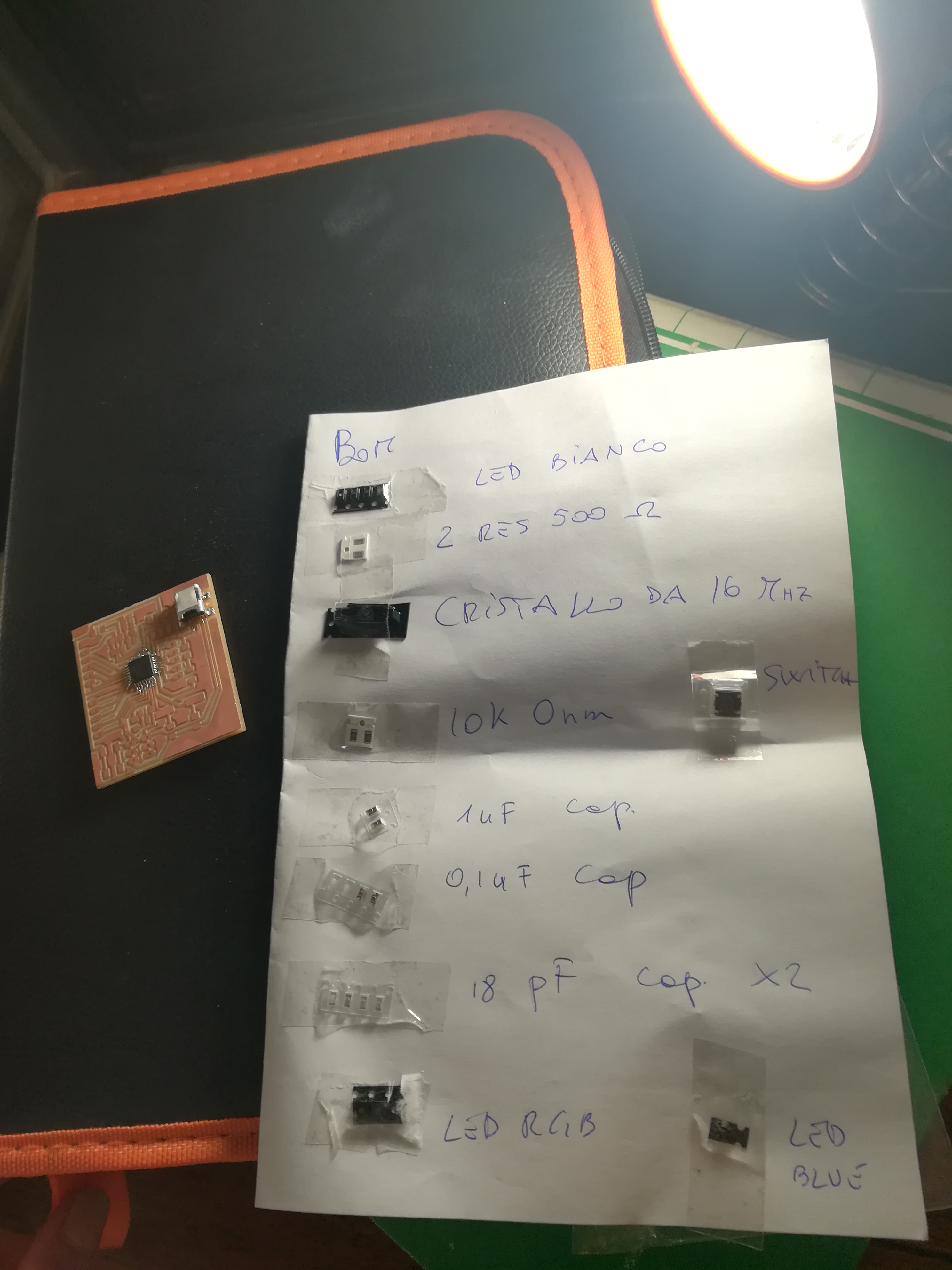 |
BOM
|
I must say that at the beginning the microcontroller worried me a bit with all those many pins close together, but in the end the final result I have to say is satisfactory
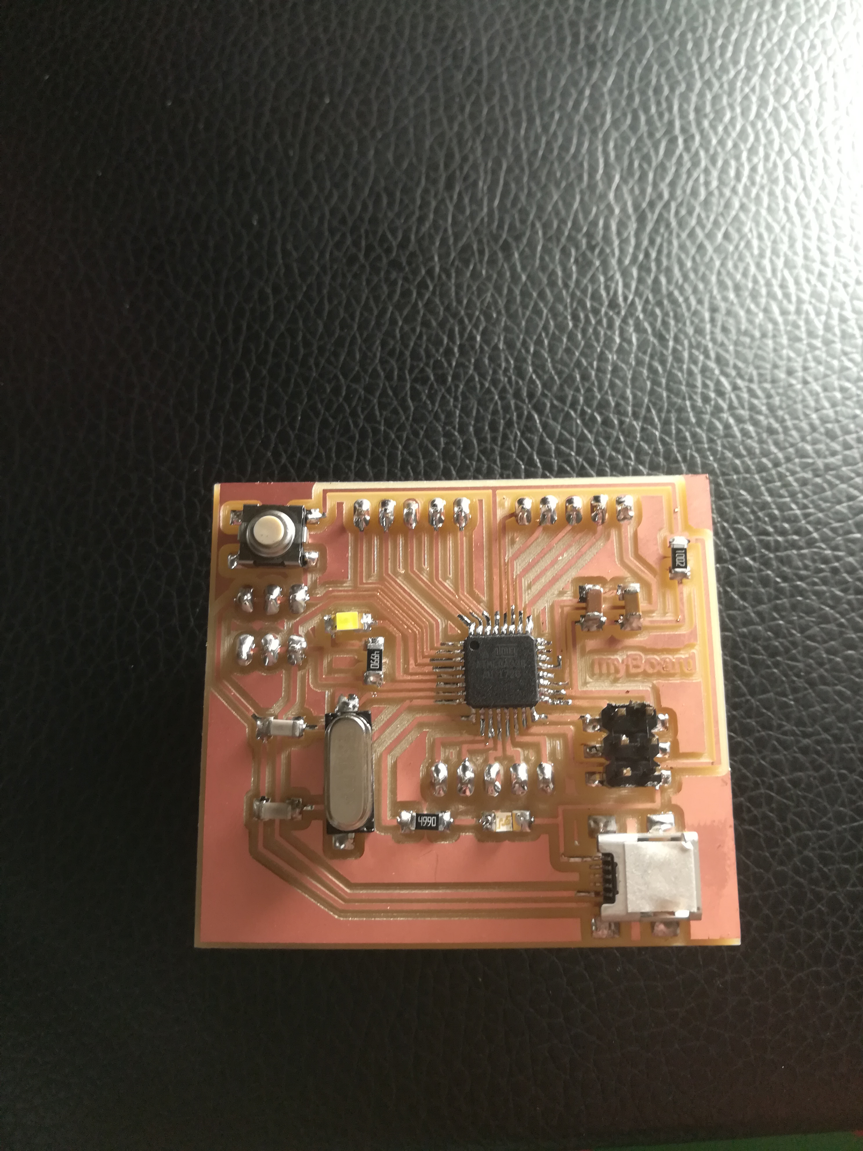
After programming the board I put it in the back box of the final project, which I screwed in to make it stable but also easy to remove. I created a hole to pass the thread.
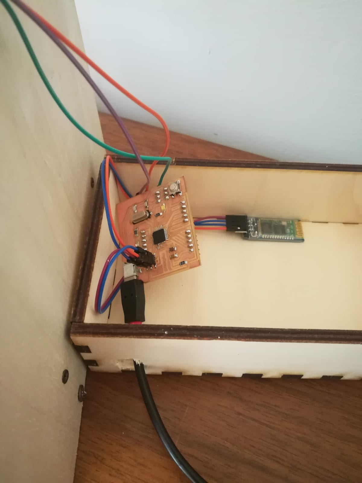
Update 17/06
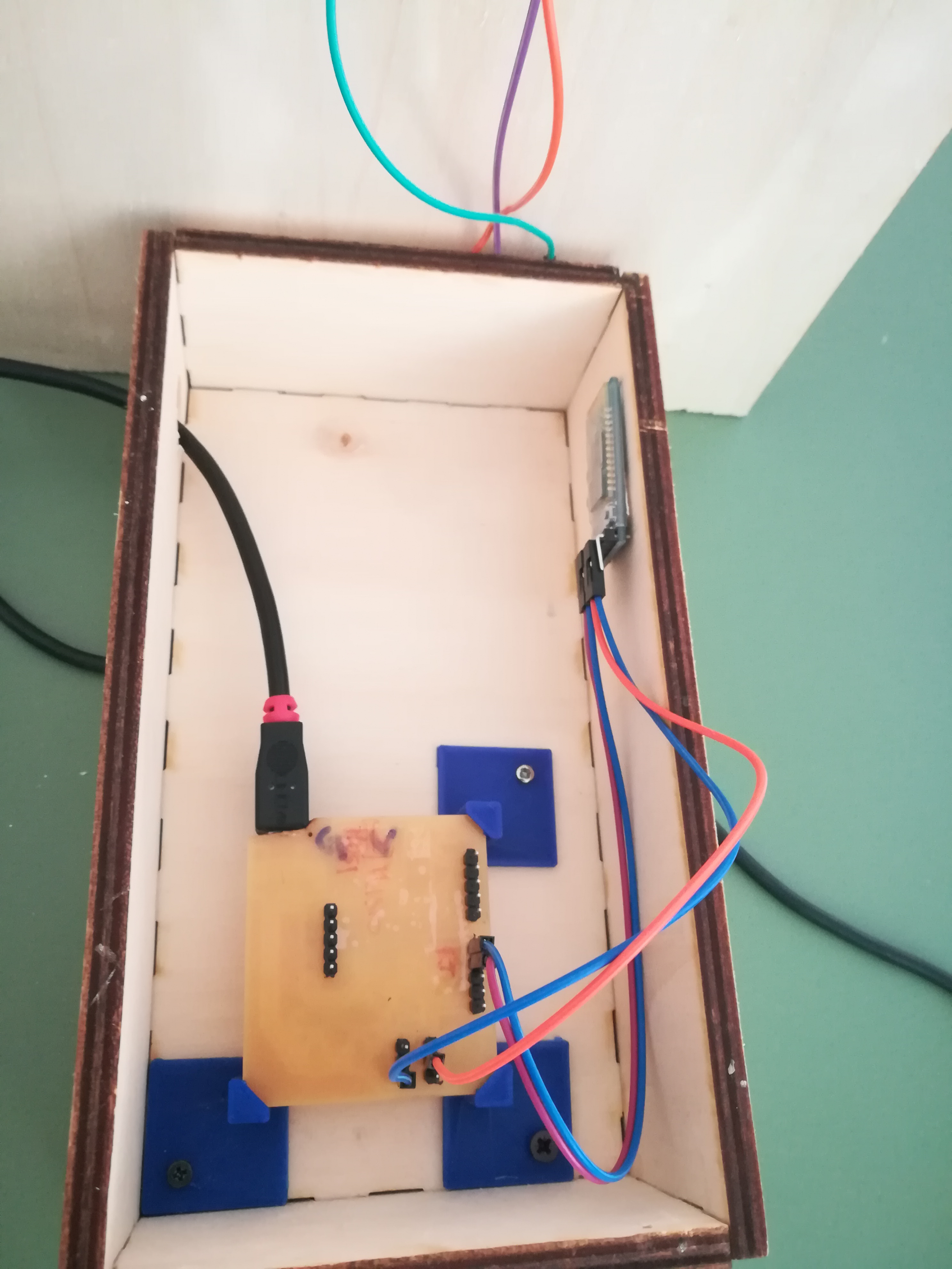
During the presentation Neil pointed out to me that the components were not well fixed to the box and this could damage the wires and the various components, so I made supports for the board in order to protect it. For the bluetooth module I decided to simply glue it with double-sided tape. I must say that the result seems to be optimal.

I made some supports that included the use of screws for future modifications and therefore the possibility to remove the boards
Update 26-06-2018
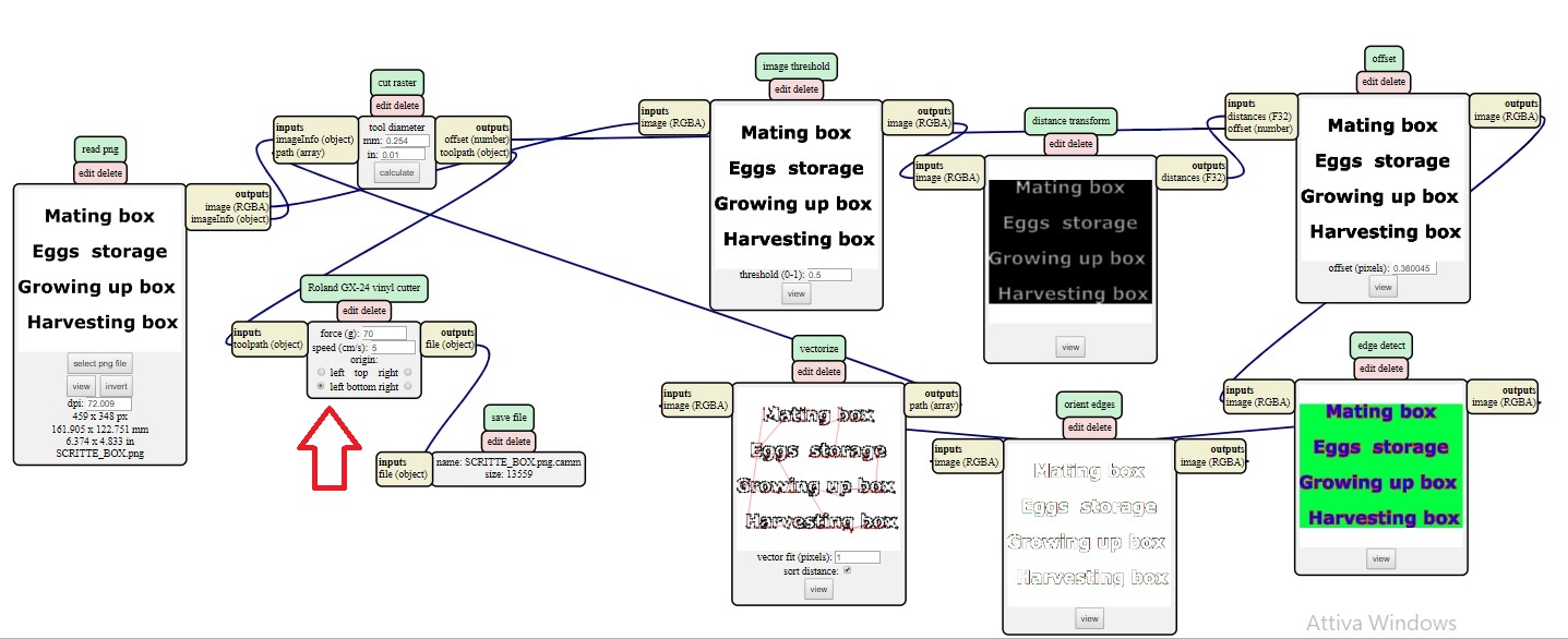
Under suggestion of my global evaluator I decided to add another fabrication technique. I thought of adding the names to the boxes to distinguish the various functions of each part. For this part I used the vinyl cutter. First of all I made the PNG file on Inkscape.

Then I made the .camm file with the fabmodules with the right click of the mouse anywhere on the screen, then programs->open server program->Roland SRM-20->PCB png. The steps are the very similar to those of week 4, only this time the parameters to be changed are these:
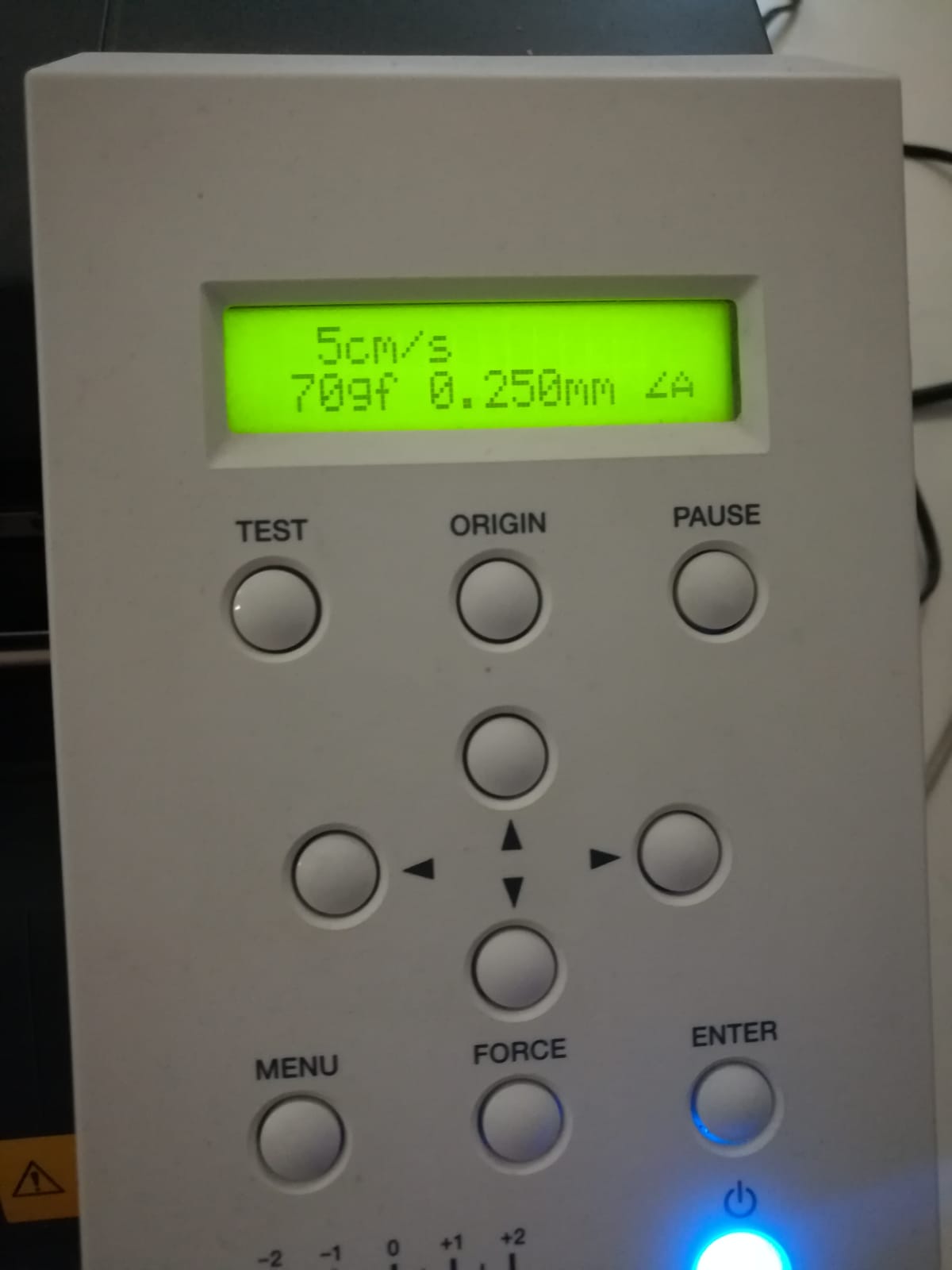
Cutting Force: 70gf
Cutting Speed: 5 cm / sec
After saved the file I transferred it to the PC connected to the vinylcutter, loaded the vinyl sheet and set the parameters from the machine.
I removed the excess vinyl from the writings and put the transfer film on.
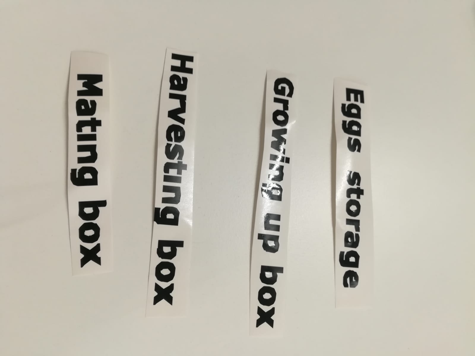
After that I applied the writings on the front of the boxes.
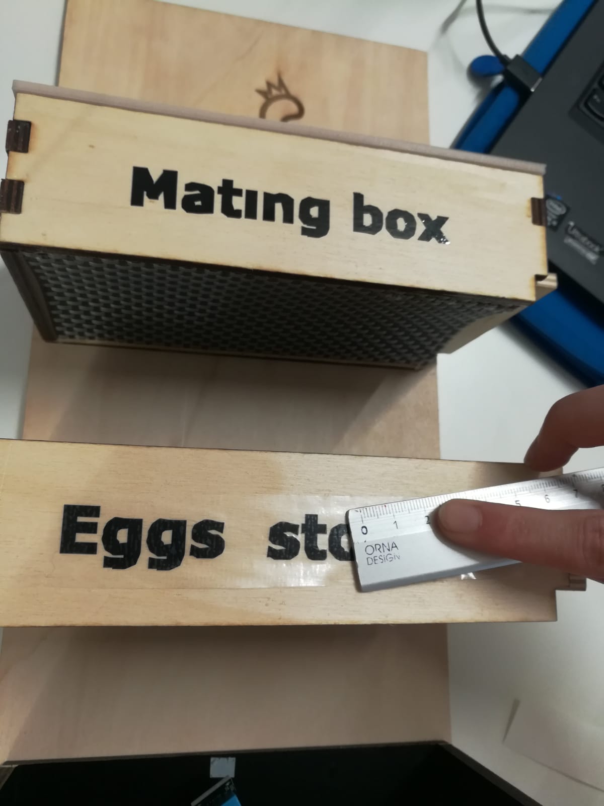
I don't mind the final result, even if the cut came out a little rough it gives an earthy imprint that is inspired by my final project.
Materials and costs
TOTAL: 47 eur |
Download the files