Output Devices
Program an output device to do something
This week's task is explore with output devices. I decided to continue my work with the soil moisture sensor as it's a part of my final project. The output device here is the relay connected to the water pump.
At first, I was planning on programming a water valve. After a couple of days of failed attempts, I was advised by QBIC Fablab staff to try a water pump. So I went and bought myself a water pump that's usually used in fish aquariums. To be able to control the water pump, of course I need to work with a relay. Relays are electrically operated switches. They're ideal for controlling currents where several circuits must be controlled by one signal. To connect the water pump to the relay, I had to cut the wire and connect the common "C" terminal to the power supply, and the Normally Open "NO" terminal to the water pump.

The code for controlling the water pump is:
//Soil Moisture and Relay Sensor
int Relay = 13;
int sensor = A0;
int val;
void setup() {
pinMode(13,OUTPUT); //Set pin 13 as OUTPUT pin, to send signal to relay
pinMode(A0,INPUT); //Set pin A0 as INPUT pin, to receive data from Soil moisture sensor.
Serial.begin(9600);
}
void loop() {
val = analogRead(A0);
Serial.println (val);
if(val < 300)
{
digitalWrite(13,HIGH); //if soil moisture sensor provides LOW value send HIGH value to relay
}
else
{
digitalWrite(13,LOW); //if soil moisture sensor provides HIGH value send LOW value to relay
}
delay(10000);
}
}
This code is specific to the sensor I am using. Other sensors work the other way round, where the lower the value, the more moist the sensor is. In our case, 0 means dry, the larger value reflect an increase in humidity. (You will see more of this when you go through my final project, where I had to use a different sensor).
I verified the code and uploaded it to the arduino board.
I connected my moisture sensor to the board by connecting the negative to GND, positive to 3.3V and signal to A0, and went on the sensor monitor. The relay was connected similarly, negative to GND, positive to 5V and signal to 13.
Testing the circuit:
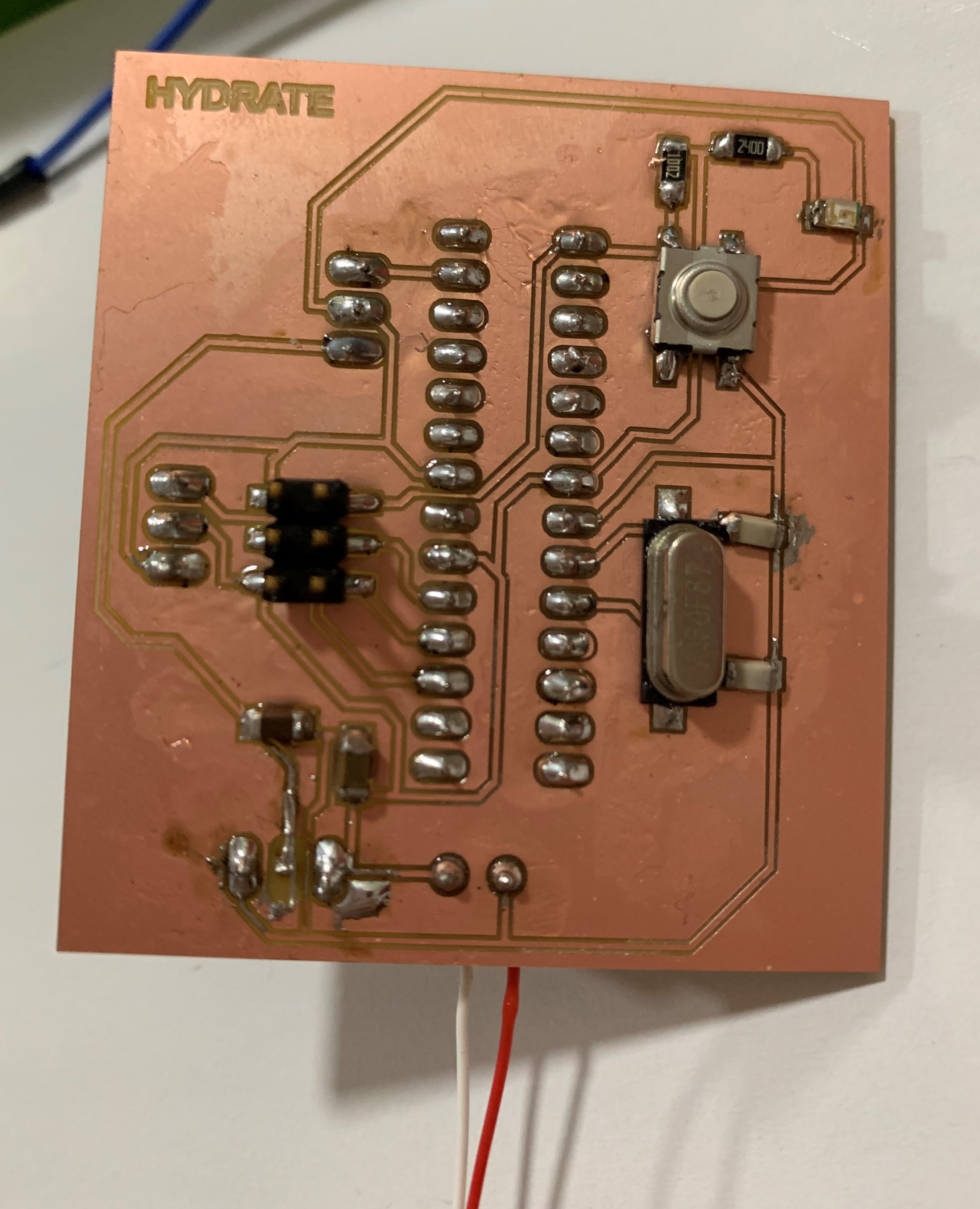
The next step is to use my own board. I designed the board to fit my input and output needs, so I can use it for my final project. You can see the full design process in week 11 .
I first downloaded satshakit to use it as a reference. This is the original board, most of the componenets on which I did not need.

I was going to use an ATMEGA168V, so I used its data sheet to get pin configuration details:

This is the final board:

Then, I removed the programmed ATMEGA168V microcontroller from the Arduino board and insterted it in my fabduino. The decision to use an ATMEGA168V is explained in my final project process.
Then, I removed the programmed ATMEGA168V microcontroller from the Arduino board that I previously programmed and insterted it in my fabduino. The decision to use an ATMEGA168V is explained in my Week 20. documentation.
