Input Devices
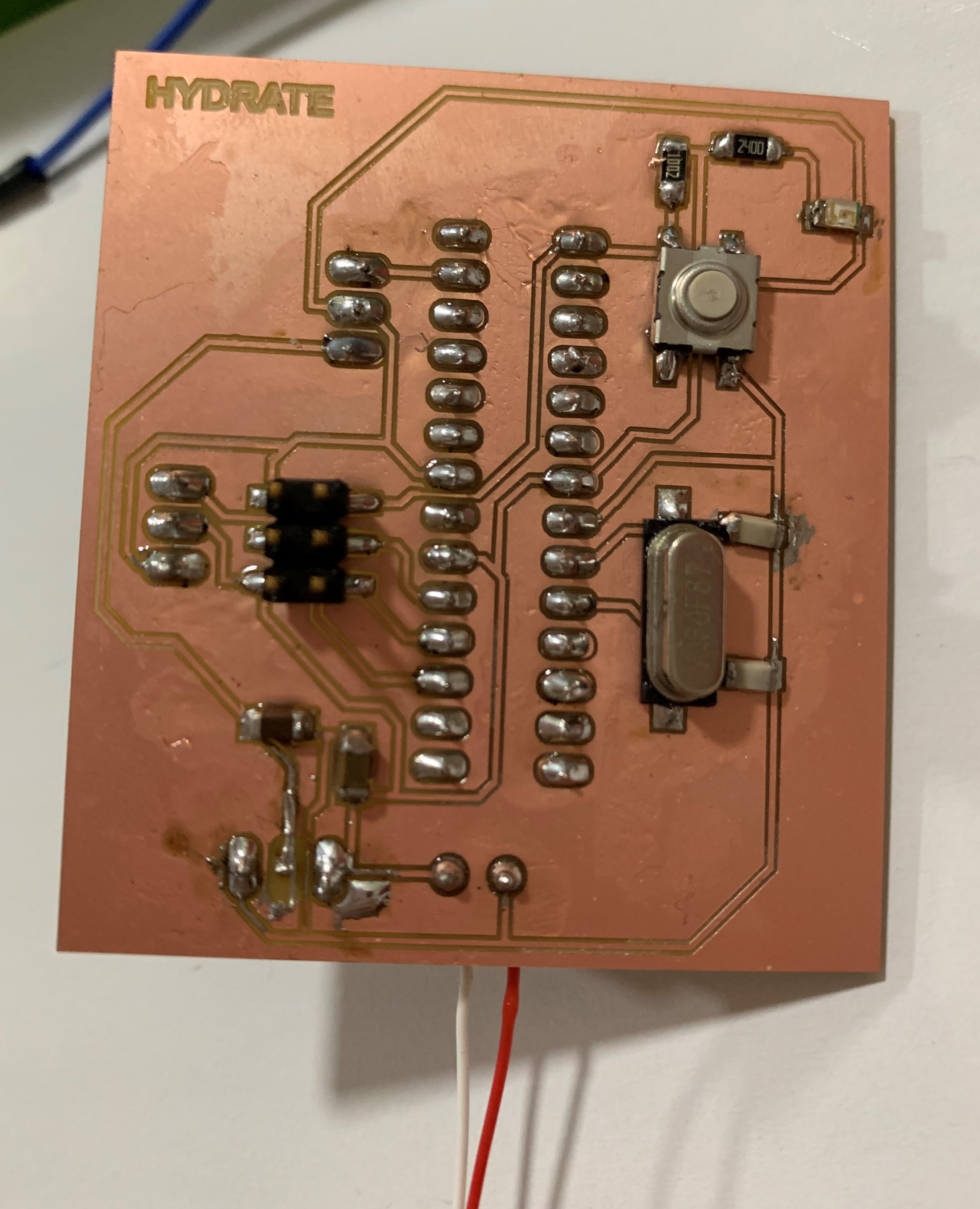
A sensor on a designed microcontroller board.
This week's task is explore with input devices. I decided to work with a soil moisture sensor as it's a part of my final project.

I first attempted it with an Arduino UNO board before making my own board.
First thing I did was connect the Arduion board to the computer using the USB port. On the Arduino software, I included the following code:
/*
# 0 ~300 dry soil
# 300~700 humid soil
# 700~950 in water
*/
void setup(){
Serial.begin(57600);
}
void loop(){
Serial.print("Moisture Sensor Value:");
Serial.println(analogRead(0));
delay(100);
}
I verified the code and uploaded it.

I connected my moisture sensor to the board by connecting the negative to GND, positive to 5V and Signal to A0, and went on the sensor monitor.

This is what I got:

I realized that the delay was very short. So I increased it to 5000 and tried again. The video below shows the movement of the sensor, and the screenshot after shows the results on the monitor.

As you can see, at first I took the sensor from air to the water, and then took it out and dried it out. During the process, you can see the moisture level going from 0 to 533 and then down to 301. This point is important, as it shows me what values represent moisture and what values represent the lack of it. As we can see, 0 is the point where there is no moisture, and as humidity gets higher, the value is higher. The significance of this will come later on when I'm creating the code for the whole system - controlling the output using these values.
The next step is to design my own board. I designed the board to fit my input and output needs, so I can use it for my final project. This board is not specific to my input devices assignment. I first downloaded satshakit to use it as a reference. This is the original board, most of the componenets on which I did not need.

I was going to use an ATMEGA168V, so I used its data sheet to get pin configuration details:

Below is the schematic final board:

I moved to generating the board using the icon highlighted below (or File -> Switch to board).

and I connected the components:

The next step was to export, mill, and solder. I followed the steps I followed in the Electronics Production week. However this time, I had an extra file exported for drills. This is the final board:

Then, I removed the programmed ATMEGA168V microcontroller from the Arduino board and insterted it in my fabduino. The decision to use an ATMEGA168V is explained in my Week 20 / documentation.
