Computer-Controlled Machining: Make Something Big!
Make something big is one of the most exciting weeks of Fab Academy. In this assignment we were asked to design and fabricate a big design using CNC technology. In my lab we have the ShopBot, it is one of the powerful yet dangerous CNC machine. I have used it before for clients job, however, I still feel anxious and nervous whenever I have to use it again.
Preparing the Design
For this assignment I did not want to do something bi only, I wanted to do something extremly BIG. My local instructor told me that I am allowed only to use one sheet of plywood, or MDF. However, I convinced him to le use more for my assignment.
Therefore, I started this assignment by browsing over the internet and pintrest for designs that I can either try to replicate or to use as inspiration, since I really had nothing in mind. I found few designs that really captured my attentions, and I decided to go for one of them.

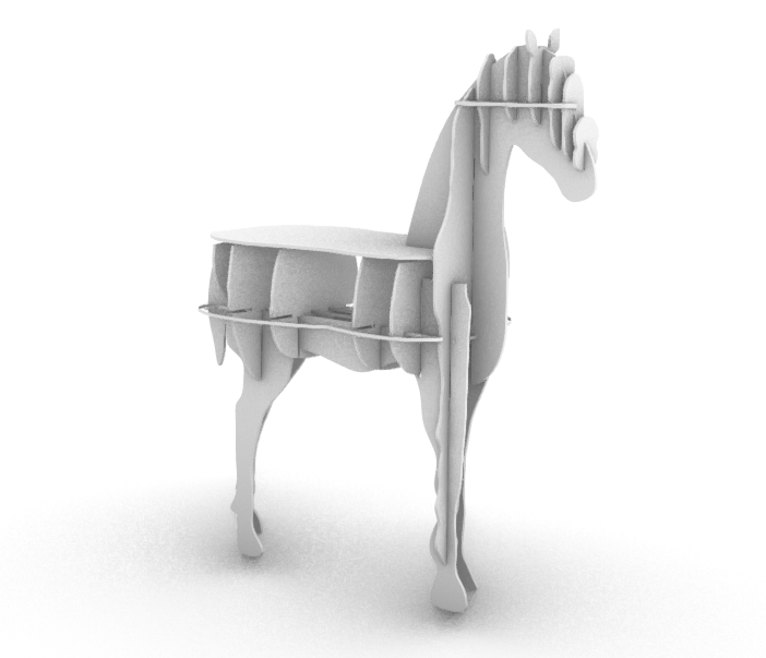
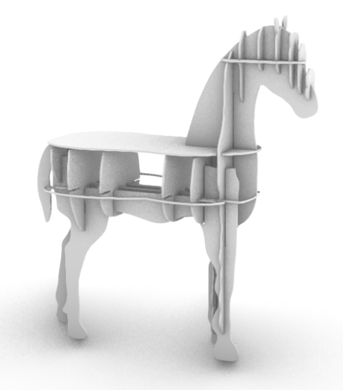
What I like about these designs and what they have all in common that they are a shelves in animal shape (daaa). The first two designs are the one that I really loved. Initillay I had this idea of desiging and fabricating shelvs for the lab to showcase the prototypes we develop. Therefore, when I saw the first two designs I decided to replicate either one of them. The good thing about these designs is that they can be fabricated as showcase of what the CNC is capeable to do and I can use them as to showcase the other prototypes showcase we have.
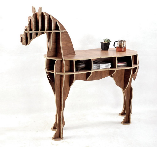
I decided to do the horse design since it is way esier to re-design than the deer. Actually the files for fabricating this designs was available online, however, it was extremly expensive to purchase for the purpose of looking at and modify. Therefore I decided to challenge my self and replicate each piece by just looking at the picture.
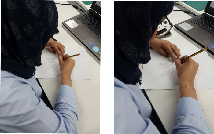
I started designing using old school techniques. I looked at the picture and tried to replicate each piece by drawing it in a paper, to get an approximation of how the pieces look like.
The next stage was taking the design and put it in Rhino and start tracing all the curves I draw in paper.
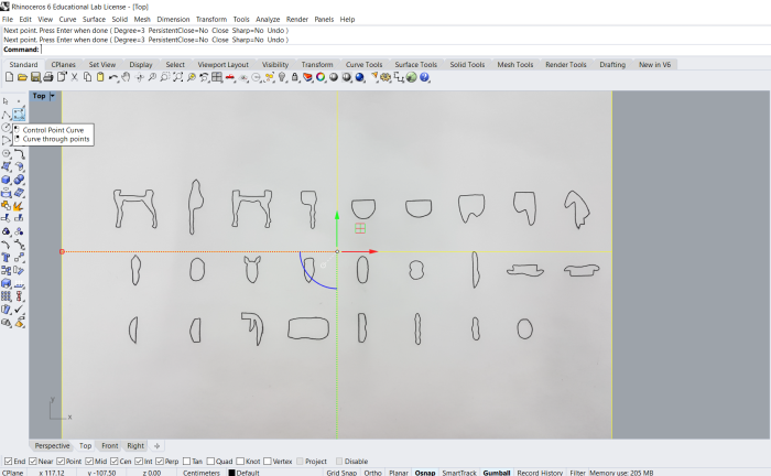
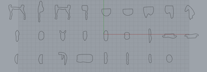
Then and by just looking at the traces I can tell that there is some pieces that requires a little editing; either because of the outer shape or because of the size of the pices. Therefore and using the tools available in Rhino I edited each piece to incorporate the shape of the original model.
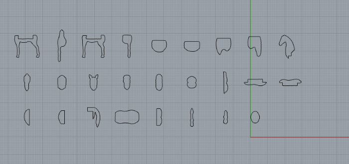
Finally I start creating the junctions of the model. This was actually the tricky and the hardest part of the job, because I had to look at each piece and how it is connected, and make sure that the size and distance between the junctions are perfect and convenient with the other pieces. The MDF and plywood we are going to use are 12 mm thickness, so the size of the junction I did were 11.7 mm, to insure that the pieces will fit together and will be secure enough at the same time. Also I did the bones connections to make sure that when I connect the pieces together they can reach till the end of the juction and not stuck in the middle because of the kerf error the machine's bit caused while cutting.

CNC Fabrication
The machine we have in the lab is ShopBot, which is a CNC tool which is fully 3D capable, as are most CNC routers(this capability is technically described as 3-axis interpolation, which means that moves are made smoothly in 3D space using diagonals and curves). Full 3D CNC involves both designing in 3D and during cutting simultaneous CNC motion in x, y, and z axes.
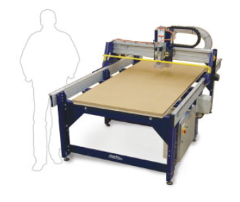
The machine originally comes with two software. One to setup the machine brfore start cutting, and one to setup the file before sending it to the machine. The software that setup the machine called "SopBot 3", this software is going to help you in setting up the x and y orginal of the cut file, and the z axis or orginal of the machine according to the size of the sheet used.
For my case I am going to use 12 mm thickness sheet, of size 2440 by 1200 mm. The first thing to do is to adjust the sheet on the machine bed.
Then, I opened ShopBot 3 to setup my machine before starting the process. There are three main parts in the “ShopBotEasy” panel. Each has specific reason and purpose. The x, y, and z location indicator will show you the live location of the spindle. It will keep on changing while the spindle is moving.
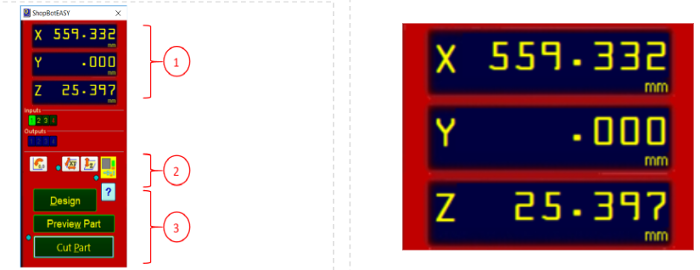
The second part of the easy menu has 4 important icon, the origin point icon, zero x, and y axis, zero z axes, and the keypad. In the keypad panel you can change the location of the spindle, back, front, up, and down across the x, y, and z axes using the arrows shown in the menu.

In this panel you can locate the x, and y origin location of the spindle to where you want it to start the CNC job from. Locate the x, and y origin manually using the arrows then press zero axes from keypad panel. Choose the axes you want to zero then press the ZERO button. And this how you set the cut origins.
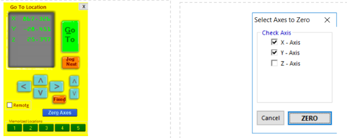
By this you can see from the axes location indicator that the point the spindle is standing in is the zero point for the x, and y axes. To zero the z axes, you need to use both the machine and the software together. In the “ShopBotEasy” panel there is an icon to set the z zero height. Press this icon.
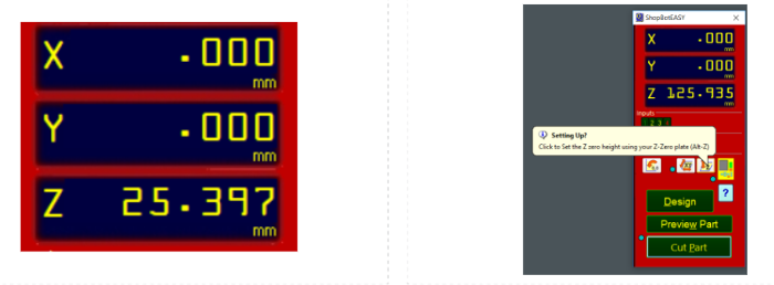
A pop-up message will ask you whether the z plate is ready. For this you need to return back to the machine. In the shopbot you will find this plate together with the clipper. Take it out from its place.
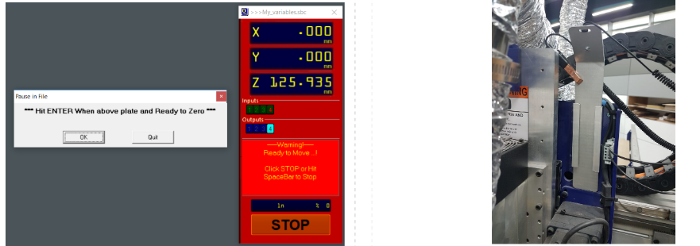
Place the plate under the spindle and exactly under the bit. Take the clip and clip it on the collect nut as it is shown in the above picture.
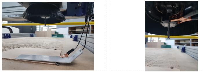
When you are done get back to the pop-up massage and press OK. The spindle will start to move down the z axis until it touches the plate once.
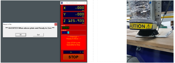
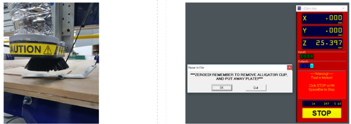
Then slightly moves up, and then it moves down again and touches the plate gently to finalize the location of the z axis. Then finally in the software a massage will pop up identifying that the z axis height has been specified, and remind you to remove the clip and the plate and return it back to their original places.
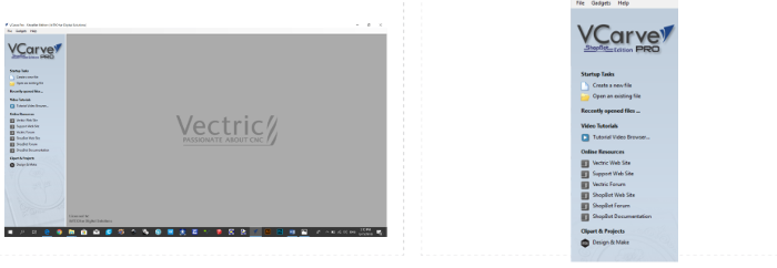
The software used to design or import file to prepare it for CNC cutting or curving is the (VCarve Pro.) To open new file just go directly from small menu in the left of the screen, or you can just go to file- (open, new) in the top far left of the screen.
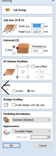
The first thing to do after creating a new file in Vcarve is to insert the diminssions of the sheet I am using for the job. In my case the diminssions was 2440 mm by 1220 mm with 12 mm thickness.
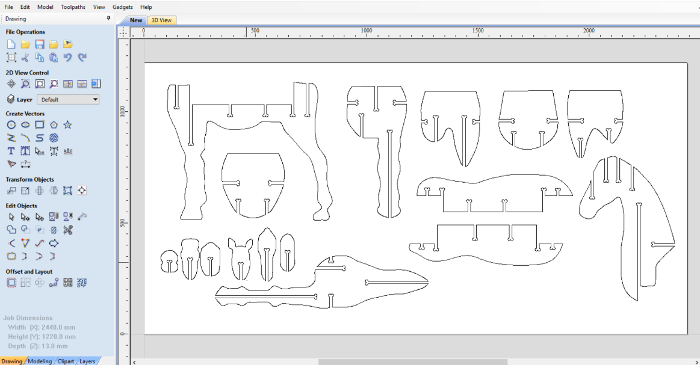
Then I imported my file into the program to start setting it up for the cutting.
For this job we want to perform a cutting order and not an engraving order, therefore the parameters that need to be adjusted are the following:
1. Cutting depth.
2. Number of passed.
3. Machine Vectors.
4. Tabs.
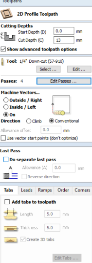
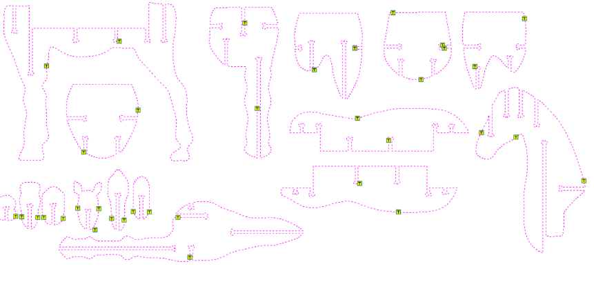
For me I adjusted the cutting depth to be 13 mm just to make sure that the machine will completely reach the end of the inserted sheet. Number of passes is how many pass the machine should take to accomplish the full cut, I adjusted to 4 passes as it is the safest choise. Machine vector is to adjust the machine of the way it behavis when it cut the file. I adjusted to ON option meanning the machine will follow the line exactly. And finally the tabs to make sure the pieces won't move and cause an issue when the machine is cutting the file. The following picture iullstrate the tabs added to the file:
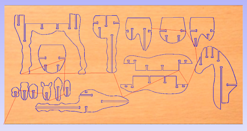
Finally after I finish for setting up my file I ran a simulation to see how the machine will act then I saved the file to upload it in the "ShopBot 3" software to start the cutting process.
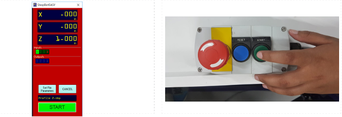
To start the cutting process, go back to ShopBot3 panel and press on “Cut Part” button. A window will pop up, and I selected the file I saved. Note that it is in the “.sbp” format.

After choosing the file, the software and the machine will be ready for starting the cutting job. Press on start button in the ShopBot3 panel. After pressing start from the panel, go to the machine controller and press the start button for the machine to start operating.
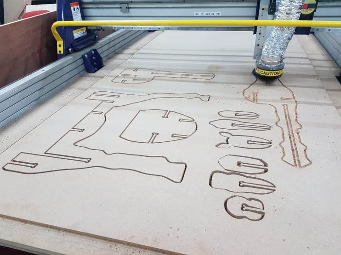
Then finally, the machine will start cutting the file and soon I will get my beloved horse!!
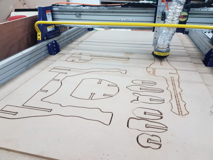
Assembling the Model
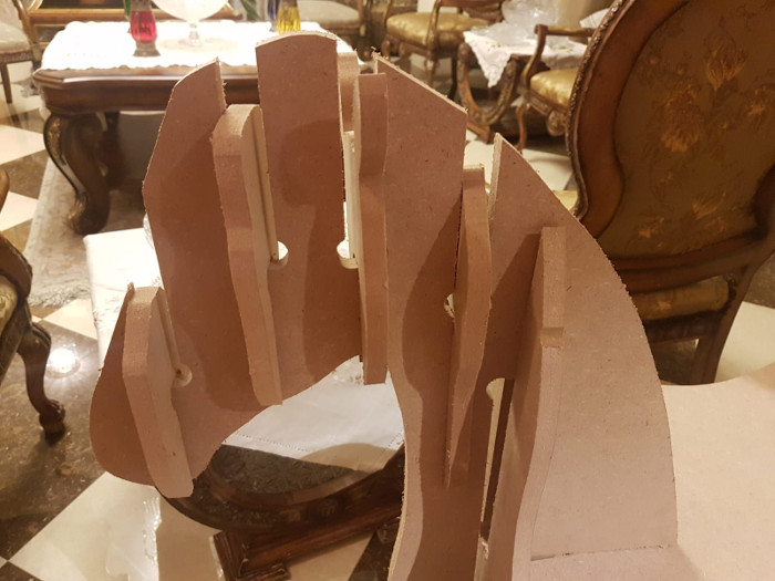
Finally, after a very long process of desiging and fabrication, here is my assebled model
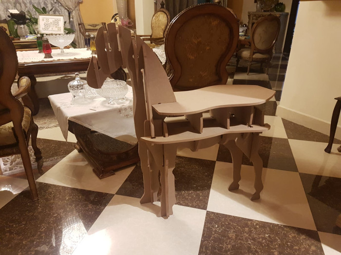
The assembled model was a bit loose, and when I showed to my instructor he told me because I choosed the machine vector to be ON, the measurmentns of the junctions did not come out good. Instead I was suppose to adjust the machine vector to be inside, to get a better results.
