3D Scanning and Printing: Explore every 3D technology
This week of Fab Academy we have been introduced to two of the most powerful tools in digital fabrication which are the 3D printing and 3D scanning. During the global session we were introduced to the different technologies available in 3D printing and scanning, also we got to know the advantages and limitation of each technology.The assignment of this week is to design something that can be only fabricated in the additive technology also known as 3D printing, and to scan an object using the 3D scanner and print it for extra credit.
The Group Assignment
For the group assignment this week we are supposed to test out our 3D printers capabilities in terms of the design constraints. Every 3D printing technology has different capabilities of design restrictions.
When desiging the most important thing to remember is the fact the your design will eveuntually turn into a physical object. Each 3D printing process has its own limitation, to understand fully the process and how you are suppose to design your object you should understand your printer limatations. 3D HUBS website did an amazing summary to explain these design restriction using a table that has all the 3D printing technologies with their design rules.
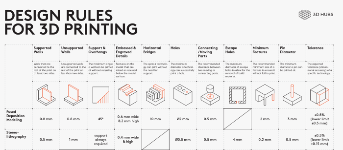
In our lab we have the Ultimaker 2+ 3D printer, which a FDM technology. Therefore and following the above table we have tested some of the design rules of our printer such as; the wall thickness, overhangs print, layer hight, build plate adhesion, and infill density. We use the following template to illustrate the printing setups of Ultimaker 2+.
3D Printing
In 3D printing assignment this week we were asked to design something that can only be fabricated using 3D printing aka additive technology. Therefore, for this assignment I also decided to work on something related to my final project, since my final project has different parts and require long time to fabricate and develop.
Hence I decided to finalize the one part of my project in this assignment and it is the mount that hold the 3D scanner. In Computer-Aided Design I tried to re-design one of the ready made models that are already available in the market just to test my skills in 3D modeling because it was my first time try to 3D model something. The end result for Computer-Aided Design was not that satisfying since I ignored so many factors that might actullay make the design functionable.
For me this model can is quite good for my application, however, it has some cons that I tried to over come but I could not. Therefore, I decided to change the design completely and move to a new design. What I wanted to do is to design something that would securly hold the 3D scanner and at the same time it can be attached anywhere.
To design the piece I used Rhino and you can find the design steps below:
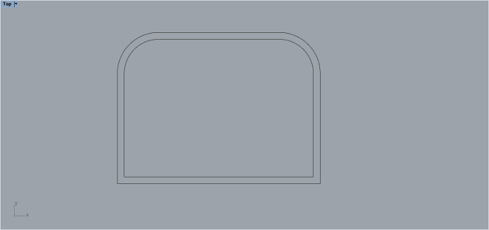
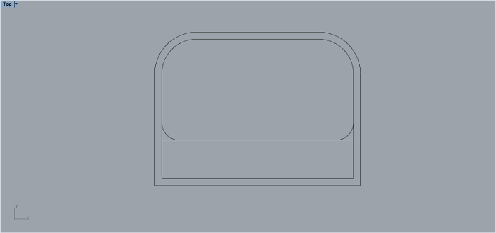
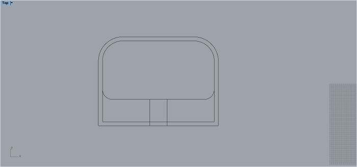
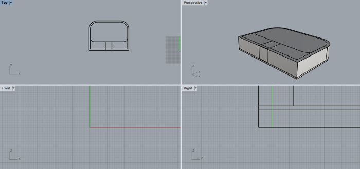
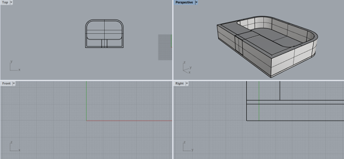
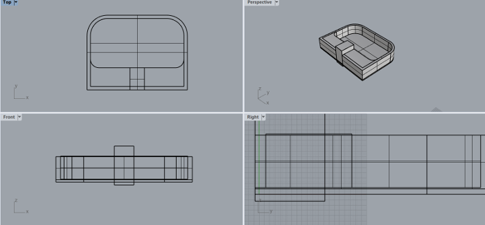
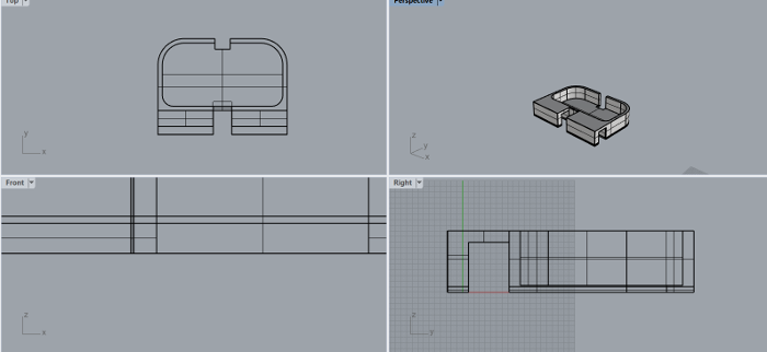
The design I did is not very complicated, it's simple and does the job exactly. Here is the final results of the 3D modeling:
After I finish from the designing process, it is now time to start 3D print the model I designed. For this process I used Ultimaker 2+, which is a powerful 3D printer that uses filament (such as PLA, Nylon, and ABS) to print the object. The idea is basically that we have a solid material (filament), and we are reshaping it to our own 3D model. This is done by melting the filament to become liquid, and then we start to build the model by constructing layer by layer until we get the final shape. The idea is similar to when we build a house, we align bricks layer by layer until we have our own house in its final shape.
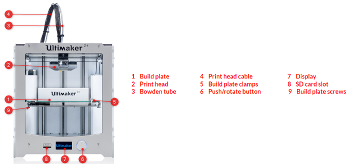
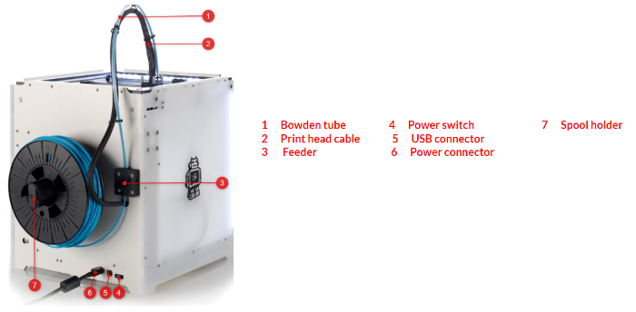
Before 3D printing the model, we should first prepare the printing setups for the designed model using Cura, which is software to prepare your 3D print files. Cura quickly and accurately converts 3D models into 3D print files within seconds, showing you a preview of the print so you can be sure everything is as you would like it to be.
There are few parameters that need to be adjusted before starting the printing process. These parameters are:
1. Type of filament and printer nozzel.
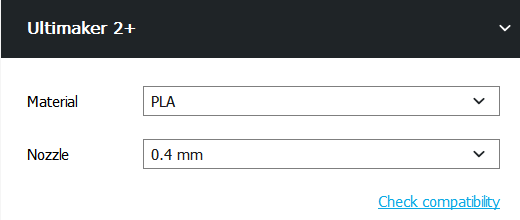
Before start printing it is imprtant to choose the type of filaments you want to use in the 3D printing process. For me I am going to print using PLA so I settled the Material to PLA.
The nozzle is the round spout at the end of the print head used to control the flow of the filament. Usually we Keep the default option (0.4 mm) for the nozzle.
2. Printing quality.

The printing quality is the the steps the printer will travel in the z axis to build the 3D model. The more you increase the step hight the lower resolution the print will turn out, and the faster the print will finish, and vice versa. For me I decided to go with 0.1 mm.
3. Infill density.

The infill section gives you the ability to play with the infill density of your 3D model, the percentage can change to make it less solid or completely filled. I used to infill my 3D model to 20% meanning it won't be completely solid.
4. Printing support.

I enabled the generate support option to support parts of my model which have overhangs. Without these support, such parts would collapse during printing procedure.
5. Build plate adhesion.
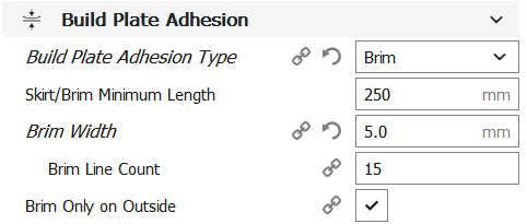
Build plate adhesion type is a different option that help to improve both priming your extrusion and adhesion to the build plate. For my model I choosed to use Brim to adds a single layer flat area around the base of my model to prevent it from warping.
And by this I prepared my model and convert it to G-code which is the formate the printer read to print the 3D model. My print will take around 13 hours and 17 minutes to finish, by the estimation Cura is giving me after adjusting all my printing setups.

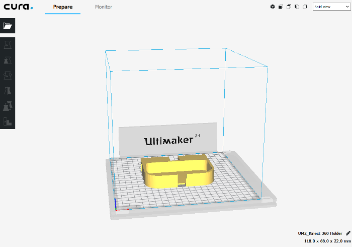
After I was done I took The SD card from the Ultimaker 2+ and saved on it the G-code of my print and then took it to the 3D printer to start printing my model. The printing time took around 18 hours which is 5 more hours than the printer estimated time.
And by this I finished the 3D printing task, and here it is the final results of the 3D printing.
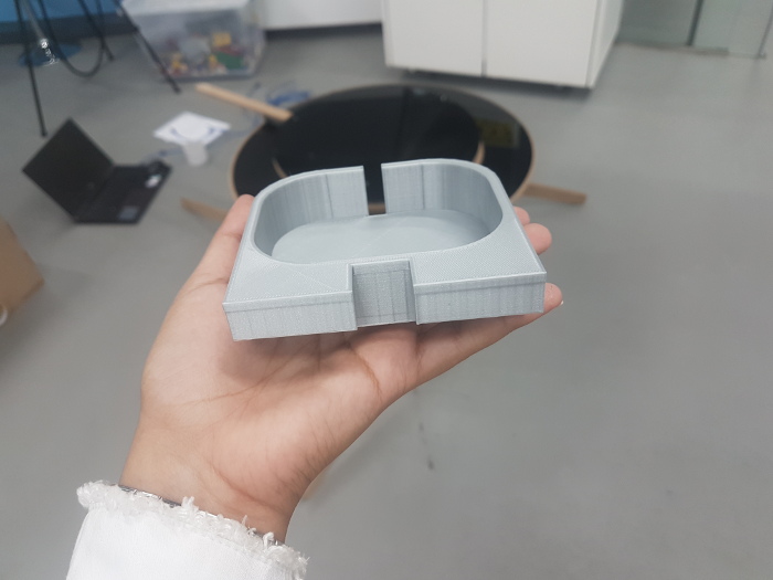
The designed and fabricated model can only be fabricated in Additive Manufacturing because it has a hall faced downward, between to walls that are equal in size, and in order for the subtractive manufacturing technology to fabricate such a design it should be flipped after fabricating it for the first time. Which in results won't work because of alignment issues.
3D Scanning
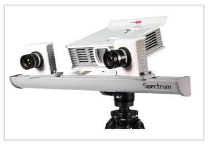
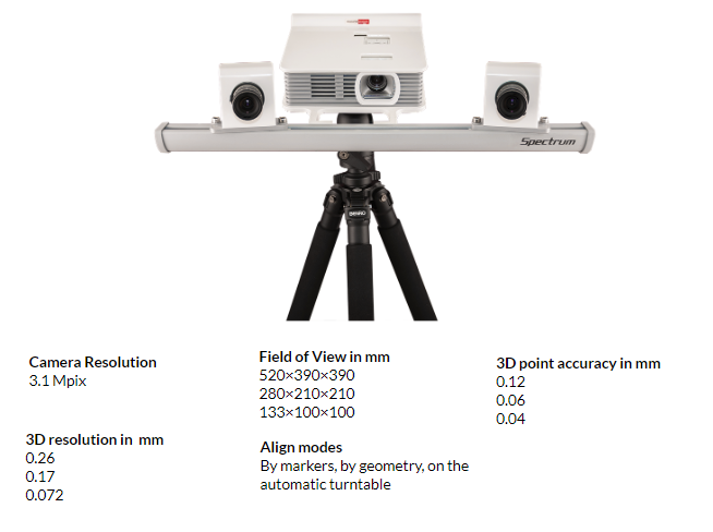
The second part of the assignment is to use the 3D scanning technology to scan an object. In QBIC Fab Lab we have the RangeVision Spectrum 3D scanner which is a high resolution 3D scanner based on the safe-to-use structured light technology. It is designed for scanning small, medium, and larger objects. The 3D scanner has three fields of view and is equipped with 3.1 Mpix industrial color cameras. RangeVision Spectrum captures complex geometry, flat and long objects, as well as small details with constantly high 3D resolution while keeping the accuracy up to 0.04 mm.
The following is the technical specifications of the RangeVision Spectrum 3D scanner:
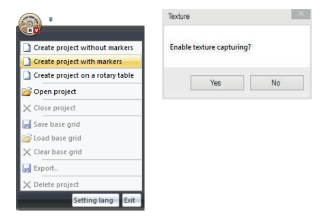
Having said that I started the process by opeining the RangeVision ScanCenter software which is where I going to start the scanning process. I choosed the scanning on a rotary table and I enabled the texture capturing option.
When using a rotary table or a turn table the first thing need to be done is the turntable calibration. To do that I used the small calibration filed provided with the 3D scanner, place it on the table, and choosed the calibration by field option to calibrate the turntable. The calibration will help in automatically adjusting the required brightness of the 3D scanner, and will measure the distance between the turntable and the 3D scanner, which will help eventually in better scanning results.
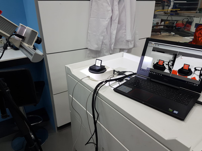
After I finished from the calibration I started the scanning process. I placed my object on the rotary table and I cliecked on the play button to start scanning. What is good about scanning with rotary table is that the 3D scanner collects the required scans in group of meshes and then align them automatically together by spotting the overlaping points. This option minimize the after scanning process, and sometimes results in a better scanning outcomes.
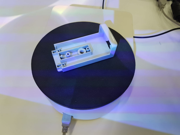
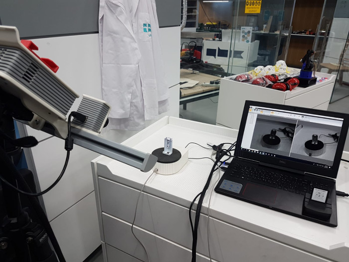
What does the software do is that it divide each scanning orders in group of meshes. each mesh has one angle capture from the rotarty table, therefore, each group has aligned scans of the 3D scanned object. The number of angles is specified by the user, so for me for 360 degree rotation I decided to capture the object 12 times (12 different angles) to insure at least 40% overlapping from one scan and another. Also, another thing that would help in the 3D scanning process is the orientation of the object in the rotary table. So for example I changed the orientation of the object two times (two groups of scans) to insure that the sanner captured the object from all sides and positions.
Moving on after I finish from collecting the requires scans I moved to ScanMerge which is another software for RangeVision 3D scanner to do the after process for the 3D scans.
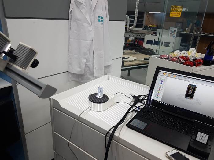
The main purpose of ScanMerge is to initially align all the scans together when using other scanning techniques, to clean the collected scans from any noises, and then finally to build or generate the CAD file. For my scans they have been already aligned together, the only thing left to do for me was to clean them from noises and to generate the CAD file.
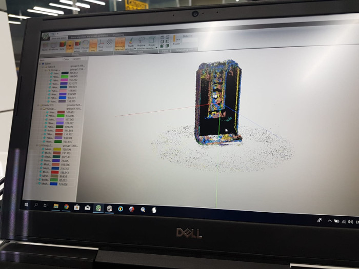
Unfourtunatly, I could not generate the CAD file, since the software kept on crashing whenever I attempted to generate the CAD files. I tried it several times with no luck, and when I read about this issue, there were two reasons either; one is that I don't have enough space in my RAM, or two which is that the laptop I am using is not powerful enough to run this kind of process so it it crushes. Since the laptop I was using was only dedicated for the 3D scanner the second option actully was the reason, and if I want to generate the 3D file for the scans I should change the laptop I am using.