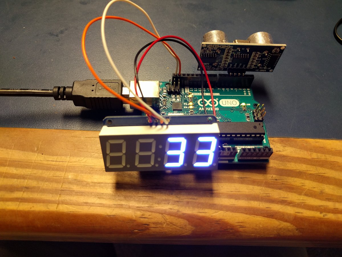
Output Devices: Display data!
In this week we are going to do something different from last week, instead of colloecting data, we are going to display data. An output device is any peripheral that receives data from a sensor or microcontroller, usually for display, projection, or physical movement.
To imagine it well, consider the image shows an inkjet printer, an output device that can make a hard copy of any information shown on your monitor or computer, is a life real example of an output device. Monitors and printers are two of the most common output devices used with a computer.
For my output device I am going to work on something related to my project. My final project is basically a 3D scanning set that has a rotating arm that moves automatically.. I am going to use a stepper motor to rotate the arm around the scanned object.
Schematic Design
Before working with stepper motor it is important to understand how it works and how to operate it. A stepper motor is a brushless, synchronous electric motor that converts digital pulses into mechanical shaft rotation. Its normal shaft motion consists of discrete angular movements of essentially uniform magnitude when driven from sequentially switched DC power supply.
Every revolution of the stepper motor is divided into a discrete number of steps, in many cases 200 steps, and the motor must be sent a separate pulse for each step. The stepper motor can only take one step at a time and each step is the same size.
To control stepper motor with arduino or any microcontroller we should first connect it to a motor driver. The micro-controller has it’s operating voltage limit, say 3.3V or 5V and many stepper motors works at higher voltages than that, therefore, it is important to have a driver to control switching of stepper motor voltages.
Driver is nothing but a circuit arranged to make switching simple and “secure”. The voltage rating of stepper driver is more than micro-controller. So you can easily control the stepper motor of given voltage rating using driver of that rating
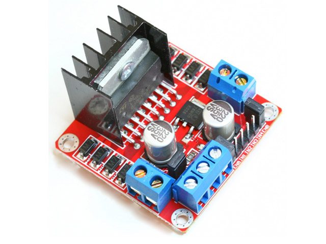
As driver I am going to use the L298N module. This driver has two H-Bridges, each H-Bridge will drive one of the electromagnetic coils of a stepper motor. By energizing these electromagnetic coils in a specific sequence, the shaft of a stepper can be moved forward or backward precisely in small steps. However, the speed of a motor is determined by the how frequently these coils are energized.
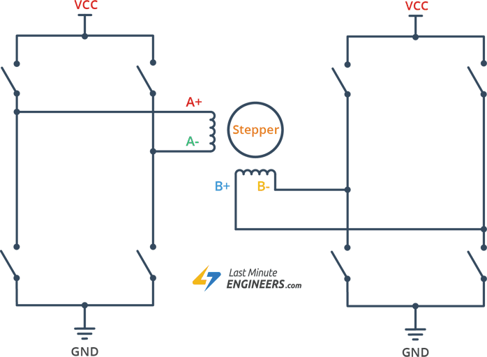
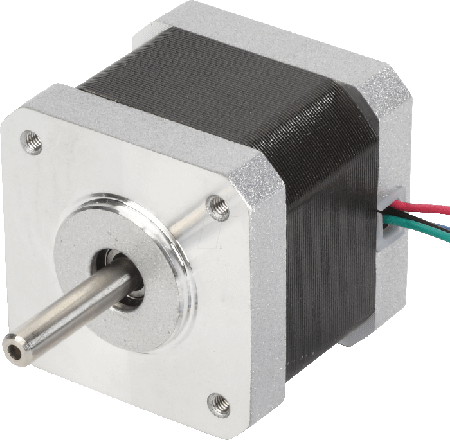
The stepper motor I am using is NEMA 17 bipolar stepper rated at 12V. It offers 200 steps per revolution, and can operate at at 60 RPM. Before start hooking the motor up with the module, it is important to determine the A+, A-, B+ and B- wires on the motor. The best way to do this is to check the datasheet of the motor, or check the color code used with the motor.
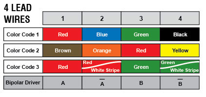
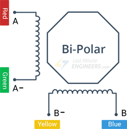
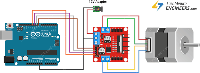
The connections of the stepper motor to the driver and arduino is simple, first I connected external 12V power supply to the VCC terminal. It is also very important to keep both the ENA & ENB jumpers in place so the the motor is always enabled. Then connect the input pins(IN1, IN2, IN3 and IN4) of the L298N module to four Arduino digital output pins(e.g. 8, 9, 10 and 11). Finally, connect the A+, A-, B+ and B- wires from the stepper motor to the module as shown in the illustration below.

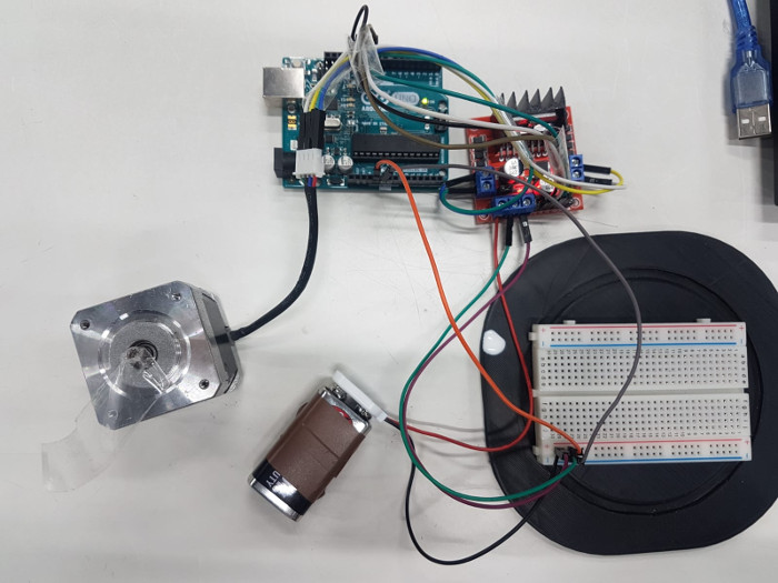
It is very important to me to try these connections first using comercial arduino, to make sure everything is working before moving to designing the PCB.
The code to operate the stepper motor is very easy the only thing require before uploading the code into the arduino is to install the the library of the stepper motor. The following code is to operate the stepper motor in 200 steps, with 60 RPM speed.
// Include the Arduino Stepper Library
#include <Stepper.h>

// Number of steps per output rotation
const int stepsPerRevolution = 200;

// Create Instance of Stepper library
Stepper myStepper(stepsPerRevolution, 8, 9, 10, 11);


void setup()
{
	// set the speed at 60 rpm:
	myStepper.setSpeed(60);
	// initialize the serial port:
	Serial.begin(9600);
}

void loop()
{
	// step one revolution in one direction:
	Serial.println("clockwise");
	myStepper.step(stepsPerRevolution);
	delay(500);

	// step one revolution in the other direction:
	Serial.println("counterclockwise");
	myStepper.step(-stepsPerRevolution);
	delay(500);
}
The following video shows how the stepper motor is working with comercial arduino.
After making sure that everything is working perfectly with comercial arduino, it is now time to design a PCB for my circuit. The microcontroller I am going to use for my cicuit is the Amega328-P, that has the following schematic:
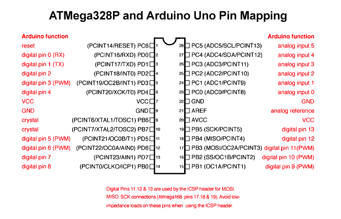
For this assignment I had the schematic almost ready from the previous assignment "Input Devices". However, I just need to edit few pins and remove other to obtain the required PCB.
The previous schematic had the following:
1. Crystal oscilator circuit with two 22pF Capacitor.
2. Switch connected to the Reset with pull up resistor.
3. Programming pins.
4. Joystick pins that has two analog pins.
5. Power pins.
6. NRF24L01 module pins.
7. Voltage regulator to convert 9V to 5V.
8. Voltage regulator to convert 5V to 3.3V.
9. LED connected to power pin.
Things I am going to remove for this schematic is the Joystick pins connections and I am going to replace them with the stepper motor connection. The final schematic will look like the following:
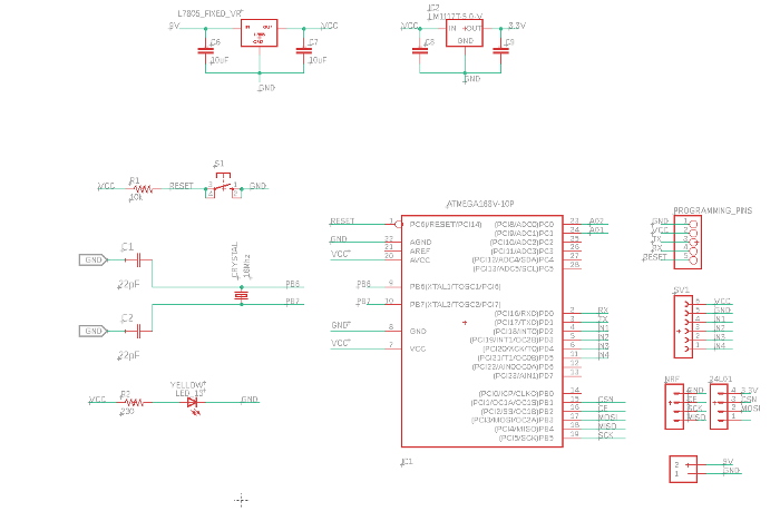
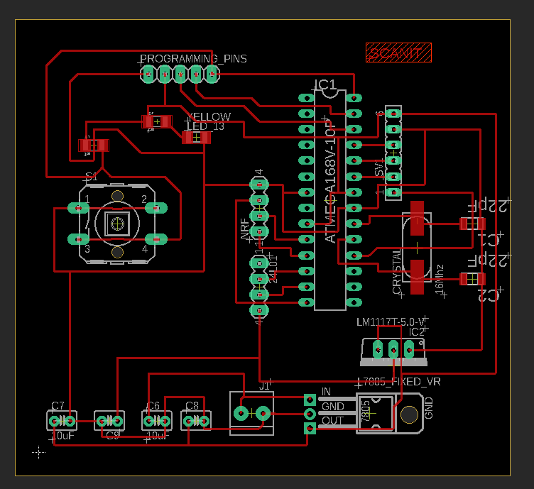
Finally I was able to finish the routing of the circuit, and the final results looked like the following:
Circuit Fabrication
Before Fabricating the circuit, we should first put it in FabModules to prepare the files for the milling process. With that being said, I first prepared the traces milling file as shown below:

The drilling file:
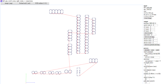
And finally the outline file:
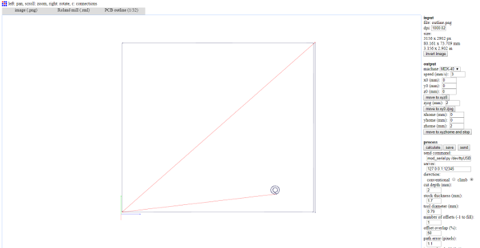
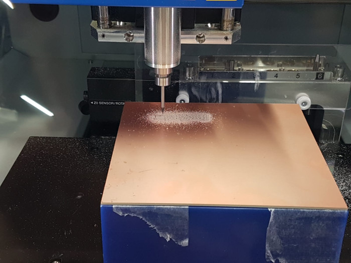
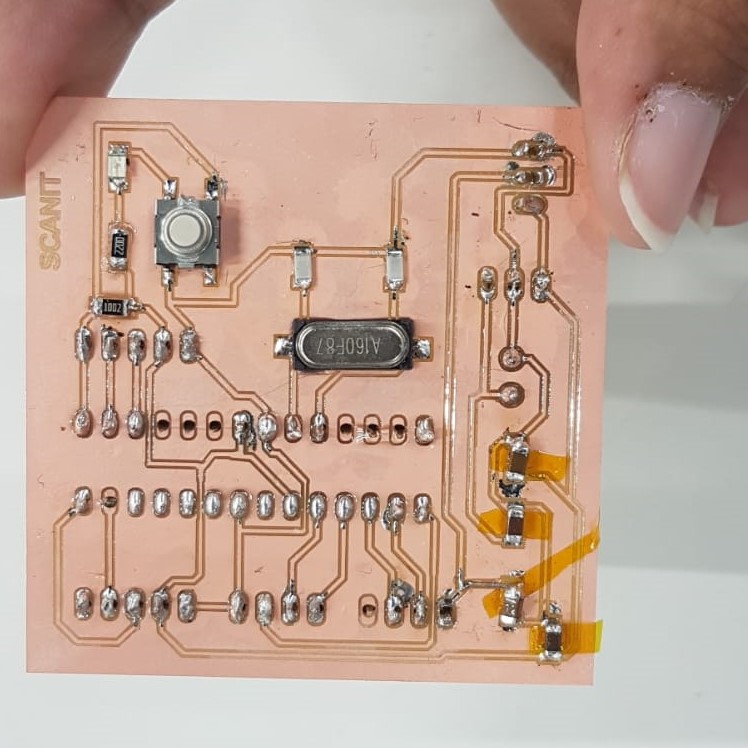
Then I uploaded the files obtained into my machine to start the fabrication process. The process took around hour and half, which was suprising since usually the fabrication require less time, but maybe this happened because I changed the tool I was using for the fabrication.
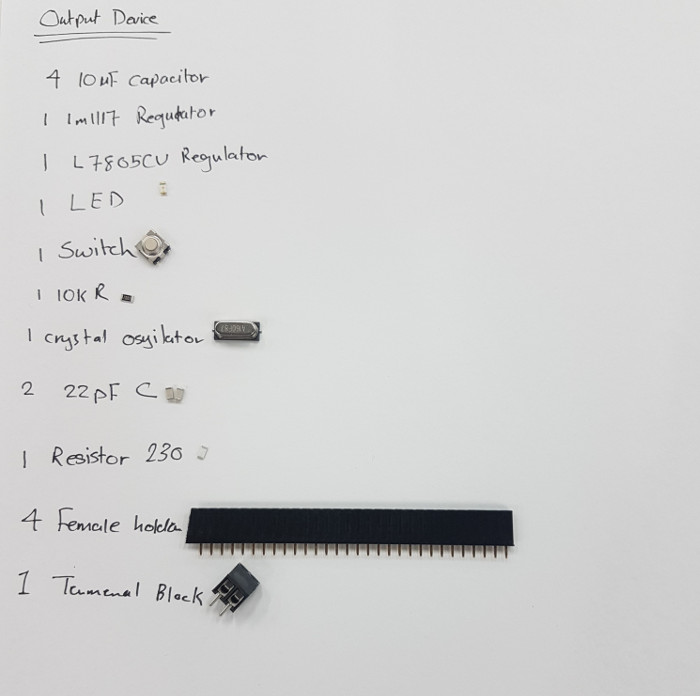
The components and the fabricated PCB of the output device is the following:
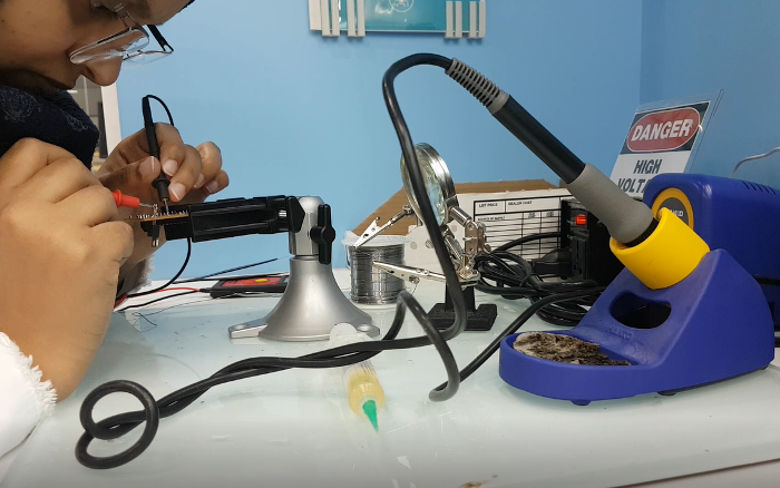
Testing
The final testing of the output device worked perfectly with the fabricated PCB: