Molding and Casting: Be Creative!
In this assignment we are suppose to design and mill a counter mold and then cast it to create a 3D object. For this assignment I decided to do something I have never tried before, which is designing a jewelry piece. I am not a designer, however I followed an online tutorial on how designing a ring using Rhino. You can find this tutorial here!.
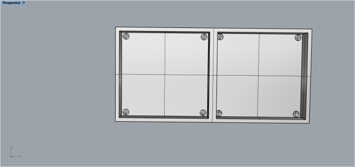
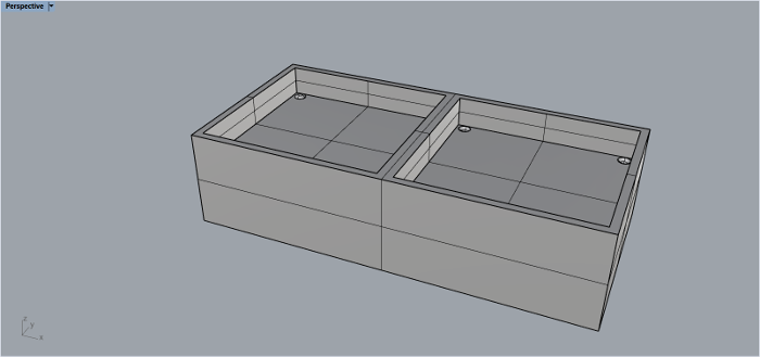
Counter mold design
At the beginign I started with creating the 3D object it self. I used Rhino for the 3D modling, as I mentioned up I followed an online tutorial to design the ring. The designs steps are the following:
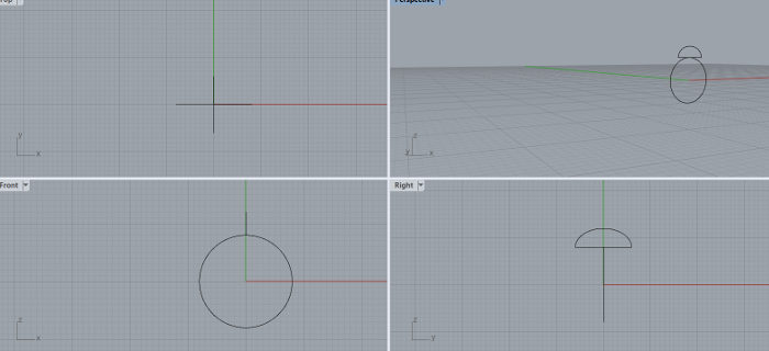
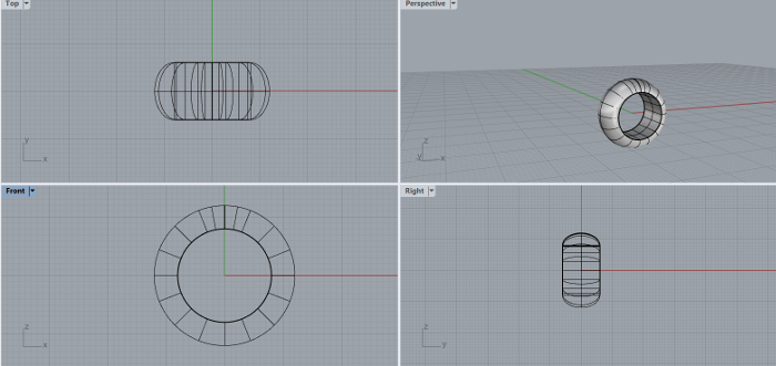
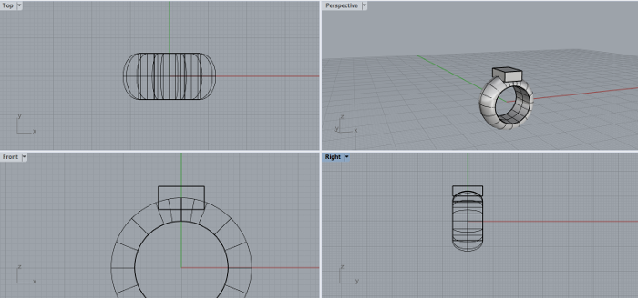
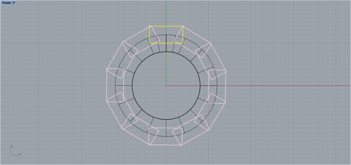
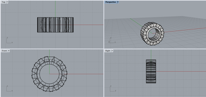
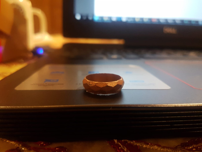
It was hard for me to follow the tutorial exactly, at some point I had to change few things to reach the final results. However, I am extremly happy of how the 3D object turned out eventually. Here is the final result:
Mold milling process
The next stage after desiging the mold was to start the milling process. In our lab we have the Roland MDX-50 milling machine which I am going to use for the milling process. This machines comes with liceaned software called the SRP Player CAM which I am going to use to prepare my file for the milling process.
First step is to ensure that the tool I am going to use is available in the tools’ library. Go to Options → My tools. This will open the library of the predefined tools. In case the tool you are using is not available, you need to add it first.
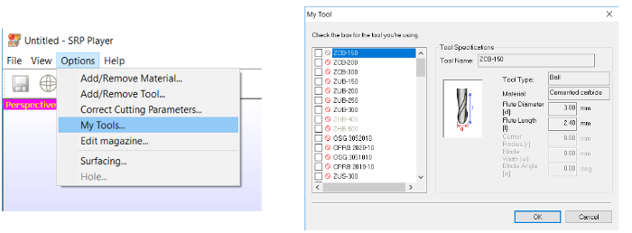
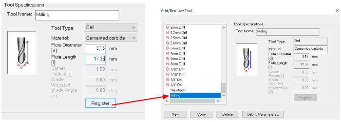
Then I moved to Options → Add/Remove Tool, to add new tool. A window with Tool Specifications will open up. Give the tool a name, select the tool type and fill the remaining specifications, for the tool I am going to use for the milling.
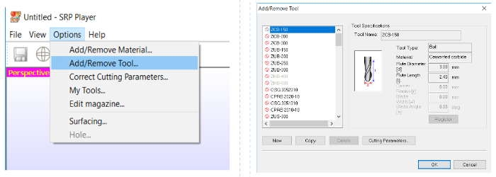
Once the tool is registered, it will appear in the tools’ list as shown above. And this is how I registered the tool Iam going to use for the milling process.
After preparing the tool, I imported my mold to the software so I can adjust its settings in terms of the object size, material type and size, milling quality and resolution and the tool type and slot in Roland MDX-50 tools’ rack before the milling process.
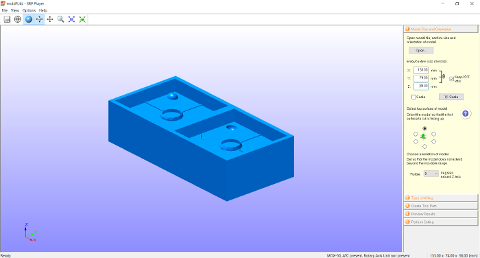
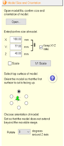
First I adjusted the size of the 3D model to fit into the wax brick.
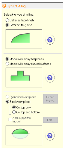
Then I edited the milling type. This need to be done wisely as it will affect the milling time.
Next step is to edit and create the tool path of the milling. First added the size of the wax brick, then click Edit. This will open a window where I have two profiles; one for rough milling and the other for finishing.
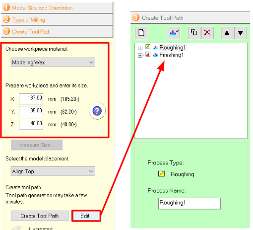
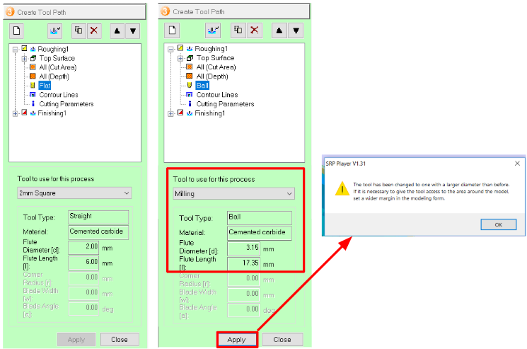
Select the "Roughing" to see the different options under roughing. Change the bit from "flat" to "Ball" by changing the tool from 2mm Square to Milling -the added new tool-. Then click Apply and a pop up box will appear telling you that the change of the bit will cause some changes in the milling process. Click Ok.
Now you need to edit the finishing tool. Click on "Finishing" to see the options for finishing and edit the tool as shown.
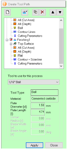
Select Contur + Scanline. It is advised to edit the scan lines direction to be in the Y direction since roughing is in the X direction starting from the lower right corner. Then I went back and click on Create ToolPath. The software will generate the paths for both the roughing and the finishing based on some calculations dependant on the tool type, diameter, etc. Refer to the figure above.
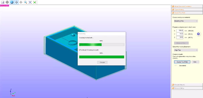
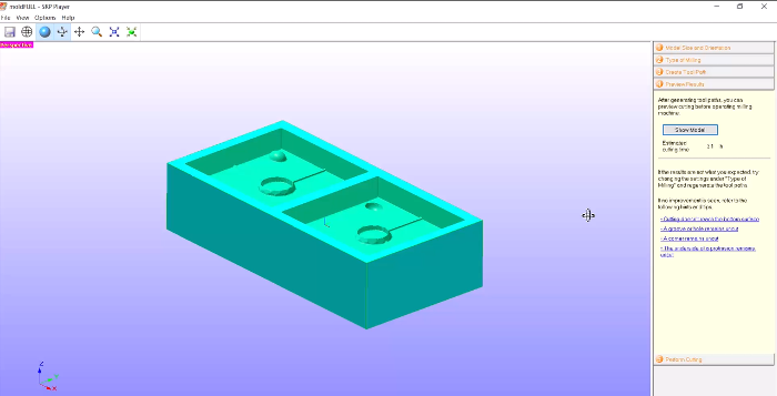
Now the software will tell you how much your model will need. Here it was 2 hours. The milling can be reviewed by simply selecting Preview Cutting which will take few seconds and then shows the millied piece shown at the right side.
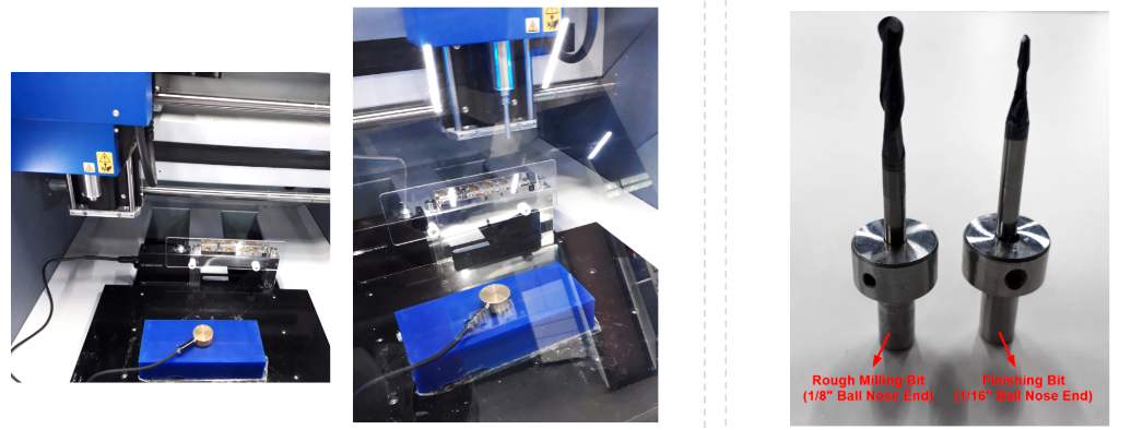
Prepare the wax brick by attaching it into the machine milling bed using double phase tissue tape and use the Z-probe along with detection pin for Z0 sense measurement as done before. Prepare the milling bits. ⅛” Ball End for rough milling and 1/16” Ball End for smooth finishing. Place the tools in slot 1 and 2 respectively in the machine.
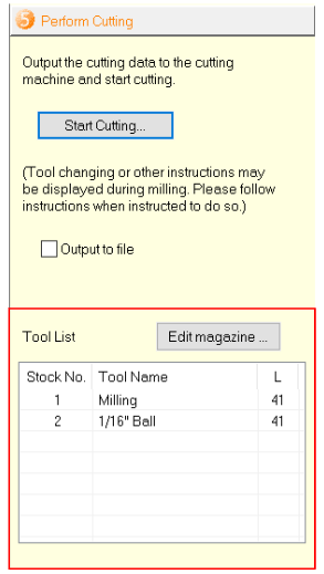
Now the last stage before cutting and sending the file to the machine. It is important to ensure that the two milling bits are added to the magazine and specify the slots where they will be actually place in the tool holder. Finally click Start Cutting.
The software will double check few things related to tools, origin of the workpiece and Z0 level then will allow you to start the cutting process.

When the process is finished, the software will show “Cutting is finished” and Roland LEDs will turn blue.
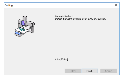
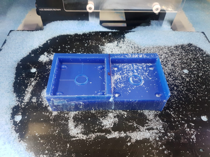
And by this the milling the process will be done and here is the final results. A mistake happened when I was adjusting the position of my origin but still the mold is acceptable and I can use it for creating my counter mold.
Create the second counter mold
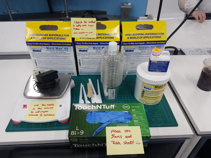
After finishing the milling process it is time now to create the counter mold. For that I used Mold Max™ 10. I refered to the datasheet to check the pot time and cure time for the material, in addition to the mixing volumes and preferred temperature.

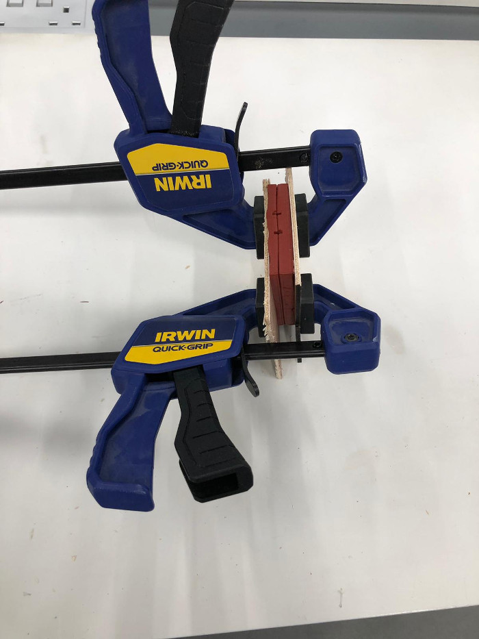
I mixed together a volume of 100A:90B, and poured it into the milled wax molds. I then waited for 24 hours for the counter mold to finish. Me and my Fab Academy team did a timelapse video to illustrate the process.
Casting process
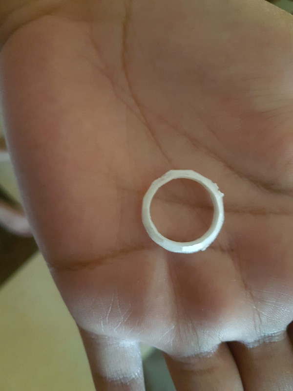
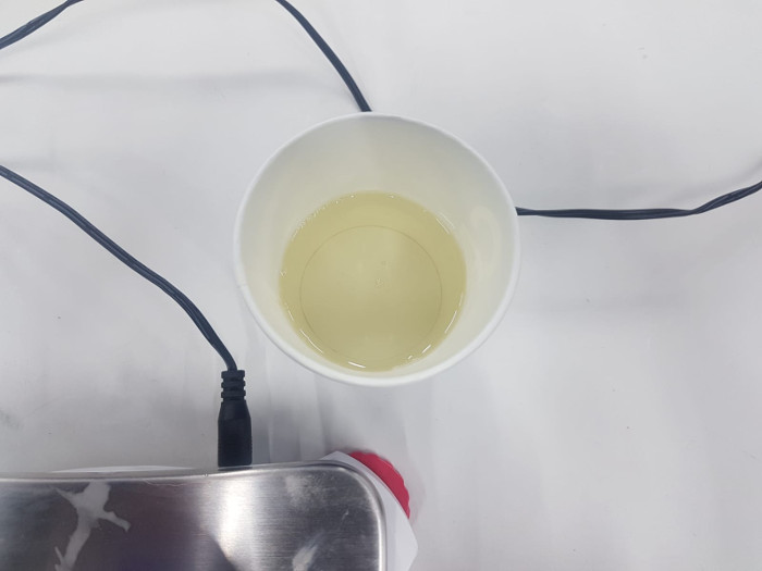
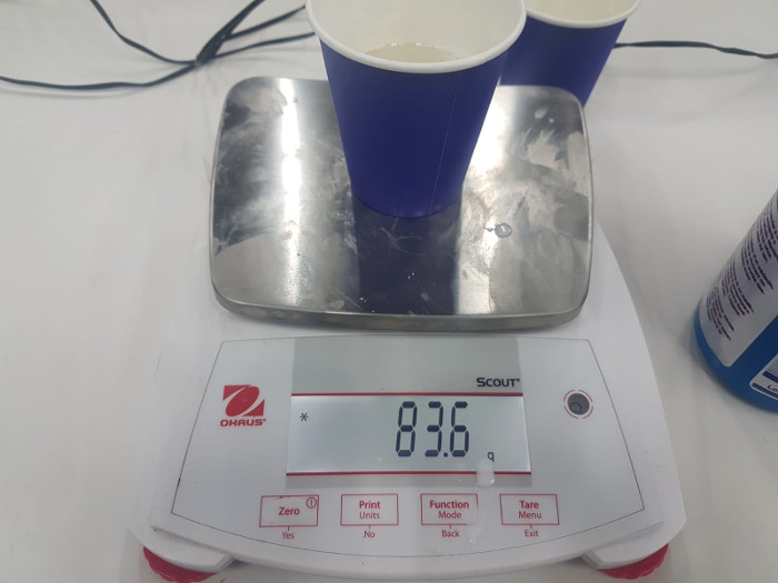
Finally After I was done with creating the counter mold I casted it using the Smooth-Cast® 300, and put equal amounts from each A and B, I consumed almost 84 grams from each container to create my casting material. The process was actually easy and the results turned out perfectly good.

And the final results are the following. The casted ring was white then I spray painted with copper paint. The experiment was actually fun and I really enjoyed doing the process.
