Task 12
Output devices
In this week, I was given a task to have a group assignment and an individual assignment. The group assignment was to measure the power consumption of an output device, and the individual assignment was to add an output device to a microcontroller board you've designed, and program it to do something
Individual Task
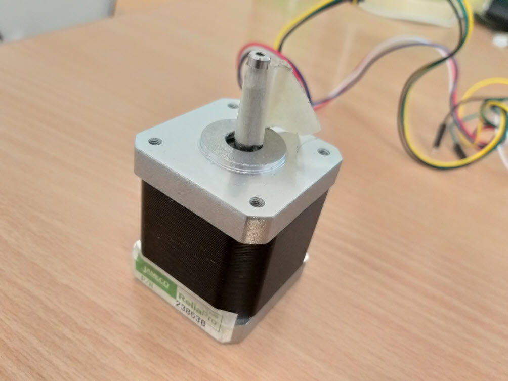
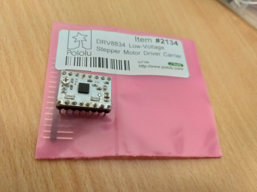
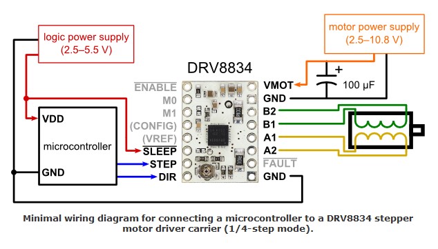
For this week, I started with the Individual work. I decided to use stepper motor as my output device since I will be using it for my Final Project therefore it was better to learn how to control the stepper motor in advance. In order to know the working of the stepper motor the Tutorial 1 and Tutorial 2 were really helpful inorder to know the basics of stepper motor. The Stepper Motor that I decided to use was Bipolar Stepper Motor 4.5 VDC 1500 mA 1.8°/200 steps which was available at our Fab Lab. To control the Stepper Motor, we require a driver, for this purpose I used DRV8834 Low Voltage Stepper Motor Driver Carrier, the datasheet was studied which provided info about the connections possible to make with the stepper. The connections were being made according to the hobbytronics website The below diagram demonstrates that:
Programming the Board
In order to program the board, I utilized the Simple Stepper Motor Control Example Code by Dejan Nedelkovski. I did some modifications in the code. First we have to define the Step and Direction pins. In my case they are the pins number 7 and 8 on the Arduino Board and they are named stepPin and dirPin and the setup section we have to define them as an outputs. In the loop section first we will set the Direction pin on high state that will enable the motor to move in a particular direction. Now using this for loop we will make the motor make one full cycle rotation. As the driver is set on Full Step Mode and our Stepper Motor has 1.8 degrees step angle , or 200 steps, (360 degrees/200 pulses = 1.8 degrees) thereby we need to send 200 pulses into the Step Pin to make one full cycle rotation. So the for loop will have 200 iterations and each time it will set the Step pin on high and then low state for making the pulses. Between each digitalWrite we need add some delay from which the speed of the motor will depend.
// defines pins numbers
const int stepPin = 7;
const int dirPin = 8;


void setup() {
  // Sets the two pins as Outputs
  pinMode(stepPin,OUTPUT);
  pinMode(dirPin,OUTPUT);

}
void loop() {
  digitalWrite(dirPin,HIGH); // Enables the motor to move in a particular direction
  // Makes 200 pulses for making one full cycle rotation

  for(int x = 0; x < 200; x++) {

    digitalWrite(stepPin,HIGH);
    delay(50);  // ms (Note : 1000ms = 1sec)

    digitalWrite(stepPin,LOW);
    delay(50); // ms (Note : 1000ms = 1sec)
  }

}
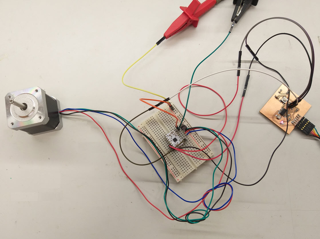
After making the code for the testing, I did the Initial tests on Week 07 echo hello-world board to check whether the motor, driver and the connections are correct and the program is running smoothly. The driver was connected on the bread board and the connections were made. After Uploading the Code, The Motor was rotating and performing as expected completing one full rotation. The watch clock timer was used to clock the time of 1 complete rotation cycle and it satisfied the coding that I did.

Board design and fabrication
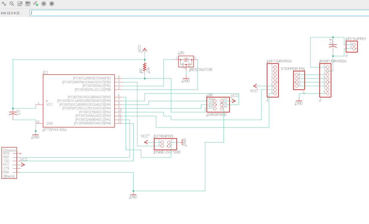
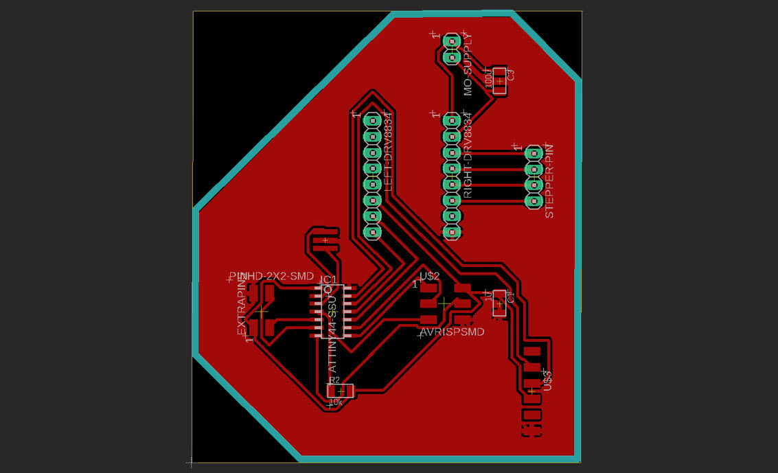
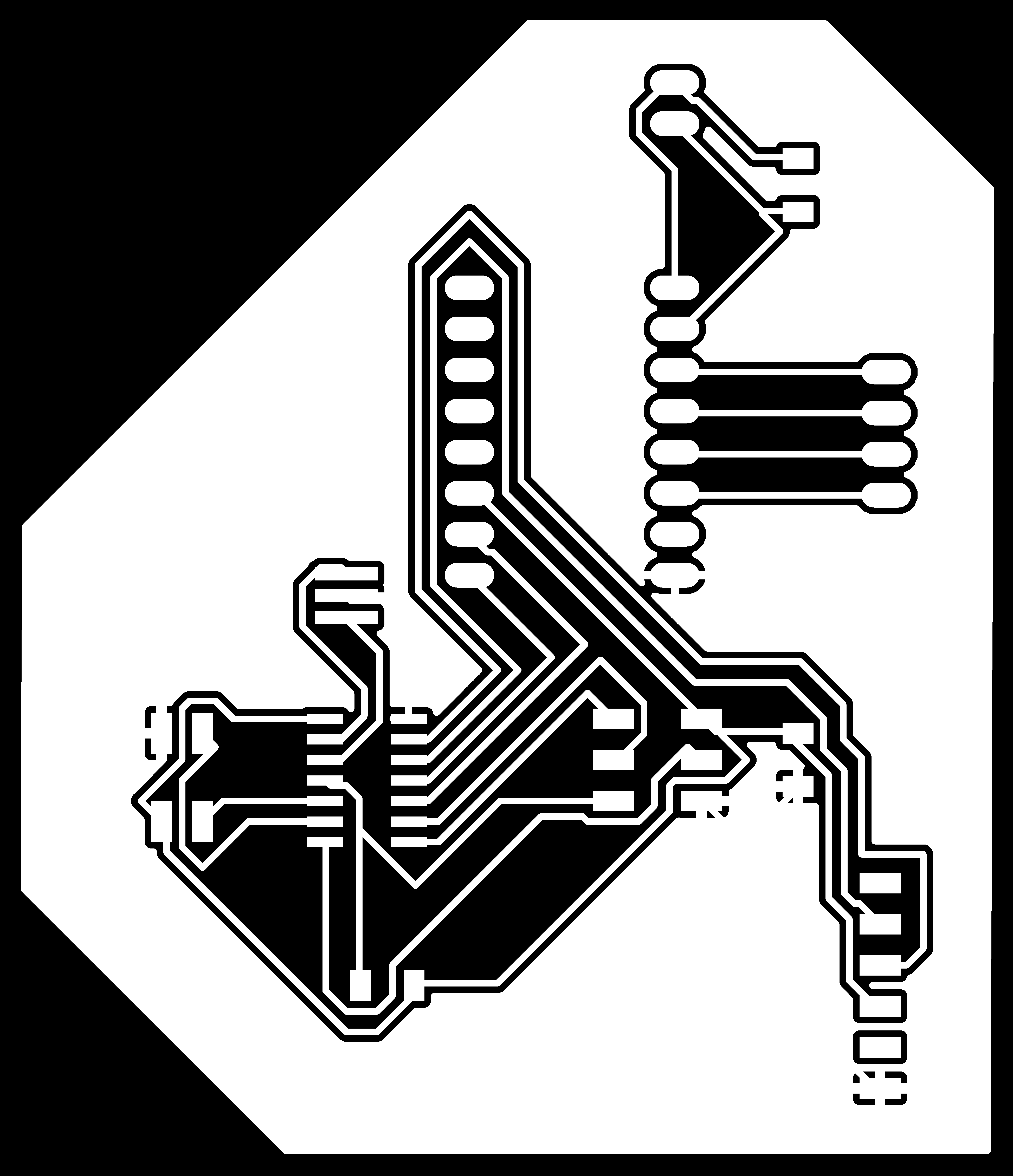
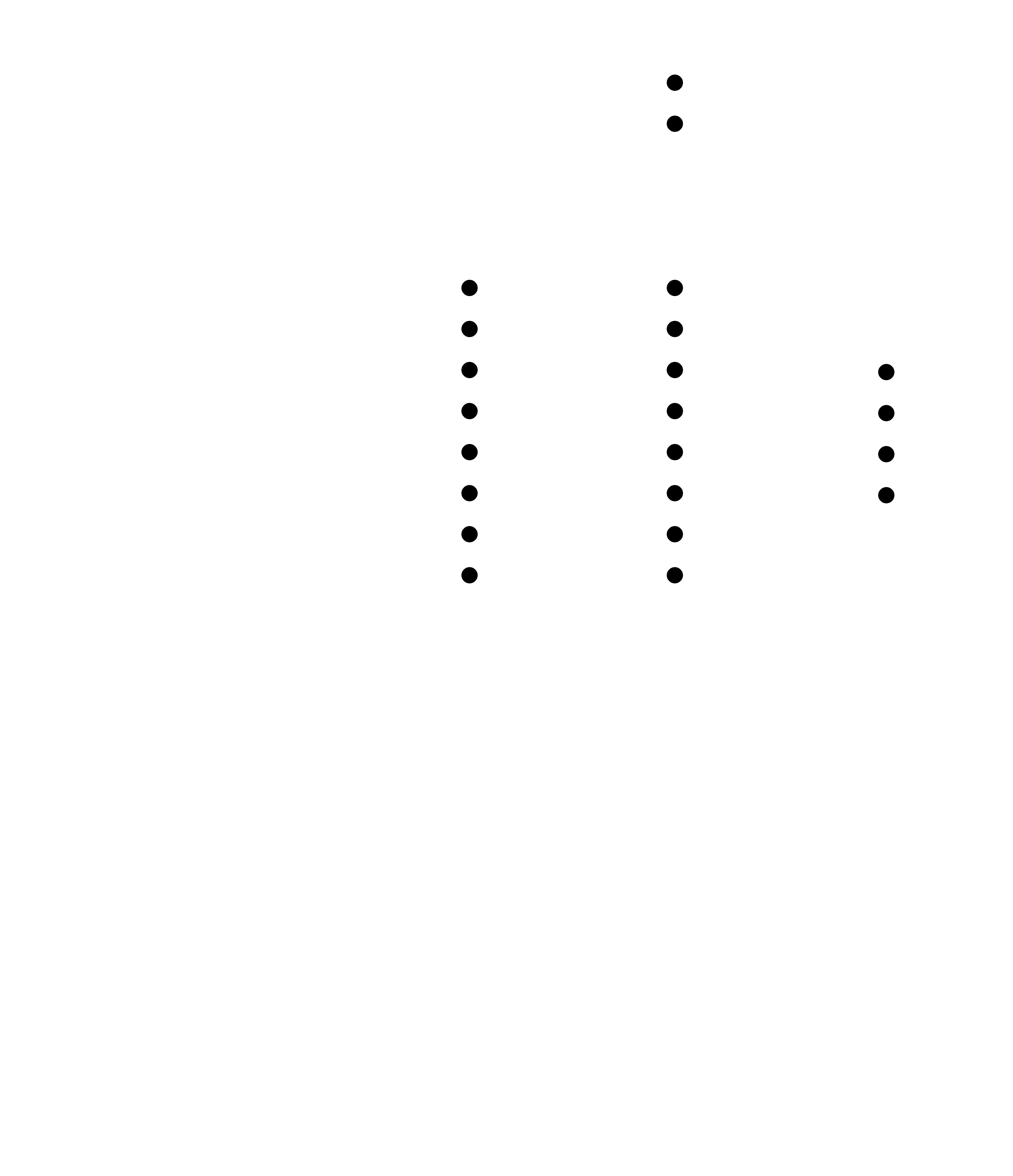
I designed a new schematic for my output device board using Attiny 44A with rails to mount the stepper controller. For this purpose, I followed the previous Week 05 and Week 07 documentatin to follow the design rules, milling and soldering . The Board schematic is given in the figure below
- Below Compoenents were being used on the board for soldering:
- ATtiny 44A
- 3x3 pin headers
- Resistor 10k
- Resonator 20MHz
- Capacitor 1UF
- Capacitor 220uF
- FTDI Header
- rails 8*1-2,2*1-1,4*1-1
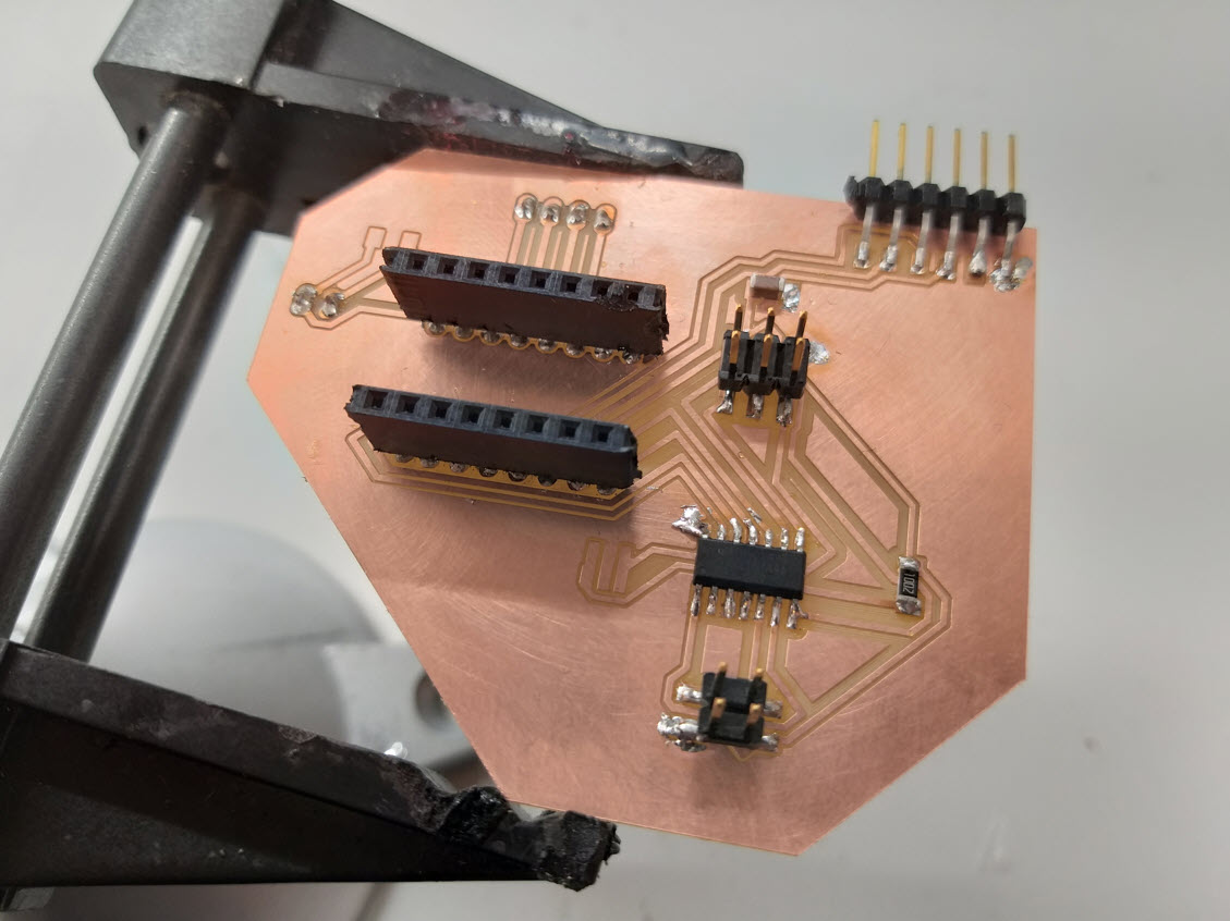
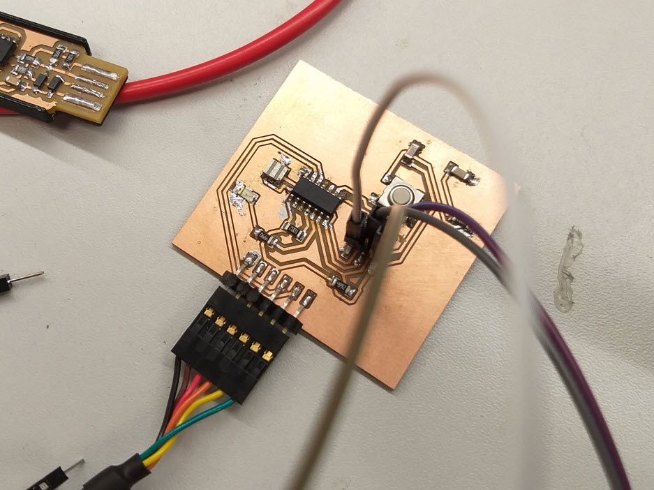
Testing the designed Board
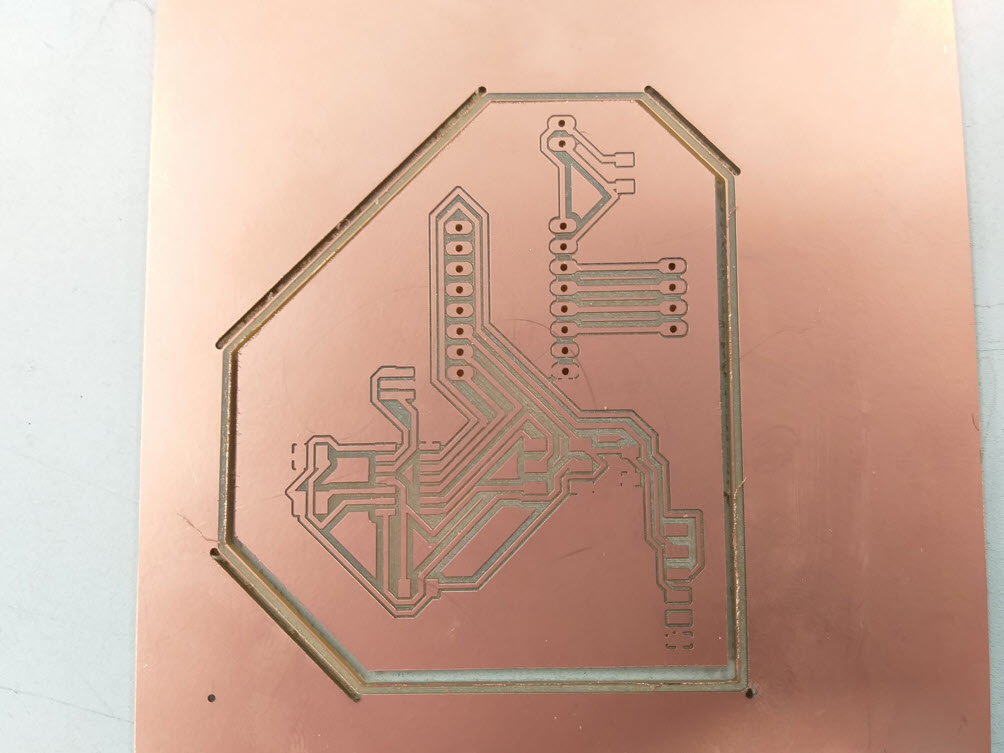
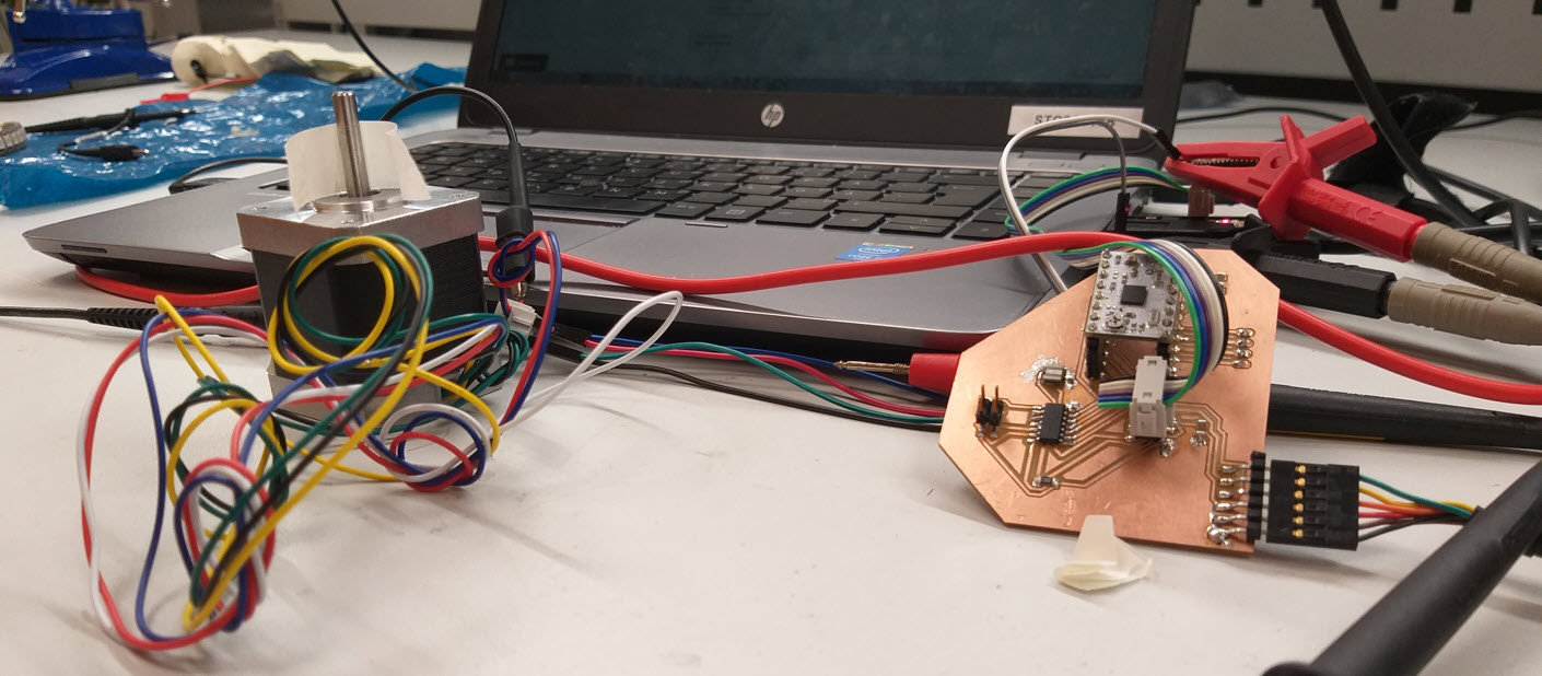
After Milling and soldering the Board, the final task was to test the designed board, I did the connections privided VCC(5V) and GND to the controller and VDD(2.5 to 10V) to the driver and uploaded the code. It was a succcess, the code was uploaded successfully and the motor was running perfectly and output of the driver to the motors was observed to be in pulses given to the stepper motor to move in steps.
Group Work
For this task, me, Alok, Jobin, Sahan, and Micheal measured the power consumption of a 5 mm LED and an RGB LED (the one used in the individual assignment above). The consumption of the LEDs was measured by directly powering them with a variable power supply and voltage and current were the parameters that were being varied in order to measure the resulting effect on the brightness of the LEDs.
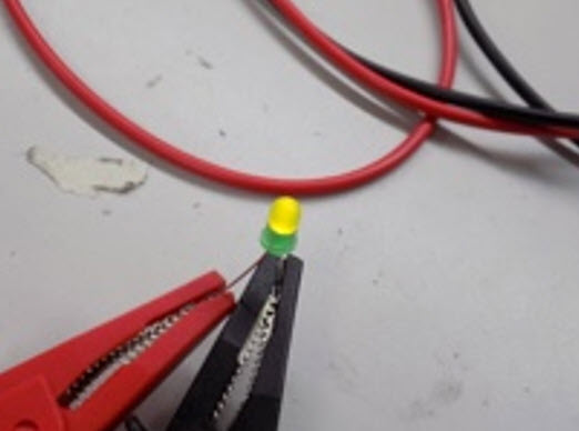
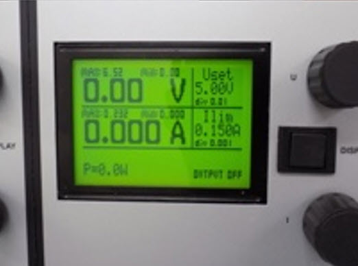
In both tests, we burnt out the LEDs by exceeding their voltage and current limits. For the 5 mm LED this was 6.5 V and 188 mA (it is probably lower than these values). Blue and Green LEDs can be fed with a maximum current of 100 mA (Peak Forward Current) for a very short time without being damaged 2. The peak forward current is the absolute maximum current that an LED can handle and this is only for a short period of time. The peak forward current, specified on a datasheet, can only be applied to an LED for the time period specified. This time period is either specified as a fraction of a duty cycle or as a time in millisecond
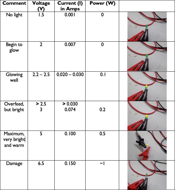
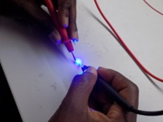
For the RGB, we repeated the same process as with the 5 mm LED, testing the effect of varying the voltage and current on the brightness. If current is increased the LEDs brighten and if decreased, the LEDs become dimmer. According to the data sheet, this LED has Forward Voltage ranging from 2 - 4 V. 2 - 2.6 V for Red, 3.2 - 4 V for Green, and 3.2 - 4 V for Blue. The absolute maximum ratings for the Forward Current (the current flowing across the LED from positive to negative in order for the LED to get power) for Red is 50 mA and for Green and Blue it is 25 mA (milliamps) when powered individually as we did. We tested the power consumption from a low of 1.60 V and 0.001 Amps, which didn’t power on the LED, to a high of 6.5 V and .200 A. Red was very dim at 1.9V and 0.001 Amps and the optimal value was 2.3 V and 20 mA. With the recommended electrical characteristics of 20 mA, Red has an average forward voltage of 2.0 V, Green 3.2 V, and Blue 3.2 V, respectively.
Resources Utilized
- I utilized these resources for this task:
- Arduino IDE
- Eagle
Files
- Arduino Code : Stepper
- Output Board : Schematic (.sch) file
- Output Board : Layout (.brd) file
- Board Traces : Excluding Holes for Rails (.PNG) file
- Board Traces : Excluding Holes for Rails (.RML) file
- Board Traces : Including Holes for Rails (.PNG) file
- Board Traces : Including Holes for Rails (.RML) file
- Board Outline : (.PNG) file
- Board Outline : (.RML) file