04/ electronics production
This week we learn to produce a programmer FABISP base on an exisiting design.
Links to the sections below:
1. Group Assignment
2. Make a programmer FABISP
← previous
→ next
⋯ assignment list
🏁/ final project
Group assignemnet
Punch cards also known as Hollerith cards and IBM cards are paper cards containing several punched or perforated holes that were punched by hand or machine to represent data. These cards allowed companies to store and access information by entering the card into the computer. I'm thinking of making paper tape holds data as patterns of punched holes.
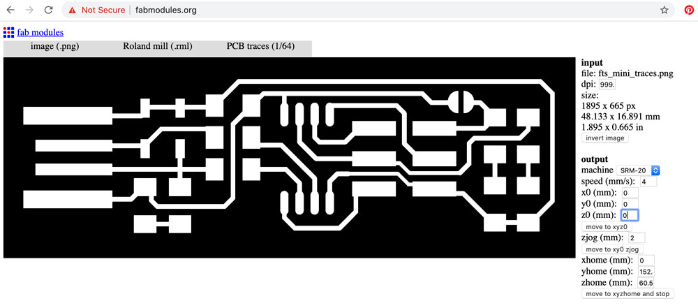
In the software, first we need to set the original X/Y position by moving the endmill to ideal position and hit set original point X/Y.
Then we set original Z position by:
- 1. Move endmill down with single steps until it is about 5mm to the plate.
- 2. Loosen the screw using a special stick tool, and gently land the endmill so its tip-point touches the plate.
- 3. Slightly pushing the endmill down, tighten the screw using the same tool.
- 4. Set original point Z in control panel.
- 5. Raise the Z position up 2mm to ensure the endmill will not scratch copper surface when it moves around.
Now we can hit cut in control panel, upload the exported .rml file and start printing. The plate we use is a FR1 board, which is made up with a thin layer of copper and phenolic paper that is easy to mill.
After done with engraving and cutting, we take the board away from the plate, remove double-sided tapes from the back, use knife to scratch out the unecessary parts, put on some Acetone to clean the surface with brush, and the board is ready for soldering.
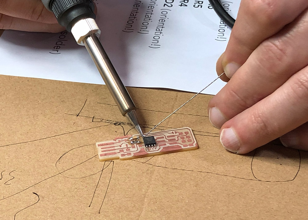
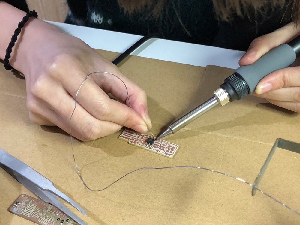
For soldering we use tools such as soldering iron, tweezer, electrical wire, desoldering braid, magnifying glass + lamp, stereo zoom microscrope, and etc.. To solder all components well on to the board, it takes great patience and caution since some components have directions.
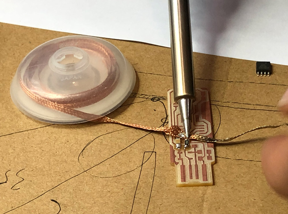
Solder braid can be life-saver for beginners.
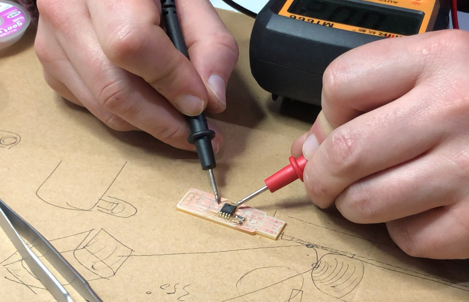
Multi-meter is one other handy tool to help check if circuits can go through component joints.
After done with soldering, connect the new board to an existing progammer with wires and we can start programming the new board.

Making a programmer FABISP
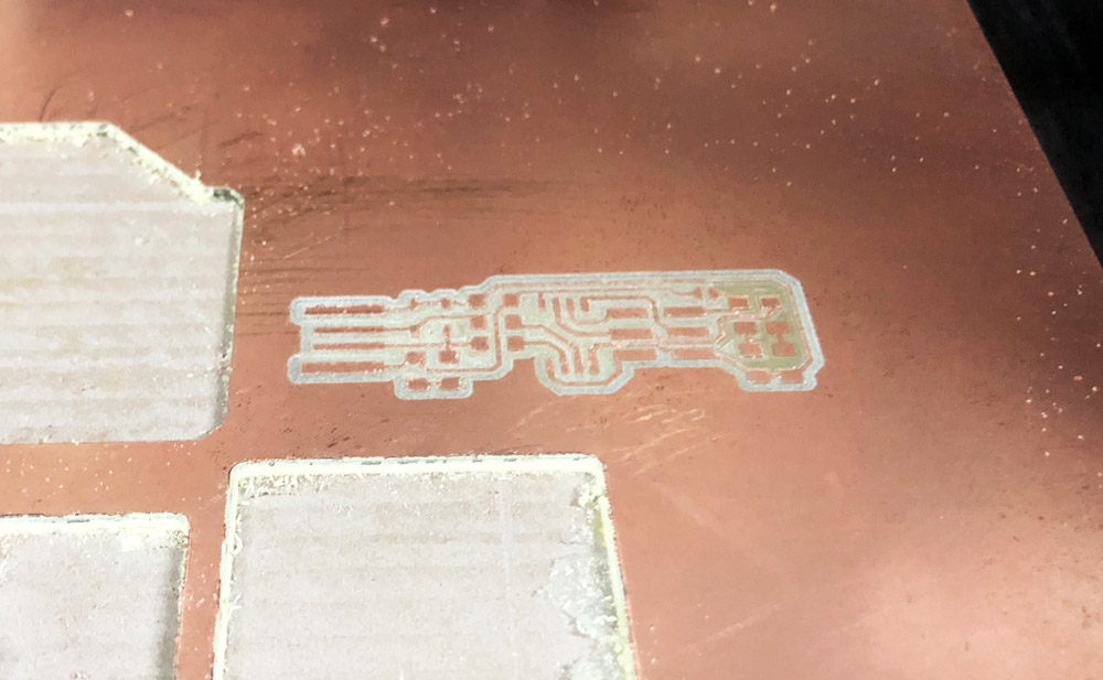
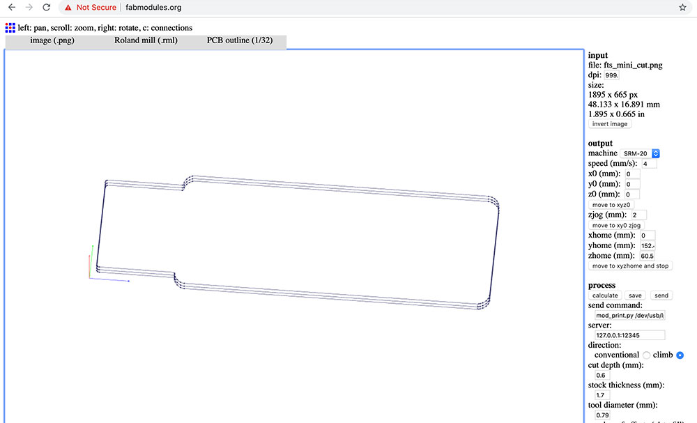
Base on Bryan's board design, I slightly personalized it by adding the little pac-man graphics in the bottom empty area :D
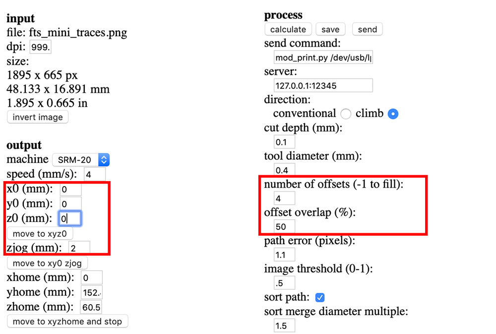
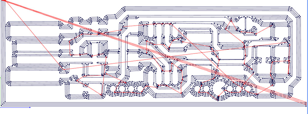
After I was happy with the settings, I hit calculate under process to see the route that endmill will follow through. Then I export and download the .rml file.
Then I uploaded the cutting png and adjusted settings for cutting.
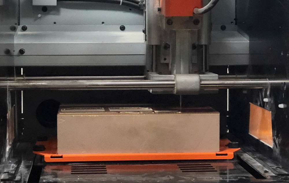
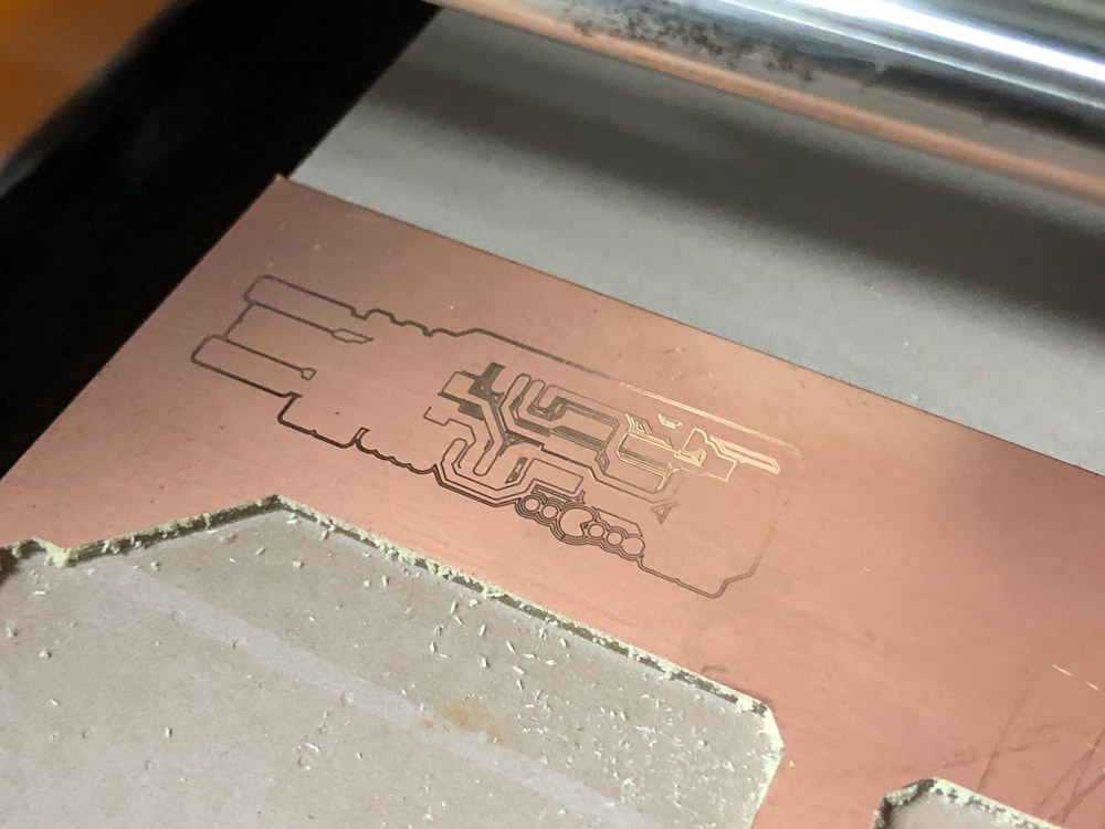
When the engraving process started, I soon realized something was going wrong, because the trace looked very shallow and the mill did not go through the copper layer. After inspecting the control panel setting and the machine, it turned out to be two reasons: The main reason is because I did not screw the endmill very tight so it might have moved up a little bit during printing. The other reason was that the mill head was already very blunt. After the endmill get screwed tight, it started to print normally.
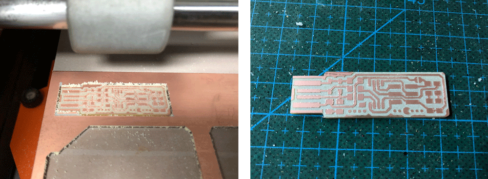
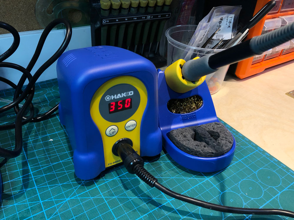
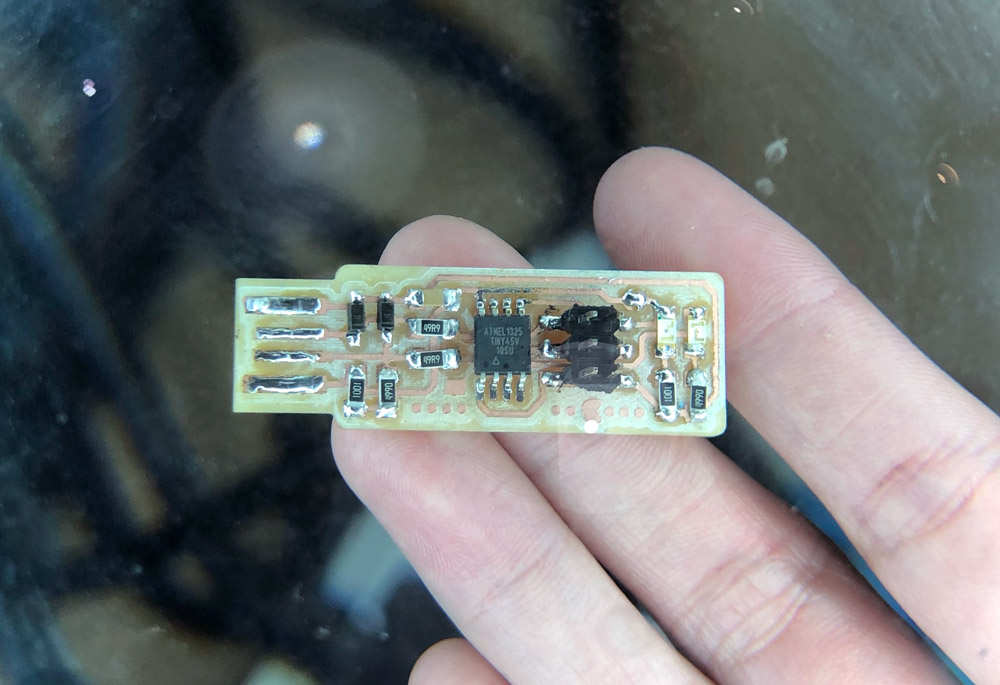
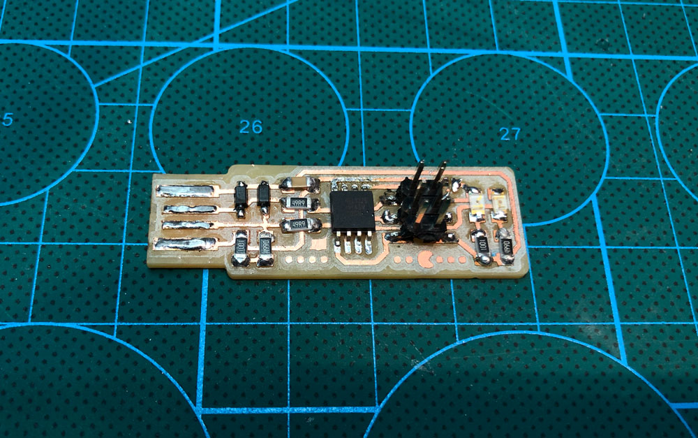
The plain board looks nice :D After cleaning up the board, I soldered the components onto the board. The temperature I used for soldering iron is 350 degree C. It was tricky soldering the multi-leg components (better use desoldering braid) and figuring out the direction of LED (to tell from its back).
After finish soldering the next step was to program the new board. I installed CrossPack, downloaded the firmware source code and extracted the zip folder to get a folder named fts_firmware_bdm_v1. Inside that folder there was a Makefile. We can use any text editor to open and and edit that file, changing the PROGRAMMER to common stype programmers' names. For me, since I am using a FABISP with an ATtiny on it, I keep it as usbtiny.
(Go to Brian's site for download links and more detailed explaination.)
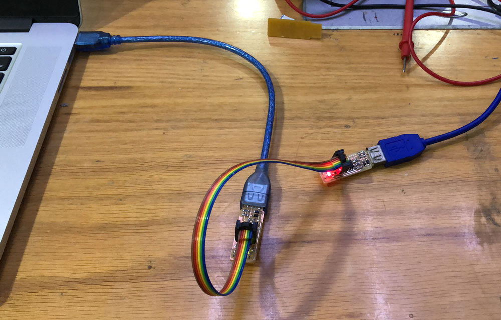
I connected the programmer with my laptop using a USB extension cable; my new board's 2x3 pin header to the programmer's pin header using the cord I made; and new board's usb port to external power source using a USB extension cable.
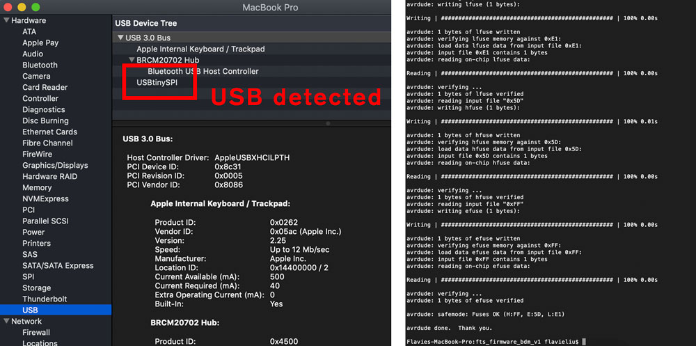
In terminal on mac, I cded to the fts_firmware_bdm_v1 folder, ran make. Then make flash. An connection error message came up, although my laptop was able to detect the ISP :(
After I double-checked the solder joints with multi-meter and restarted my computer a few times. The make flash command magically worked :O My guess was there was some intermittent connection somewhere on my board.

Then I ran make fuses. This is to make sure the board works as a USB device and can use its reset pin to program other boards. After that I disconnect the programmer and connected the new board to my laptop with an USB cable to check if my computer can detect the board.
Then I went back to the previous connection setting (programmer to laptop and board, board to external power) and run make rstdisbl. This is to disable the ability to reprogram this ATtiny45 in the future. I got some error messages about connections several times, and fortunately it worked out finally.
The last step was to disconnected the bridge on the solder jumper, and I got my own ISP programmer!!!
(Updated 02.19.2019)