🏁/ final project
This page documents how my final project gets developed through out the semester:
1. initial ideas and sketches
2. electronics
3. fabrication
4. programming
5. BOM
6. licensing
→ next
⋯ assignment list

One minute video introducing my project:
Initial ideas and sketches
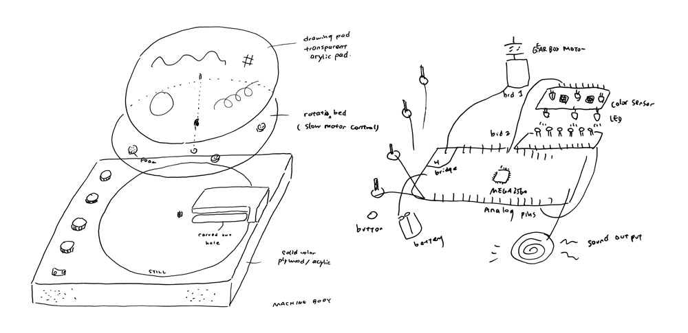
Inspired by the principle and machanics of the Oramics Machine, I will design a drawing music instrument that allows user to draw graphics by freehand as input and have instrument produce sound accordingly.
More details for the idea and project plan go to:
12/ applications and implications week page.
Electronics
For the electronics there are two main parts, the sensors detecting light change and the motor spinning the disk. The MCU chip I use is ATmega328. The chip has enough output pins to control both sensors and motor, as well as an output microphone.
First I did a test with two types of photoresistors and a phototransistor to understand which would be the best sensor to use.
This youtube video Photodiode vs Phototransistor vs Photoresistor compares the response times of the three sensors with an oscilloscope.

Base on the test I did under room light, the photoresistor and phototransistor worked very similarly. The photoresistor gave more obvious changes in reading and reacted slightly faster than the phototransistor so I decided to go with it.
Here is the test I made with photoresistors on a breadboard.
Base on the test I made my first photoresistor board.

Later I find out the spacing between the photocells is too close and two cells have trace touching each other thus not reading well. I also do not need 15 sensors because ATmega328 chip have no more than 8 analog input pins. So I made a second board.


I first decide to use a regular dc motor but Saverio suggestes that the motor will spin too fast for my case and it may not provide enough torque(turning force) if I slow it down using pwm. The best way is to physically slow down the motor by adding a gear system to the motor output and there is a special kind of gearbox motor I can use.

The next step is to make a motor driver board because the dc motor cannot connect to ATmega328 directly. I tried to make a board with A4953 h bridge motor driver based on Neil's example board. I took out the chip thinking I could use this board as module connecting my FLAVINO.


This board did not work. When it was connected to FLAVINO the voltage regulator and ATmega328 got super hot and the chip was burnt :(
I made another attempt bringing back the ATTiny44 chip on the board. I found a previous student's documentation on the same h bridge, and liked that he added additional button to control rotation direction. So I redrew Neil's example board and added three buttons in addition to that.


While bootloading the board I got some error messages. Later Saverio found out I was using the external 20MHz fuse setting (used for the echo hello-world board) to set fuse to the chip, but I did not put any external clock on my board. I need to recalculate fuse with internal 8MHz clock. Then I was able to bootload my board.
But I was never able to drive the motor using this board... Saverio and I spent a lot of time checking connections of the traces. The connections were fine. We replaced both ATTiny44 chip and h bridge chip. It still did not work. I then milled Neil's motor board without doing any changes, that board also did not work. I guess the problem came from the h bridge, which is like a myth :(
Then I switched to a simpler motor driver L293. The chip can control two motors at the same time. You can change speed using pwm and direction with it, which is all I need. I designed a new module board.


Finally this board works with FLAVINO and gearbox motor :D
The default motor speed (without pwm) changes with input voltage. In the video I use a 12V power adapter and the motor spins pretty fast. 5V input makes motor rotate at a slow speed but the spin gets jaggy when I try adjust pwm with 5V power level. 9V is a good voltage level but 9V battery does not have enough current for the whole system especially after I add amplifier and speaker. Ideally the best setting for power is 9V/2A from the bench power supply. Otherwise 12V power adapter will work for it.
For the control board I'm using FLAVINO2.0. The ATmega328 chip allows up to 8 analog input pins, which is enough for the prototype. I may try extend the number of analog input pins using an ATmega2560 chip or explore board to board communications. Since I do not have enough VCC/GND pins on FLAVINO I used power regulation board I made before as pin extension board. The power regulation is not necessary and you can use any type of connectors instead.
For details of how to make a FLAVINO or power regulation board go to networking and communication week.
↓ download files:
Fabrication
For the box I decide to use solid color acylic for the surface and transparent one for the inner structure. I made a kerf test for 5mm acylic board with our laser cutter and designed the 2D trace in Illustrator with careful calculation.


↓ download laser-cut files: laser_cut_box.ai, laser_cut_box.pdf
For the small parts such as motor holder, buttons and potentiometer caps I modeled them in Rhino and 3D printed them.


↓ download files:
Programming
For each photoresistor I tested the reading when the graphics block the light. Then I define the triggering event. When the reading decrease to a certain value, the speaker will output a note related to the photoresistor. In my final prototype 6 photoresistors are assigned 6 different notes.
Below is my main code:
#include "pitches.h"

const int pResistor1 = A1;
const int pResistor2 = A2;
const int pResistor3 = A3;
const int pResistor4 = A4;
const int pResistor5 = A5;
const int pResistor6 = A0;

const int pot1 = A6;
const int pot2 = A7;
const int button1 = 5;
const int button2 = 6;

const int motorin1 = 2;
const int motorin2 = 3;
const int enable = 9;

int potvalue1;
int potvalue2;
int pwm1;
int pwm2;

int notes[] = {
  NOTE_E4, NOTE_G4, NOTE_B5, NOTE_D5,NOTE_G5,  NOTE_B6, NOTE_C6};


int value1;
int value2;
int value3;
int value4;
int value5;
int value6;

void setup(){
 Serial.begin(9600);

 pinMode(button1, INPUT);
 pinMode(button2, INPUT);
 pinMode(pot1, INPUT);
 pinMode(pot2, INPUT);
 pinMode(motorin1, OUTPUT);
 pinMode(motorin2, OUTPUT);
 pinMode(enable, OUTPUT);

 digitalWrite(enable, LOW);
}

void loop(){

  potvalue1 = analogRead(pot1);
  pwm1 = map(potvalue1, 0, 1023, 255, 0);
  potvalue2 = analogRead(pot2);
  pwm2 = map(potvalue2, 0, 1023, 255, 0);
  Serial.print(pwm1);
  Serial.print(" ");
  Serial.print(pwm2);
  delay(10);

  analogWrite(motorin2,pwm1);

  if(digitalRead(button1) == LOW){
    digitalWrite(enable, HIGH);
    digitalWrite(motorin1, LOW);
    digitalWrite(motorin2, HIGH);
  }

  if(digitalRead(button2) == LOW){
    digitalWrite(enable, HIGH);
    digitalWrite(motorin1, HIGH);
    digitalWrite(motorin2, LOW);
  }

  value1 = analogRead(pResistor1);
  delay(10);
  value2 = analogRead(pResistor2);
  delay(10);
  value3 = analogRead(pResistor3);
  delay(10);
  value4 = analogRead(pResistor4);
  delay(10);
  value5 = analogRead(pResistor5);
  delay(10);
  value6 = analogRead(pResistor6);
  delay(10);

  Serial.print(" ");
  Serial.print(value1);
  Serial.print(" ");
  Serial.print(value2);
  Serial.print(" ");
  Serial.print(value3);
  Serial.print(" ");
  Serial.print(value4);
  Serial.print(" ");
  Serial.print(value5);
  Serial.print(" ");
  Serial.println(value6);


  if (value1 < 970){
    tone(8, notes[0], 20);
  }

  if (value2 <970){
    tone(8, notes[1], 20);
  }

  if (value3 < 970){
    tone(8, notes[2], 20);
  }

  if (value4 < 970){
    tone(8, notes[3], 20);
  }
  if (value5 < 970){
    tone(8, notes[4], 20);
  }
if (value6 < 970){
    tone(8, notes[5], 20);
  }

}
And here is the seperate code defining pitches:
/*************************************************
 * Public Constants
 *************************************************/

#define NOTE_B0  31
#define NOTE_C1  33
#define NOTE_CS1 35
#define NOTE_D1  37
#define NOTE_DS1 39
#define NOTE_E1  41
#define NOTE_F1  44
#define NOTE_FS1 46
#define NOTE_G1  49
#define NOTE_GS1 52
#define NOTE_A1  55
#define NOTE_AS1 58
#define NOTE_B1  62
#define NOTE_C2  65
#define NOTE_CS2 69
#define NOTE_D2  73
#define NOTE_DS2 78
#define NOTE_E2  82
#define NOTE_F2  87
#define NOTE_FS2 93
#define NOTE_G2  98
#define NOTE_GS2 104
#define NOTE_A2  110
#define NOTE_AS2 117
#define NOTE_B2  123
#define NOTE_C3  131
#define NOTE_CS3 139
#define NOTE_D3  147
#define NOTE_DS3 156
#define NOTE_E3  165
#define NOTE_F3  175
#define NOTE_FS3 185
#define NOTE_G3  196
#define NOTE_GS3 208
#define NOTE_A3  220
#define NOTE_AS3 233
#define NOTE_B3  247
#define NOTE_C4  262
#define NOTE_CS4 277
#define NOTE_D4  294
#define NOTE_DS4 311
#define NOTE_E4  330
#define NOTE_F4  349
#define NOTE_FS4 370
#define NOTE_G4  392
#define NOTE_GS4 415
#define NOTE_A4  440
#define NOTE_AS4 466
#define NOTE_B4  494
#define NOTE_C5  523
#define NOTE_CS5 554
#define NOTE_D5  587
#define NOTE_DS5 622
#define NOTE_E5  659
#define NOTE_F5  698
#define NOTE_FS5 740
#define NOTE_G5  784
#define NOTE_GS5 831
#define NOTE_A5  880
#define NOTE_AS5 932
#define NOTE_B5  988
#define NOTE_C6  1047
#define NOTE_CS6 1109
#define NOTE_D6  1175
#define NOTE_DS6 1245
#define NOTE_E6  1319
#define NOTE_F6  1397
#define NOTE_FS6 1480
#define NOTE_G6  1568
#define NOTE_GS6 1661
#define NOTE_A6  1760
#define NOTE_AS6 1865
#define NOTE_B6  1976
#define NOTE_C7  2093
#define NOTE_CS7 2217
#define NOTE_D7  2349
#define NOTE_DS7 2489
#define NOTE_E7  2637
#define NOTE_F7  2794
#define NOTE_FS7 2960
#define NOTE_G7  3136
#define NOTE_GS7 3322
#define NOTE_A7  3520
#define NOTE_AS7 3729
#define NOTE_B7  3951
#define NOTE_C8  4186
#define NOTE_CS8 4435
#define NOTE_D8  4699
#define NOTE_DS8 4978
BOM (bill of materials)
Below are all the materials and electronics used in this project:
- – 1x 5mm sheet of acylic reflective white 50x60 cm
- – 1x 5mm sheet of acylic transparent 50x60 cm
- – 1x 2mm sheet of acylic reflective black 30X40 cm
- – 1x 2mm sheet of acylic transparent 50x60 cm
- – 1x ATmega328 chip
- – 1x 8mm 10k button
- – 6x 5506 photoresistors
- – 6x 10k resistors
- – 1x GA12-N20 gearbox motor
- – 1x L293 h bridge
- – 2x 15/20mm 10k potentiometer
- – 2x 12.5mm 10k button
- – 2x 6mm 6x6 button cap
- – 1x KCD1-101 black switch
- – 1x 8ohm 2w 4cm speaker
- – 1x LM386 amplifier module
Licensing
This project is licensed under a Creative Commons Attribution-ShareAlike 4.0 International (CC BY-SA 4.0).
(Updated 06.20.2019)