_week 8
Computer controlled machining
Group assignment
During this week we are learning (becuase the process hasn't finished yet) how to use a CNC Shopbot milling machine.
For the group assignment we spent a hole day learning how to set up the machine (which requires 2 people to operate the machine, it can't be used on your own).
To know more about the set up process we followed up during the group assignment, check out the full documentation from our classmate Nick did.
Before I jump into my individual assignment, here's a short summary about what we did during the group assignment and some important notes to forget about.
_WHAT IS CNC milling?
The objects around you are produced/manufactured in different techniques.
This manufacturing processes falls into 3 main categories, which are:
_Formative manufacturing, uses molds, the initial costs are
very high but lows when the volume increases.
_Subtractive manufacturing, as the name says it is a process
where the material is being removed, such as the CNC milling machine we used for last weeks assignment.
The material used is for actual functional prototypes (such as wodd, and metal).
_Additive manufacturing, as the name suggests, it adds
material, and the only technology that currently does this is 3D Printing.
CNC Milling falls into the category of subtractive manufacturing. And as any other machine, there are different sizes and of course brands. The one we will be using for this assignment is a SHOPBOT, which is quite big and allows you to cut different types of materials, in this case we will be using wood (MDF or plywood).
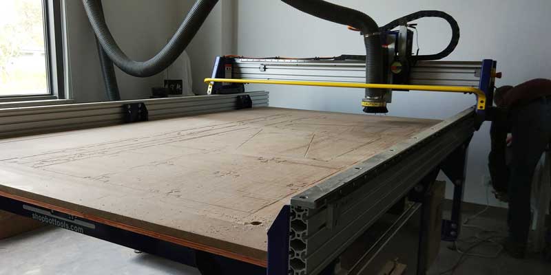
_MACHINE SETUP SUMMARY
Some important things to consider when setting up the CNC machine are:
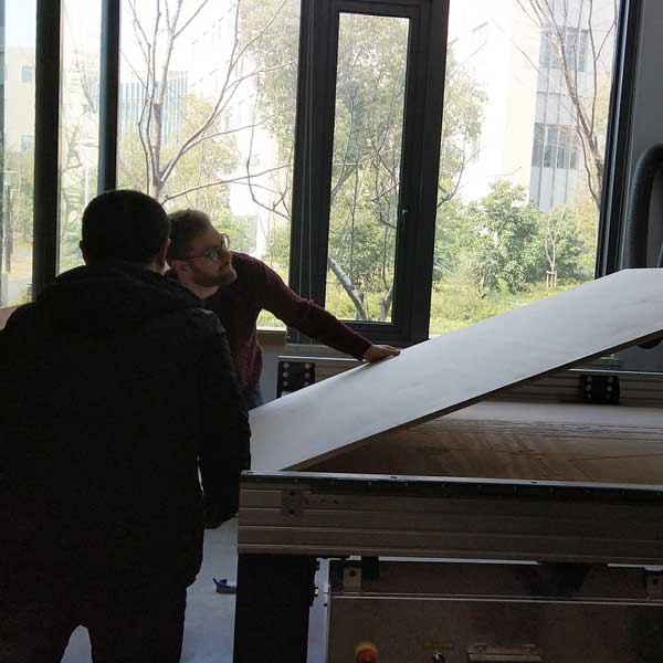
1_USE IN TWO: Recommended to use in two, never
alone.
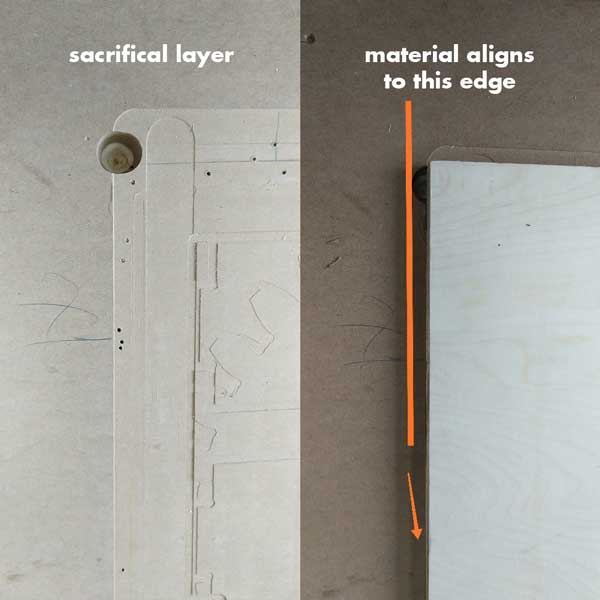
2_CLEAN THE SURFACE: When loading the wood sheet into
the bed make sure the surface has been cleaned, and there are no material leftovers (this could make
your sacrificial layer irregular).
3_LOADING THE MATERIAL SHEET: Place the wood sheet
among two people, don't do it by yourself.
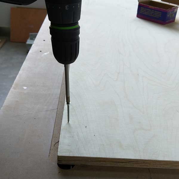
4_FIX THE SHEET INTO THE BASE: Once you load your
material in the sacrificial layer, fix it (either with clamps, or nails). This is super important not to
forget, you don't want your material to move or fly away.
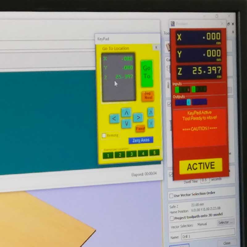
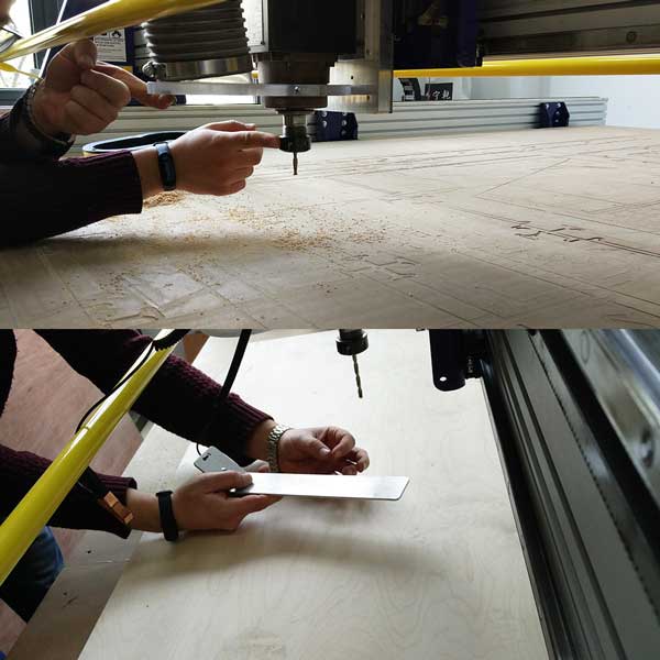
5_LOCATE Z AXIS: Using the special aluminum board and
clasp attached to the machine's spindle head. (remember to either locate the Z axis on the
sacrificial layer or your board, this depends on how you set up your file).
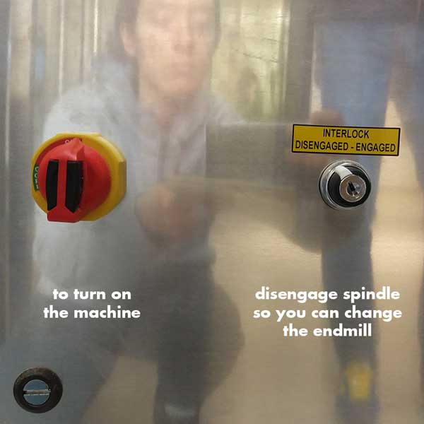
6_SET UP SPINDLE RPM: In our case we have to setup the
spindle RPM speed manually, so don't forget to set it up according to your file settings.
7_ADD TABS: Don't forget to add TABS into your model.
You don't want pieces flying away and hurting someone or yourself.
8_TURN ON Turn on the vacuum pipe to suck the material
while cutting.
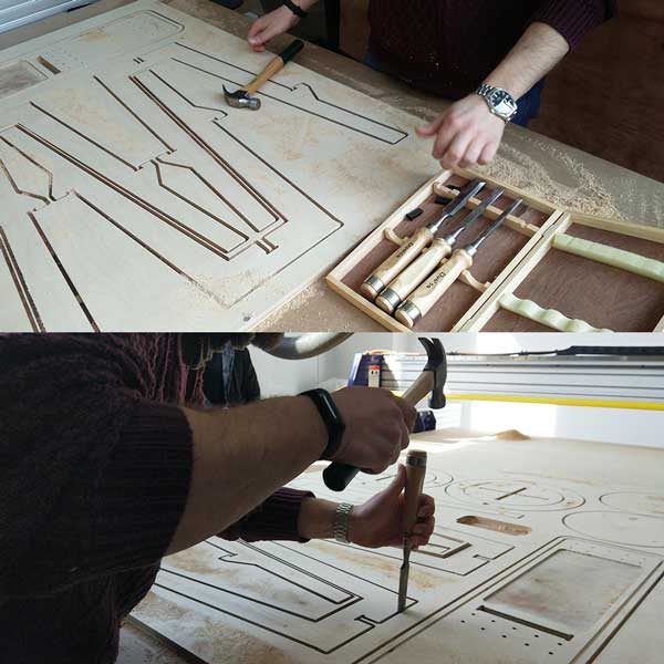
9_ONCE FINISHED: After your model is done cutting,
before removing it from the bed, use a cheasel to cut out the tabs. And don't forget to clean out the
machine bed once you are done.
There are more details to follow up, but this is just a short summary of essential things you shouldn't forget to do.
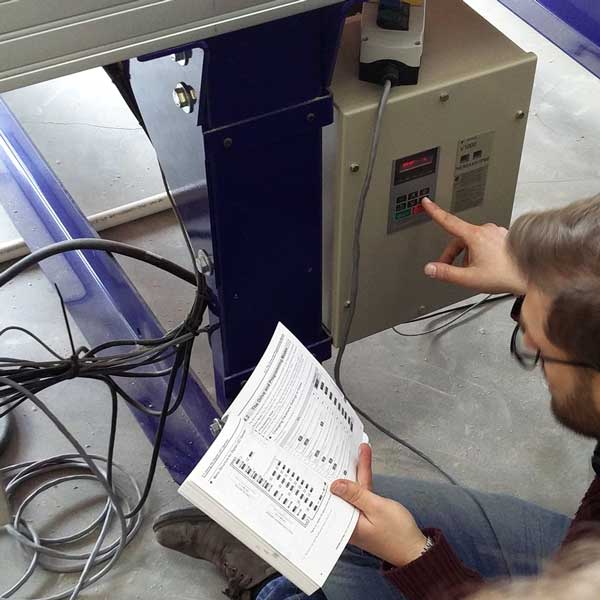
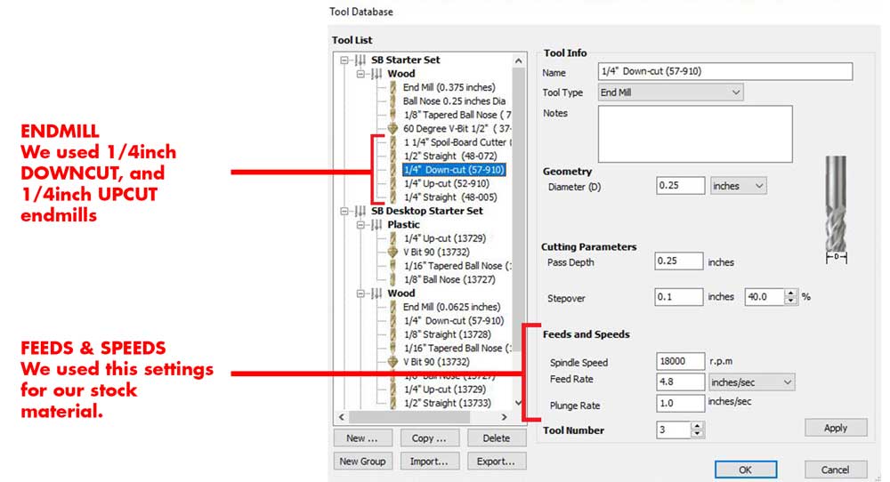
The material we will be using for this assignments is wood (soft plywood) of 14mm thick. So we did one module, and we ran several tests to check the speed and rates.
In this case for this material and its thickness, the optimal set up to use is 18 000 rmp, feed 4.8 and conventional cut.
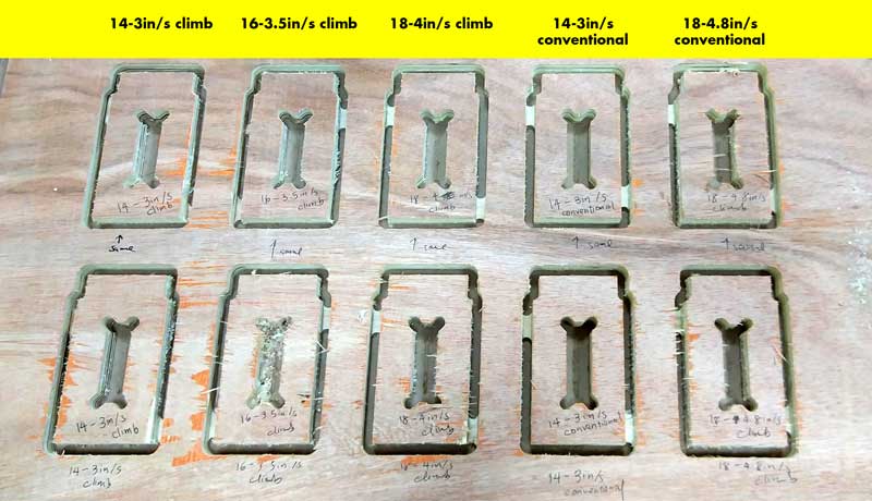
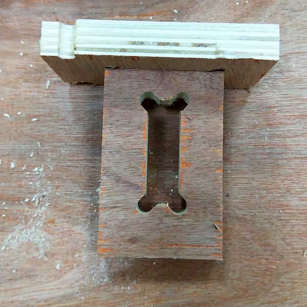
We checked as well how well each part fits into each one using exactly the same material thickness for
the slots.
And it came out the fitting worked out using 14mm on the slots (same as the material thickness).
Individual assignment
Ok, so for this week we have to BUILD SOMETHING BIG.
I wanted to make something innovative and cutting edge, but being the first time I do CNC milling in such a scale I thought of starting with something not very complex but specially being this my very first prototype, I decided to build something useful for my everyday life and not something that would end up in a corner.
_IDEA
I decided to design a stool-step-shoe rack, sounds weird, but let me explain you the
functionality.
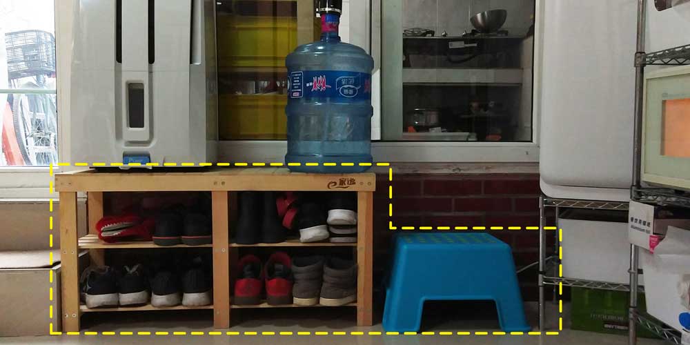
We live in an old chinese house, and the layout of the house makes zero sense, and to go into the
kitchen you have to climb a big step to go in (as the first floor is a bit below the ground), so this
step is crucial as every single day we have to setp in there to go in out to the kitchen and toilet
(forgot to mention that you have to cross the kitchen to go into the toilet).
And right now this is pretty much what we've been using, a plastic IKEA stool which is not nice at all,
but works ok.
And all that area (the shoes organizer and the stool that we use as a step), is what I will design:
_RESEARCH & INSPIRATION
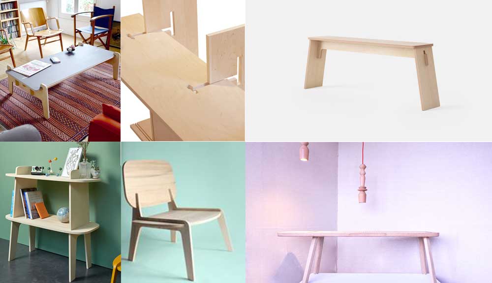
Before I started with the design, I did some research on furniture made with CNC machine, and I found out
a few cool and interesting brands you can check out:
1_OPENDESK
2_MAKEMAKE
3_ATFAB
4_Tim
Defleur
5_LOZI
6_INSTRUCTABLES they have a basic manual, worth
having a look if it's the first time you design a CNC model.
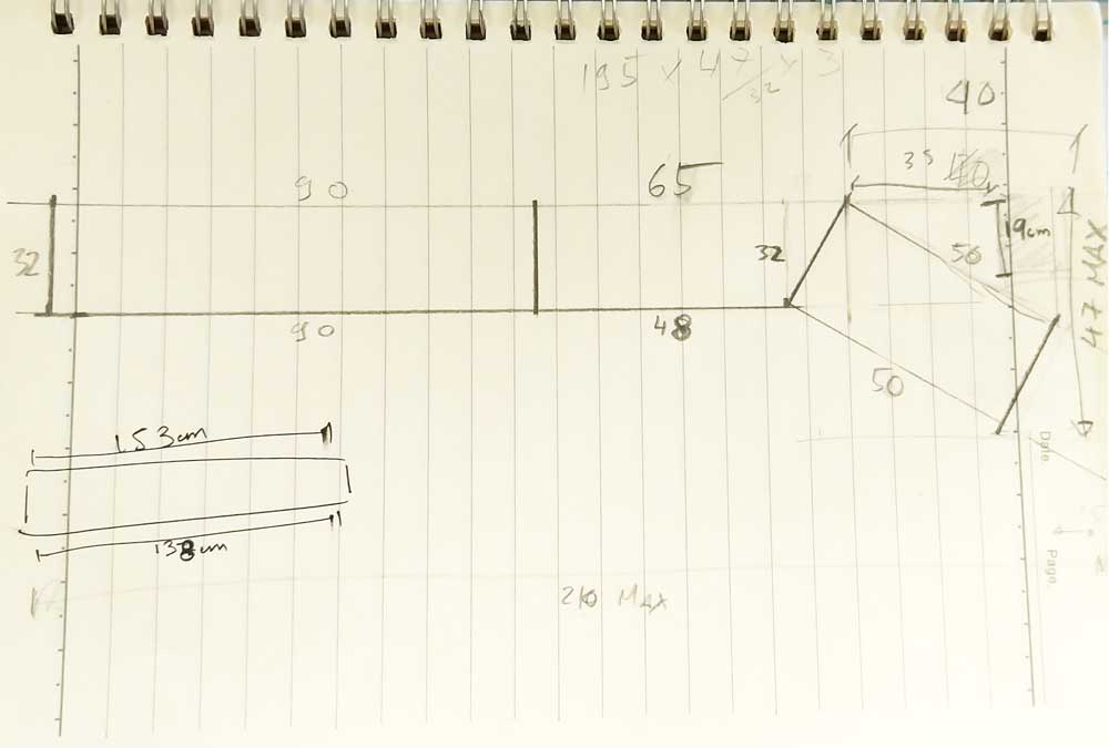
_TAKING MEASUREMENTS
Before I started to dream of a new shape, I did one of the most important parts TAKING MEASUREMENTS, because this will give me limitations on the design and will also tell me functions I shouldn't ommit when doing the design.
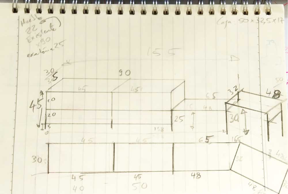
Having clear now the sizes and parts I needed to design, I started to think of the shape, assembly and
connections.
My first approach was to design a bench long enough so that I could put on top of it
also the AC machine, but you will see later why I had to change this.
This was the original diagram of what I was designing:
_BUILDING 2D & 3D MODEL
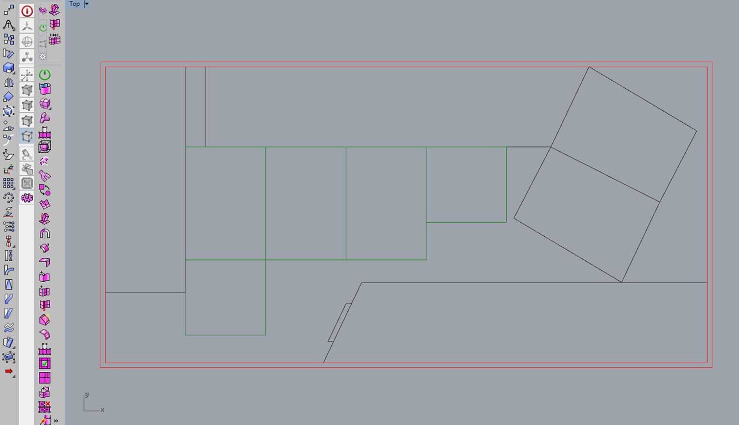
I used Rhinoceros 3D for this assignment. First I started by drawing the size of the material sheet we have available, which is 2440*1220mm, if my design was bigger then I better knew this from the beginning before starting the model.
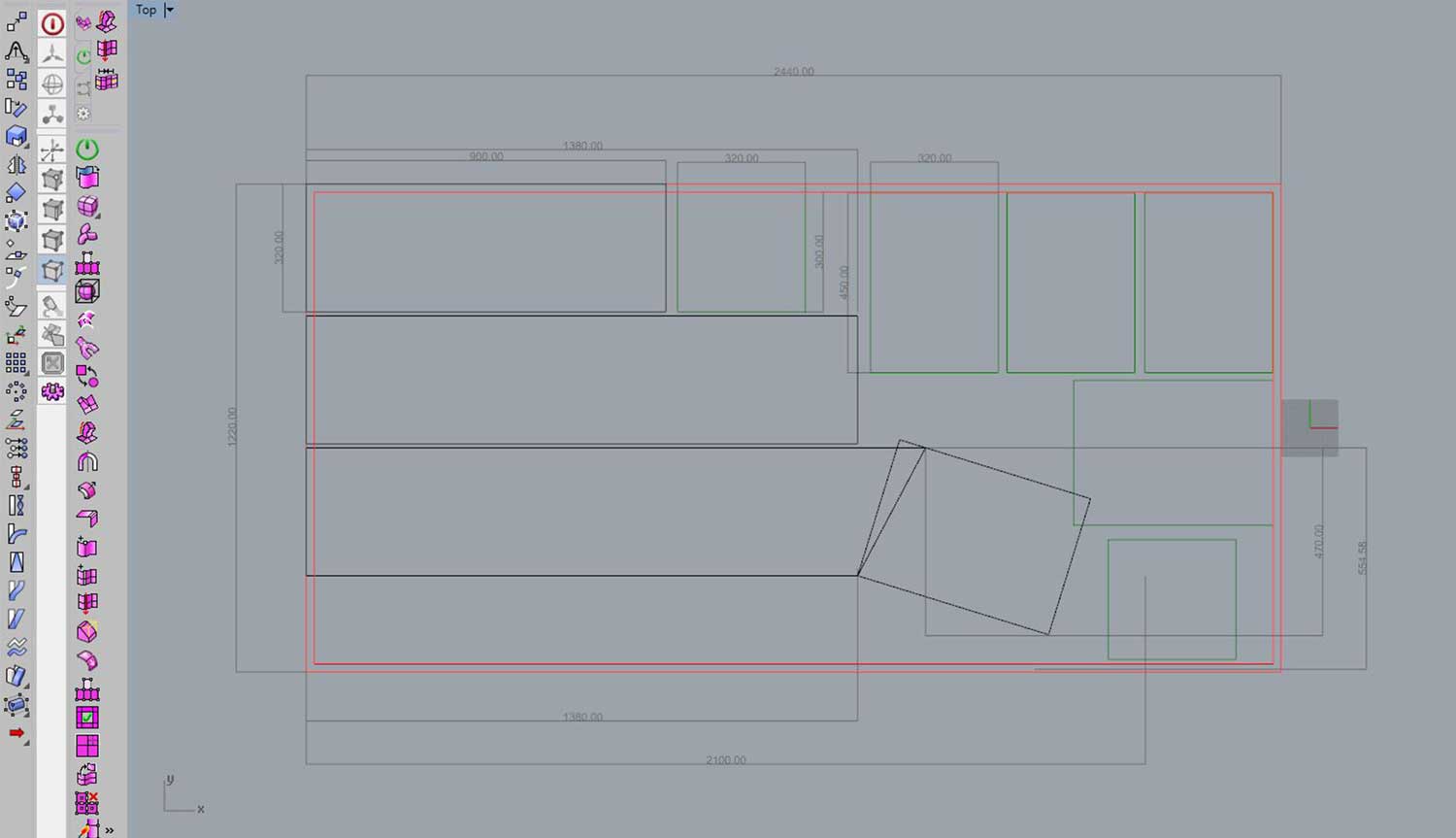
OnceI had clear my working area I drew the components general size, that I previously calculated I would be needing. In this case they are 9 modules.
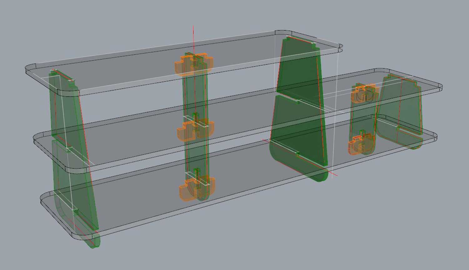
Now having these two parameters, I did a general 3D model to understand how it looked assembled the general shape:
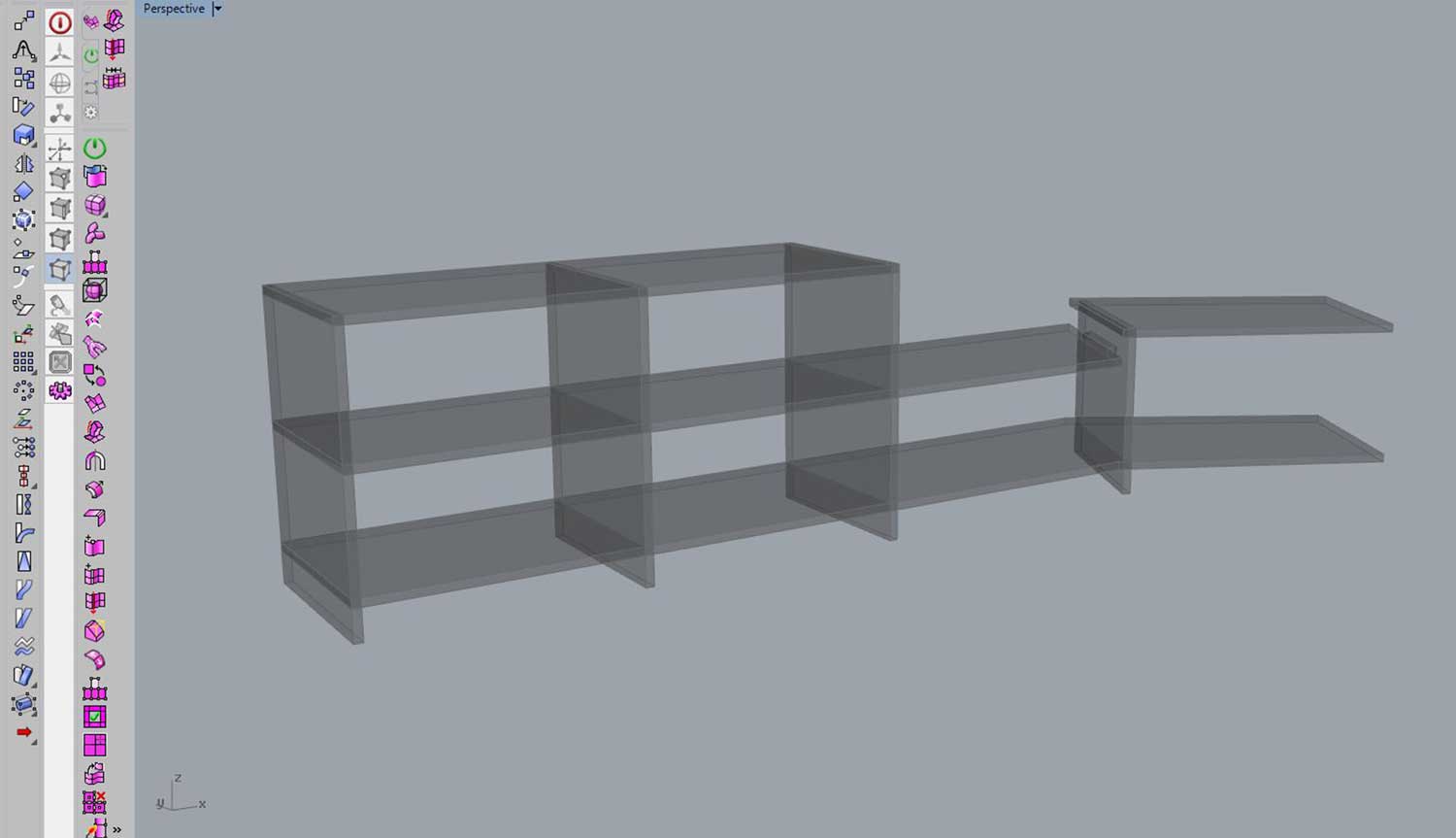
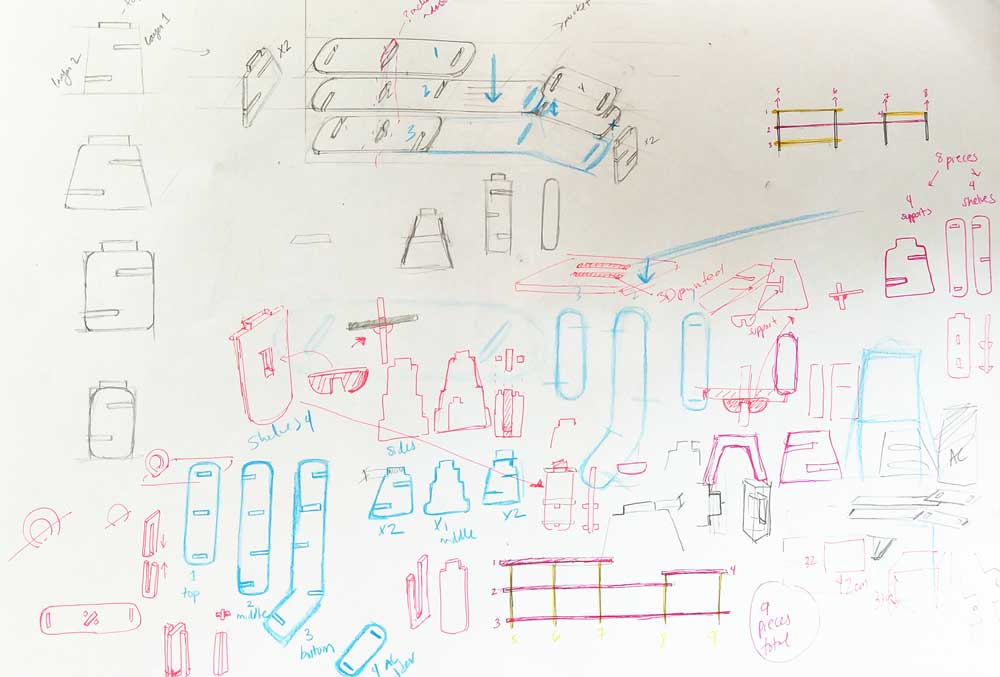
Ok, so from there I started to think and design each module:
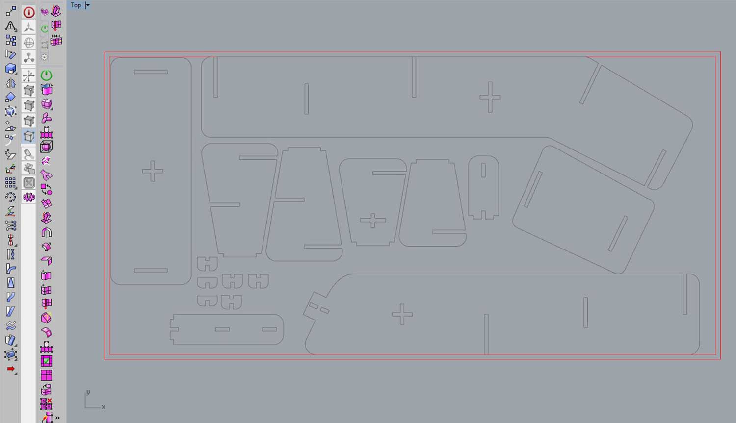
I then laid out the components flat, once again, to check if they would fit on my board.
After making sure they would fit, I scaled the model and exported as an Illustrator file as I would be
cutting a scaled prototype with the laser cutting machine.
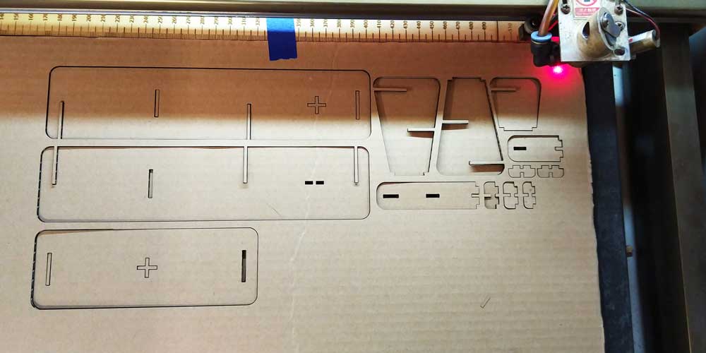
_LASER CUTTING PROTOTYPES
I was too naive to think the first model would work, I used plywood for the first model as it holds better than cardboard, but it was a bad idea because on the first model I immediately realized of a big issue, and it would have been better to use cardboard instead for the very first model, and then I could have switched into plywood.
When I was assembling the first model I realized, it would be really hard to assemble it when the model would be 1:1, I noticed it was particularly complicated the area of the AC holder, so I decided I would eliminate for now that part and just concentrate on the step and the shoe rack.
Change of plans on my model:
I removed that part and left the model a bit more simple.
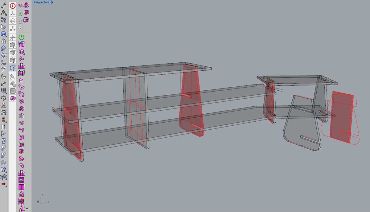
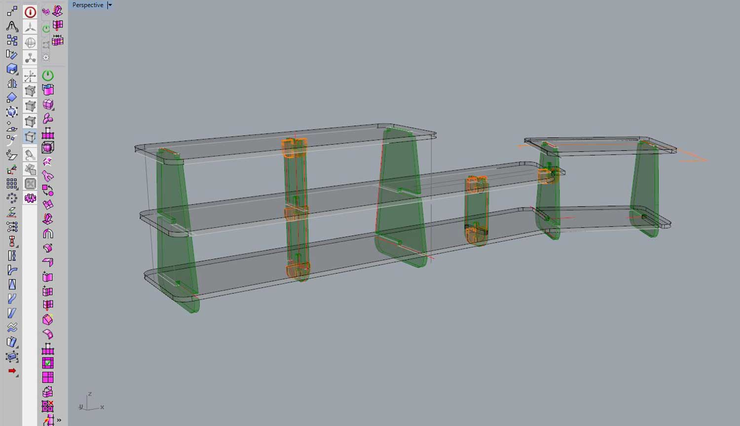
I added as well some parts to hold better
the vertical modules:
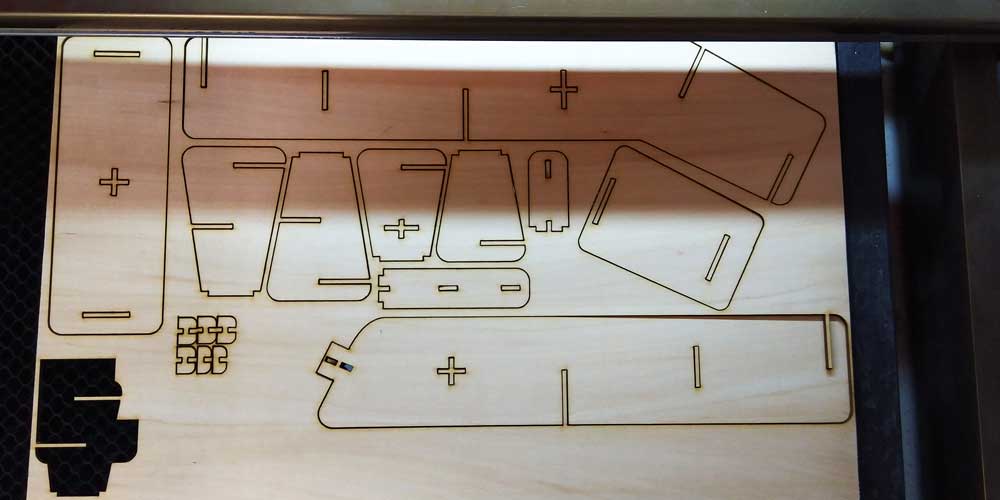
I did the same step as before, I laid all my modules flat, and prepared the file to laser cut it. But this time I first did a test in cardboard, and in the end I cut it out in plywood.
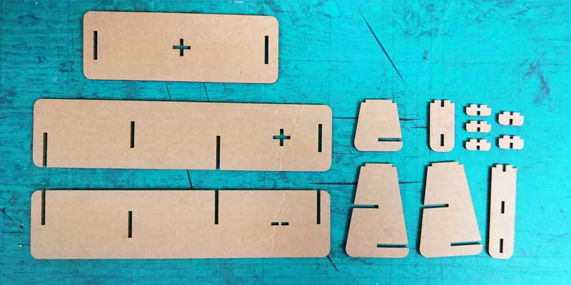
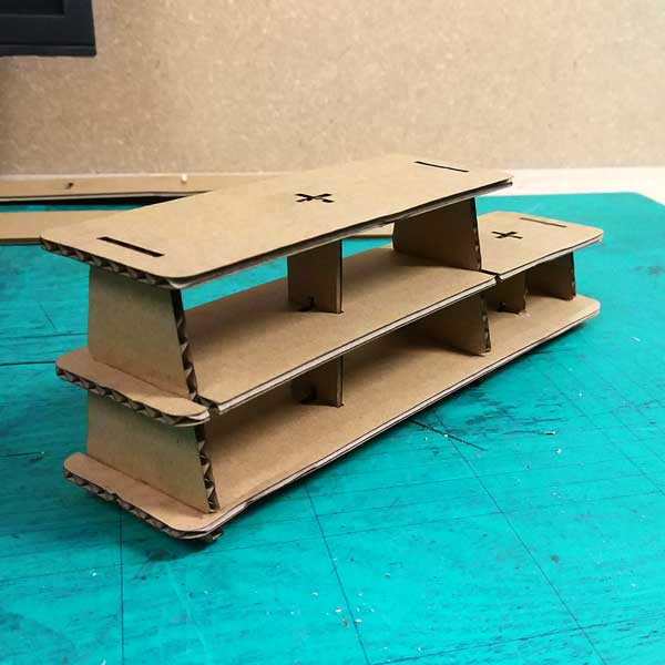
I did a few modifications on the joints, and then I did a test in plywood as cardboard was not the best holding the joints and the structure.
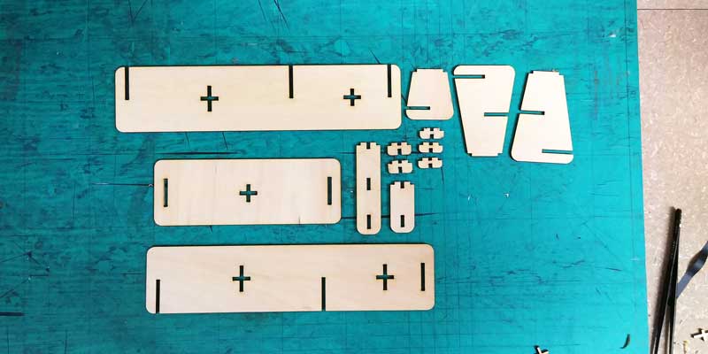
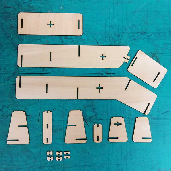
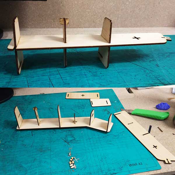
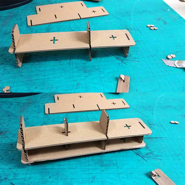
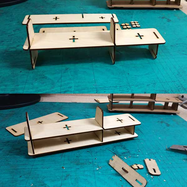
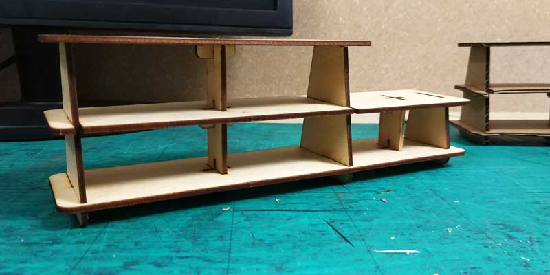
I also studied the best way to assemble the model because this will be very important once I cut the
scale 1:1 real model.
Below are the photos that shows how to assemble it in order.
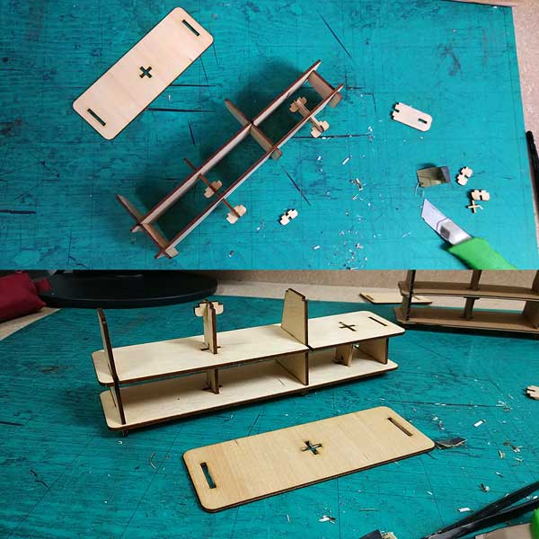
This is the final scaled model assembled, I am a bit worried if it will be capable to stand ones weight every time we step on it, but I thought this is a first prototype and I would like to see how it looks, test it and do a second iteration in another wood with all the improvements and/or modifications I will learn from the first prototype.
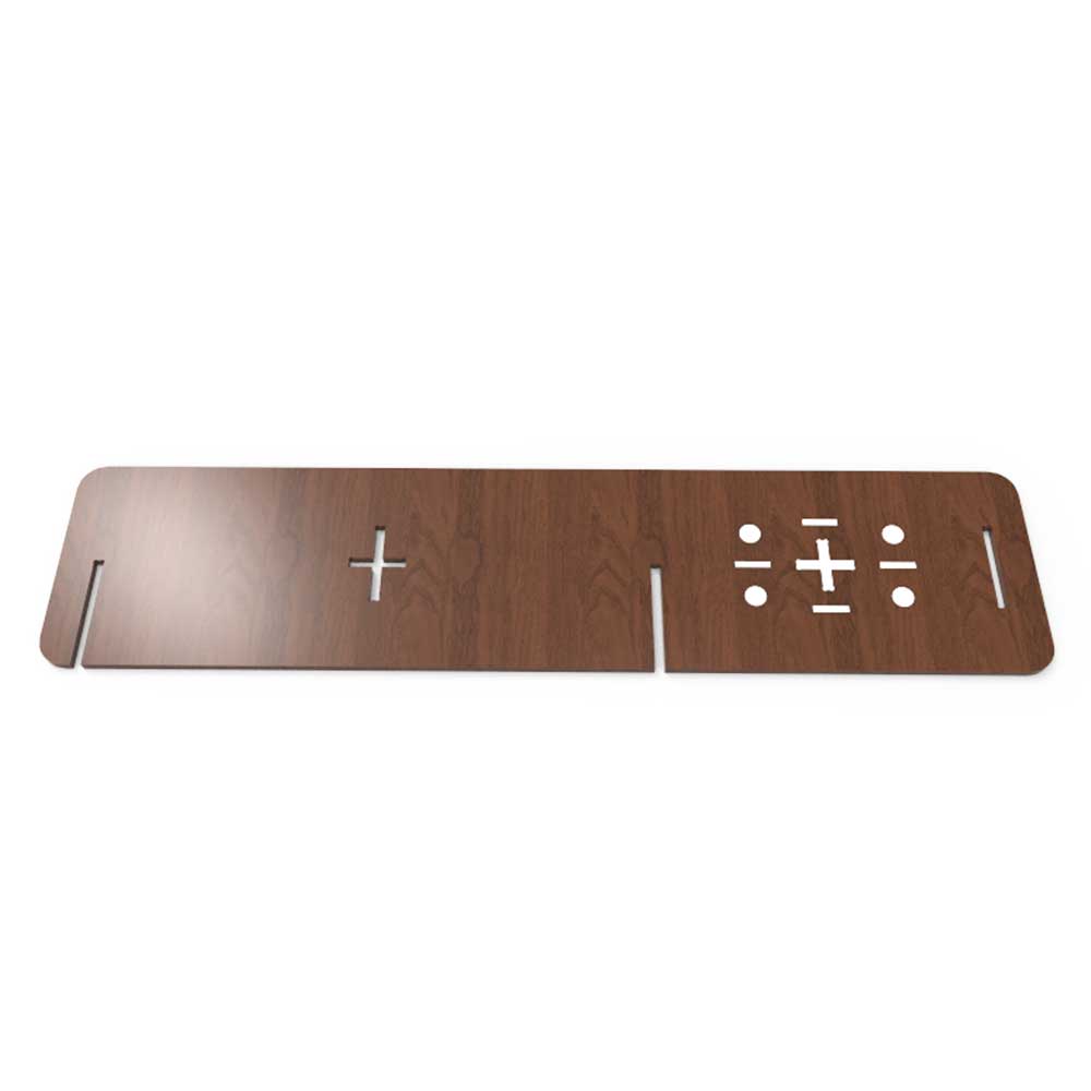
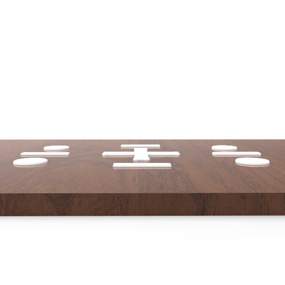
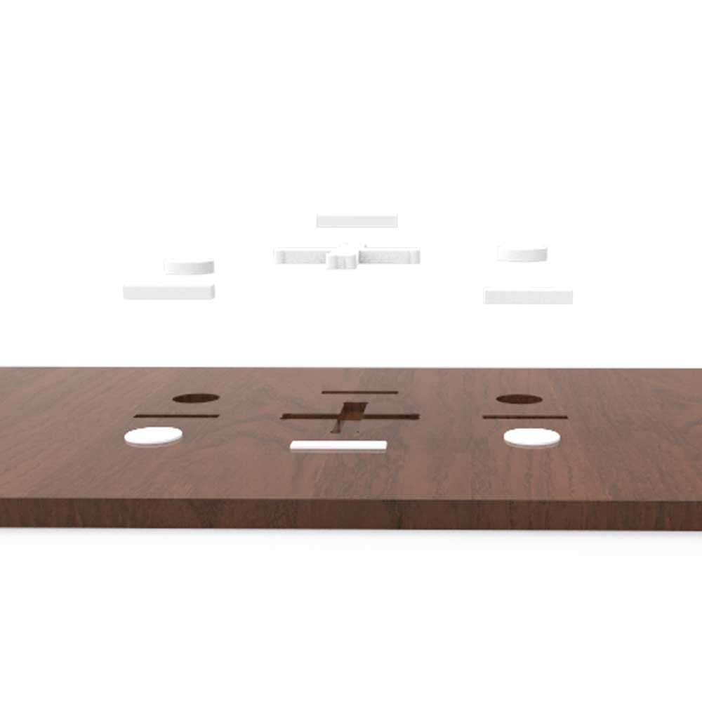
_EXTRA IDEAS
I would like to integrate some 3D printed parts into the model.
As the step needs to be anti-slippery, I thought of adding some 3D printed elements with some volume, in
the pockets of the wood that I will make.
Here is a rendered example of what I intend to do:
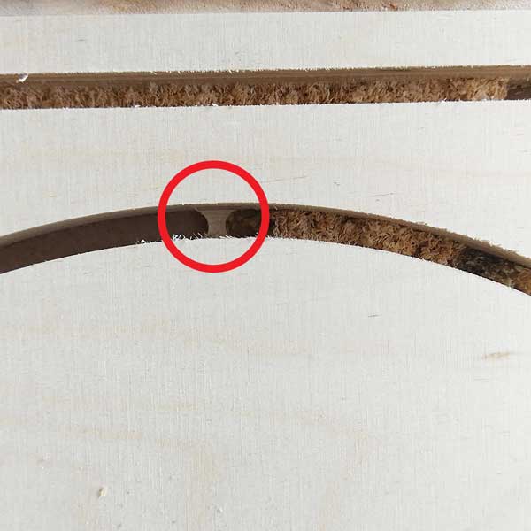
_INTERLOCKING TIPS
A good friend that works for OPENDESK, Danny Kuo, recommended me to use NODES for the interlocking slots.
Nodes are used to tighten the connections.
And depending on the material that you are using (the softer the bigger the node)the node varies.
In
my case as I am using a more dense wood, I am following the advice from this super useful article ABOUT NODES, using nodes of
0.2mm of width for 5mm-10mm of length.
So you understand better this is how a node looks like:
_VCARVE
Once my model was ready I exported it as DXF as I need to open it on a software where I will set up all
the tooling, and settings for the milling process.
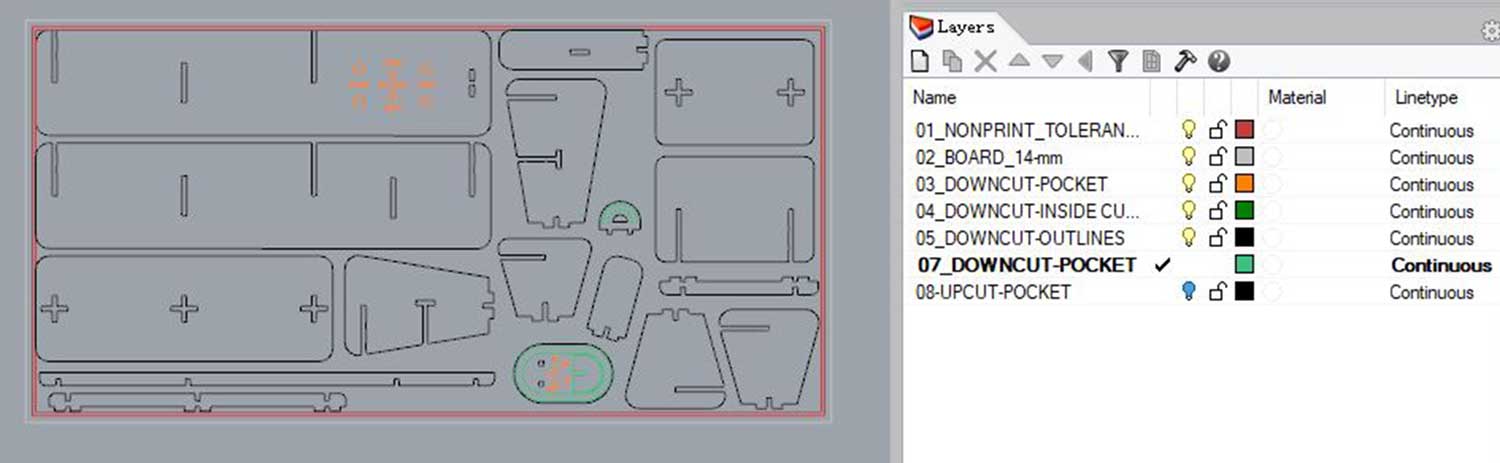
But before doing that is wise to label your layers and order them by task.
You can see how I did it below:
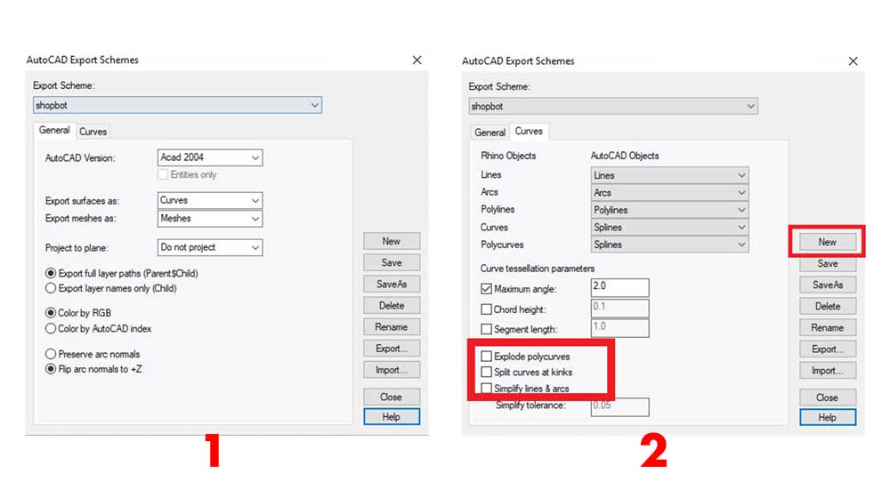
When exporting to DXF sometimes the polycurves are exploted, and this could give you errors in VCARVE,
what you could do in RHINOCEROS is to create a SHOPBOT DXF profile, so when you export as DXF you make
sure the polycurves are all closed.
You have to select the objects to export, go to EXPORT SELECTED> choose DXF > OPTIONS > EDIT SCHEMES,
and deselect the EXPLODE POLYCURVES option. Select the following (create a new profile):
After exporting I used VCARVE to set up the tasks.
In my case I had the following taks to do:
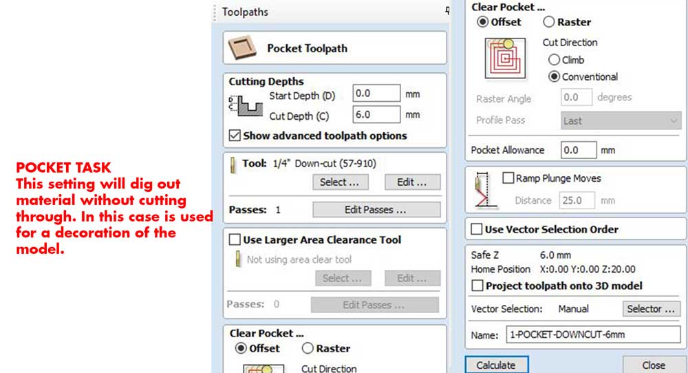
1_POCKETS: areas where you remove material without
going through all the material. You can decide how deep to go, but if you are using a DOWNCUT ENDMILL
make sure you don't go deeper than 6mm, if you want deeper cuts use an UPCUT endmill.
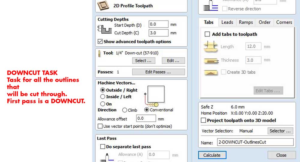
2_DOWNCUT: Run this task at first for all the
outlines that will be cut-out through.
At first you have to run a DOWNCUT task normally of 2mm-3mm deep. Why we do this? well the downcut
endmill leaves the edges of the material more clean as it makes the material to go down while cutting,
whereas an UPCUT pulls the material out and if you begin with an UPCUT you could leave the edges of the
material brittled. But be careful because the downcut is only to go deep as far as 2-3mm NOT TO CUT ALL
THE MATERIAL AT ONCE.
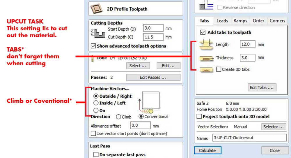
3_UPCUT: Run this task to do the second pass and cut
through the material.
This is a step by step on how to use VCARVE, using my model as an example.
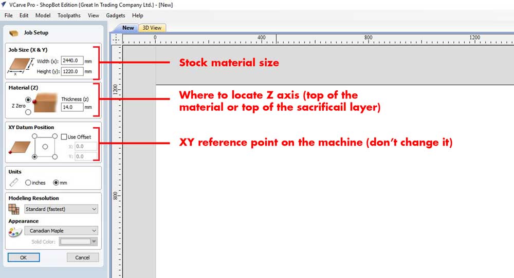
4_NEW FILE
Start by creating a new file, here you have to specify the size of your material. Normally there are standard size material sheets, in our case we will be using a sheet of 2440*1220mm, with a thickness of 14mm.
NOTE ABOUT STOCK MATERIAL THICKNESS:
An experienced colleague who works using CNC to create
furniture told me that there are two types of thickness, CONSISTENT and INCONSISTENT.
Consistent means, depending on the wood quality, that its fairly stable when measuring the 4 corners of
the sheet
and if all thicknesses are the same it means it has a consistent thickness.
Inconsistent means that
if you measure 4 corners and they are all quite different, for example from 17.6-18.4 mm, it means it is
very inconsistent the thickness.
You can find a way to solve the slotting:
1_If material is consistent, you can scale your complete drawing bigger OR smaller.
so now all the slots are 18mm, but if the material is 17.8mm, you can scale the complete drawing by -1%
and then it will probably all be prettty tight.
2_If the material is inconsistent you can use nodes, to lock the slots better, probably you will need a
hammer to assemble it.
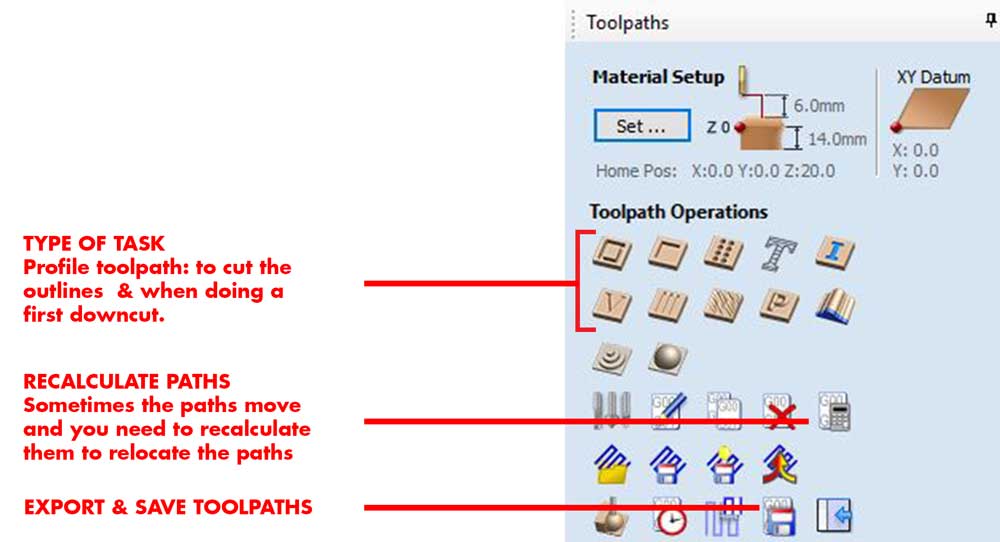
2_TASKS MENU
Select the group of vectors and open the TOOLPATHS menu, here you have to choose the type of task you are doing:
Here are three examples of 3 different tasks and its settings:
DOWNCUT TASK: you can decide if you begin from the top of the material or lower. You would choose
lower if there has been a previous DOWNCUT before and you want to add another layer of depth.
UPCUT TASK: when you are cutting through, and remember, as we are doing a downcut before your
START DEPTH is not 0, but the place where the previous job ended.
Remember to add TABS, this are small tabs that attach the piece you are cutting through from the stock
material. Always add them when doing a CUT, or else you will have material flying or getting stuck on
the endmill.
The climb and conventional are the direction how the endmill cuts from, choosing the correct one will
depend on the material, in our case we tested the material and saw CONVENTIONAL was the most suitable.
POCKET TASK: you can choose how deep to go but remember to change the settings of the TOOL you are using depending on the depth you want to reach.
Use CALCULATE option to see how the task will be done, this is useful to check your tasks and see if everything is correct.
Remember to always choose the correct ENDMILL, these are the ones we used for this prototype:
3_CHECK YOUR TASKS & ORDER YOUR LAYERS
Once you set up the tasks check in the 3D VIEW how it's looking the model, this will give you an
idea of the workflow.
It is wise to organize your layers by the type of ENDMILL you are using.
Always start from the pockets, then the downcuts and leave too the end the upcuts.
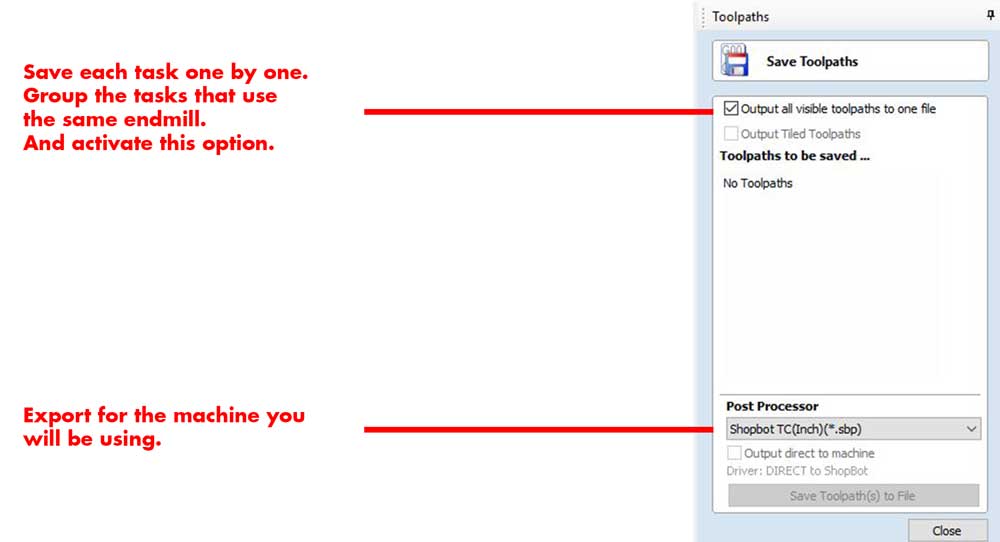
4_SAVE YOUR TOOLPATHS
Go to the TOOLPATHS menu and choose SAVE TOOLPATH, you will be prompted the following window:
_MILLING PROCESS & RESULTS
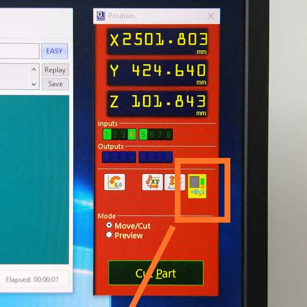
For full documentation on how to use the machine please see the group assignment above.
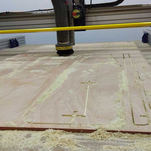
Here comes the fun part, using the machine!
Here are some photos of the milling process and of course there were some errors during the process:
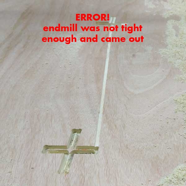
While doing the first task, the DOWNCUT, we noticed some weird noise, and it was the endmill that came
out of the collet, and you can see from the photo the scratch it made.
Fortunately my instructor noticed it on time and we stopped the task and we made sure the endmill was
well fixed, we also cleaned the collet before attaching the endmill once again.
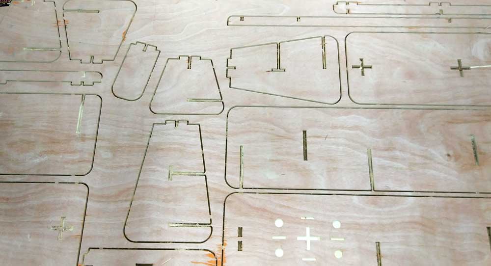
Here is my model after we finished the cutting part!!!
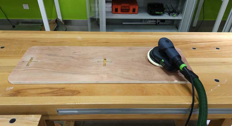
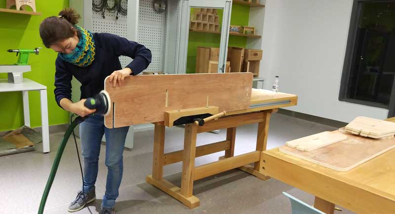
Once the parts were finished I did some cleaning on the wood, I cleaned the edges and checked if the
slots worked.
If they would have been too tight I would need to sand them to make them bigger, but in my case the
slots where a bit too big, this means my stock thickness was smaller than 14mm.
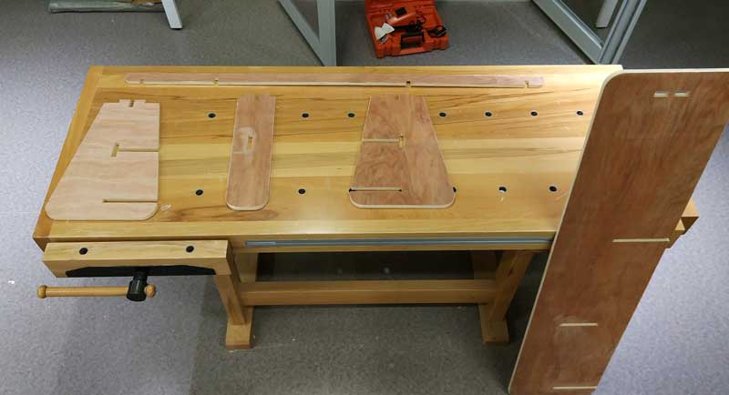
And........when assembling the parts, I noticed I made some mistakes...
=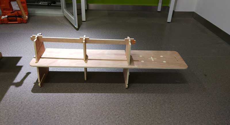
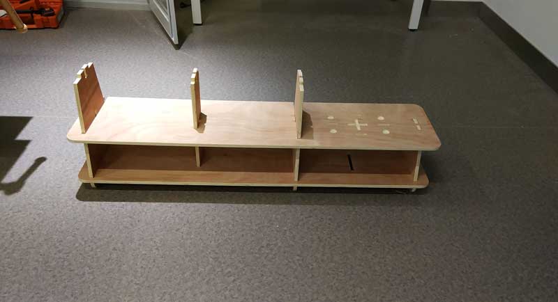
This was the final result! I did an extra small stool with the rest of the material:
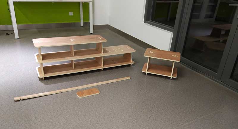
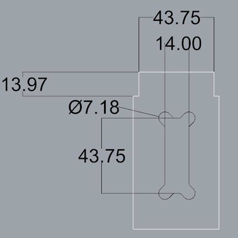
As you can see from the photo there are 2 parts left behind. What happened is that the supports I built the one that was supposed to be in the middle it was impossible to assemble the rack and add this long support.
To better explain the problem I made this diagram, and I added the solution to it:
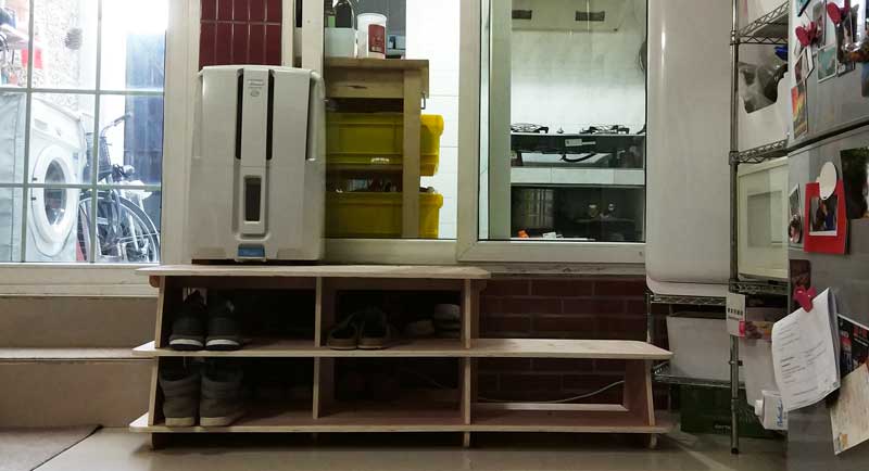
Here is a photo of the model assembled at home! I still need to fix it so we can use it =P
_CONCLUSIONS & IMPROVEMENTS
There are few other issues with the model, it slides a little bit on the horizontally, so I need to
understand how to improve that.
I also need to test the weight on the step and see how it works.
I brought the model home, but as it is missing the middle horizontal holder, unfortunately I couldn't step on it to try it, but I plan to improve this existing prototype and use it, after the usage I will be able to understant the things I should improve or modify.
I really enjoyed a lot this assignment. To be honest I was a bit frustrated at the beginning while doing
the design. I felt and still now I feel, that I could have done something more interesting, but while
doing the cutting process I realized that this is the first time I design furniture and I use the CNC
machine, and I this is a great first beginning and I enjoyed a lot the final process.
I feel very motivated to design more things and to use the CNC!
_DOWNLOAD FILES