For this weeks assignment I used my atmega 328p based board to send a signal over I2C to my attiny44 based board.
PROTOCOLS
There are a few protocols, which can be used to commincate between boards. I will explan a few of them.
UART
Uart stands for Universal Asynchronous Reception and Transmission and is a simple communication protocol, which uses the RX and TX pins to communicate. It allows the user to communicate with the computer over usb also.
I2C
I2C stands for inter-integrated-circuit and is specially designed for microcontrollers. It is more popular to communicate with modules and sensors, making it more useful with projects where you have to a lot of parts working together. You can set master boards which send information and slaves which will read the information.
SPI
SPI stands for Serial Peripheral Interface, it's nearly the same as I2C with the difference that you can only have one master and up to four slaves working together, which makes it unusable for very complex projects. SPI is due his simple protocol very fast, even faster then I2C and is used where speed matters like for example in sd cards.
I decided to use I2C, because I wanted to leave me a door open to attach more peripherals as masters, and also if somenone wants to replicate my board they dont have to rely on software serial.
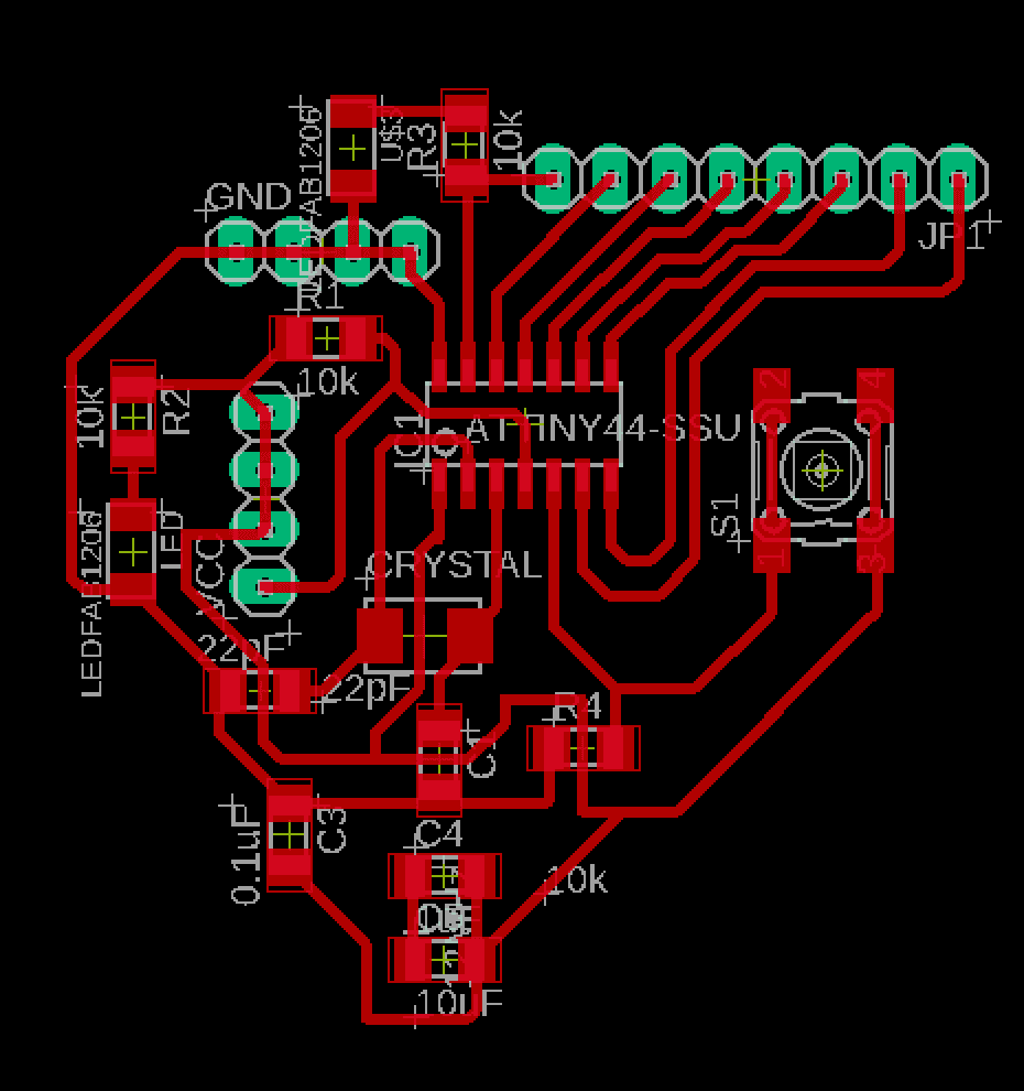
BOARD DESIGN
The first board and also the master has a atmega 328p chipset and it will send a boolean using the Wire.h library
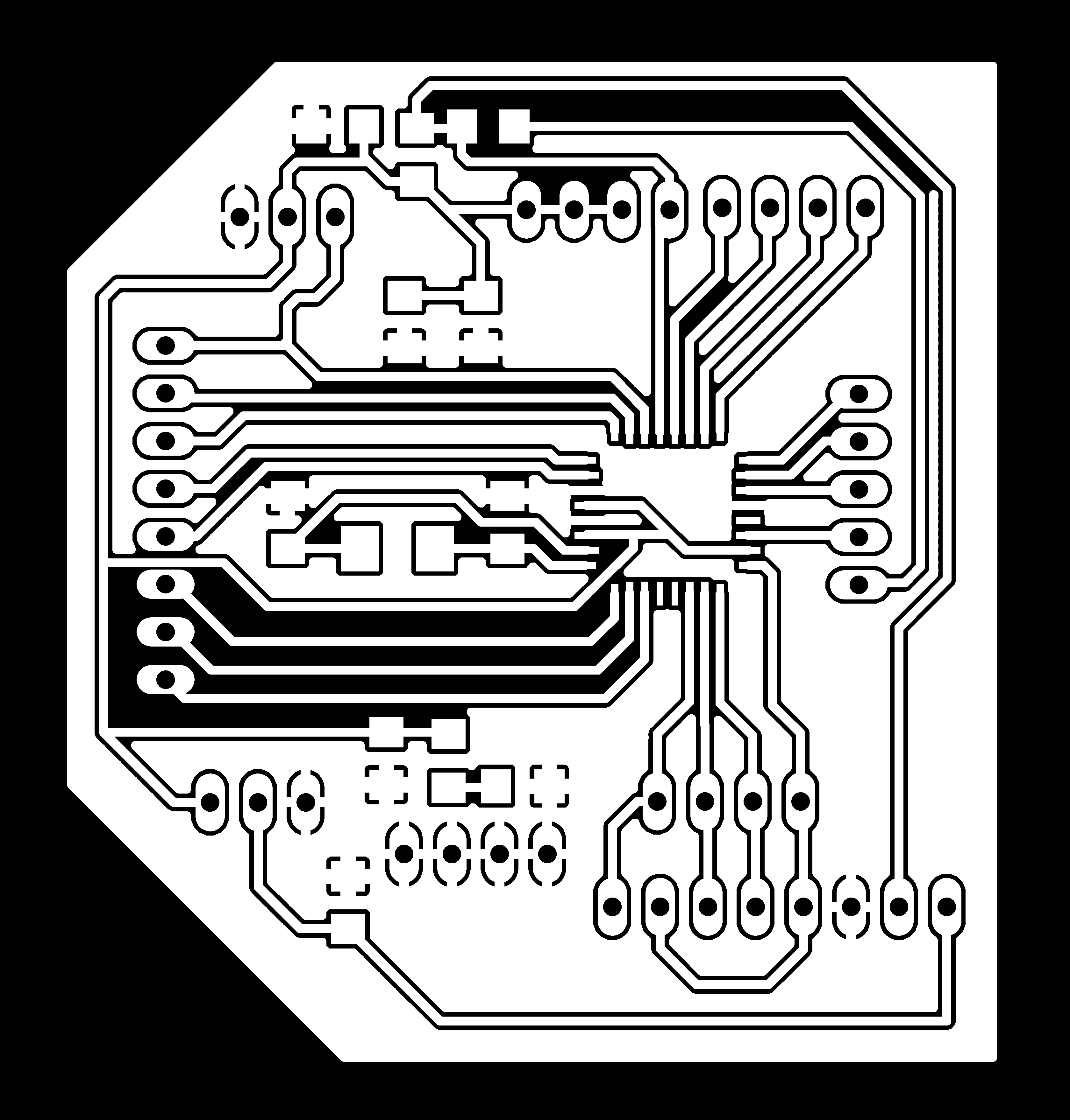
The second board and also the slave has a attiny44 chipset and it will receive the data from the master to light up an led.
#include                //include the wire library
#define SLAVE_ADDR 0x26         //defining the adress of the slave, the slave must have the same adress
bool auth=true;                 //setting "auth" to true
void setup() {

Wire.begin();                   //begin the wire conection
}

void loop() {
  // put your main code here, to run repeatedly:
  Wire.beginTransmission(SLAVE_ADDR);       //start the transmission to the adress we set in the beginning
  Wire.write(true);                         //writing true to turn on the led on the slave board
  auth = Wire.endTransmission();            //end the transmission
}
The master should be all set, but now we have to programm the slave so it can receive the bool properly.
			#include           //include tinywireS library, to use with attiny chipset
#define SLAVE_ADDR 0x26         //define the adress of the slave


bool auth=false;

void setup() {
  TinyWireS.begin(SLAVE_ADDR);      //begin wire using the adress we set in the beginning
  pinMode(0, OUTPUT);               //set pin 0 as output pin
  auth = TinyWireS.available();     //check if data from master is available
  auth = TinyWireS.receive();       //set our boolean to the data we have received

}

void loop() {

  if(auth == true){
    digitalWrite(0, HIGH);         //turn on led when the boolean is true;
  }

}
When data is received the led will turn on, otherwise it will stay off. The only thing left to do is the wiring.
WIRING
To send and receive data over I2C, I had to connect the scl and sda pins of both boards together. The atmega has exposed scl and sda pins on pin 28 and 27. Because thse attiny doesn't have these pins we will simply connect it through the programming pins sck and mosi
SCL (pin 28) -> SCK (pin 9)
SDA (pin 27) -> MOSI (pin 7)
When everything is connected properly, the led on the slave board should light up. To use the attiny for master slave communication you must use the tinywireS library which is modified for attiny44/84, simply follow this link to download the library.
DEMONSTRATION
YOUTUBE LINK
I have used the arduino uno as an power supply for both boards..