.png)
Hi! Welcome to Week 8
This week’s assignment was to make something big!
.png)
This week’s assignment was to make something big!
I have been thinking about what I want to make in this week almost since I started the FabAcademy. This week gives a large degree of freedom in designing, but after having my mind blocked for around 6 days, I realized that having less constrains kind of makes it harder. I lost a lot of time while trying to make something original and unique, but after designing it I was pleased with the results.
So, I decided to make a table/chair/stairs stand, that can be used in several ways (I’m a fan of smart furniture). This piece consists of a vertical and a horizontal wooden pieces, connected together through a living hinge, with a hole on the horizontal side to slide around a fixed stand. These pieces will come in different sizes so that the stand will have 5 layers. Also, the body can be arranged to take a small space, in case I wanted to put it away or just not use it. This is a sketch of how I imagine it will be.
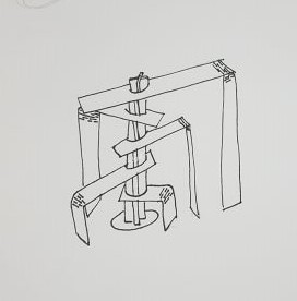
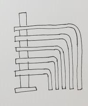
I started designing the “thing” (I need to come up with a name for it) on Fusion360. In my head, I turned the edges and all to flat surfaces, and worked my way from there. That was relatively easy as it was basically drawing straight lines, arcs, offsets and mirrors.
A new thing I did this week is using "dogbones". They are little circular holes added where I want a right angle cut. The reason we add these is that when we what to interlock between 2 pieces where one of them a right angle cut, the tool diameter restricts us on not having the required angle, and so the pieces won't fully interlock. The following image shows how the cutting tool would pass if there was no dogbones:
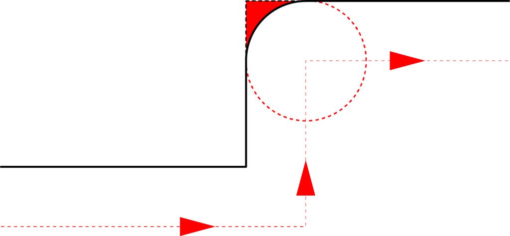
And so that's why we need them. I drew 2 rectangles on fusion, dimensions are 2400*1200 mm which are the dimensions on the wood plate I'm using, and I placed all parts within them. This process of laying all components they way they would fit in the plate is called nesting. I then extruded the parts, and to get the outline in 2d, I selected the bodies I wanted to outline, then head to sketch, project, project, and a pink outline is generated. form the menu on the left, I saved the generated sketch as DXF. here are the files of the and the first board and the second board, and you can also download the original file.
Now to prepare the job, I started using vCarve, which was my first time using it. When I added a new file, I got this window, where I inserted the dimensions of the plywood board I’m using, but I added 4 and 2 cms allowance, so that when the cutting tool is working it won’t hit any fixing nails that might damage the head, also, I sat the Datum Position, which is where the spindle is in accordance to the XY axis.
Then, I selected the parts that I want to be cut from the inside together, as well as the parts that I want to be cut from outside the traces and on them. This step is called preparing jobs. every group of cuts that I want on the same side are chosen together, and the tool path is chosen for them (inside, outside, on the trace). With inside, I mean that I want the cutting tool to cut from the inside of the traces, this is used with the cuts in the bodies. With outside, I cut the outer cuts of the bodies, and on the traces, I cut the living hinges. when I'm cutting the inside or the outside, the program take the tool diameter into conserations, and so the resulting pieces had the same diemnsions in the design. The living hinge traces were closer to each other that the tool diameter, so if I tried to cut it using inside cut, the proram would neglect it and won't cut it. Another thing I used was to use climb cutting instead of conventional. The main difference between climb and conventional cutting is how the cutter bites into the material. A conventional cut deflects the bit towards the cut and a climb cut pushes the bit away. Climb cutting is often preferred when using a CNC router, as it causes less grain tearing or “tearout.” However, climb cutting can be dangerous on a noncomputer controlled router, as the piece may be hard to control by hand and may “walk away.”
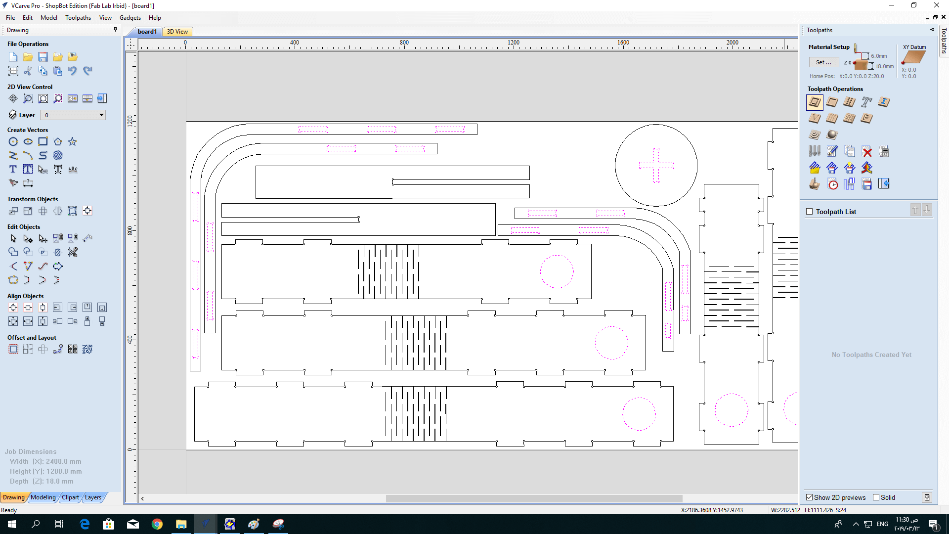
Next, I added the information of the cutting tool and other settings, I used the straight cutting tool so that the rear part of the pieces would have the same dimensions as the upper one. The pass depth is how low I want to cutting tool to go in the plate with each pass, the reason we add several passes with low depths is to get better finishing of the piece, and to lower the possibility of breaking the tool. It would also be good to know the following terms:
* Spindle Speed: rotational speed of the cutting tool in revolutions per min.
* Feed Rate: Surface speed at the center of the rotating tool.
* Plunge Rate: the distance in the z direction per pass that a cutting tool is plunged into the material.
I was adiveced by the CNc supervisor to use the default settings, but of course they can be calculated. you can get to know more abou their calculations from here.
here, I had a problem, as the distance between the hinges frame line was smaller than the diameter of the cutting tool, and since I sat it to be cut from outside, it didn't show in the simulation and it just skipped it. To solve this, I drew new lines in the middle of the original ones, and then chose to cut them on the line.
Another thing I added was tabs. Tabs are little links between the board and the piece I'm cutting it from. they are used to keep the cut pieces in place, and it could be easily removed later with a hammer.
After finishing with program, I saved the vCarve file, placed the wood board on the bed and fixed it using nails.
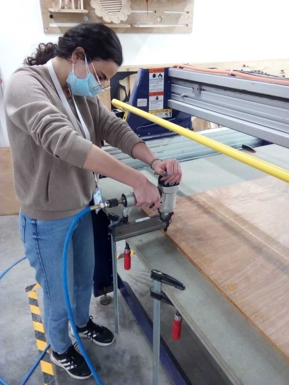
Now, I proceeded to set the XYZ axis. For the X and Y axis, it was straight forward, as I moved the spindle from the ShopBot panel on the computer. As for the Z axis, I placed the calibration plate beneath the cutting tool on the board, and the alligator clip on the cutting tool, and then from the computer, the head automatically calibrated the Z access by lowering down till it touched the plate.
I then ran the program. In the beginning, it went well, but after around 15 minutes, I stopped hearing the cutting noise from the machine that was when it started. I stopped the machine and checked and found the cutting tool to have broken, I changed it and proceeded with the cutting process.
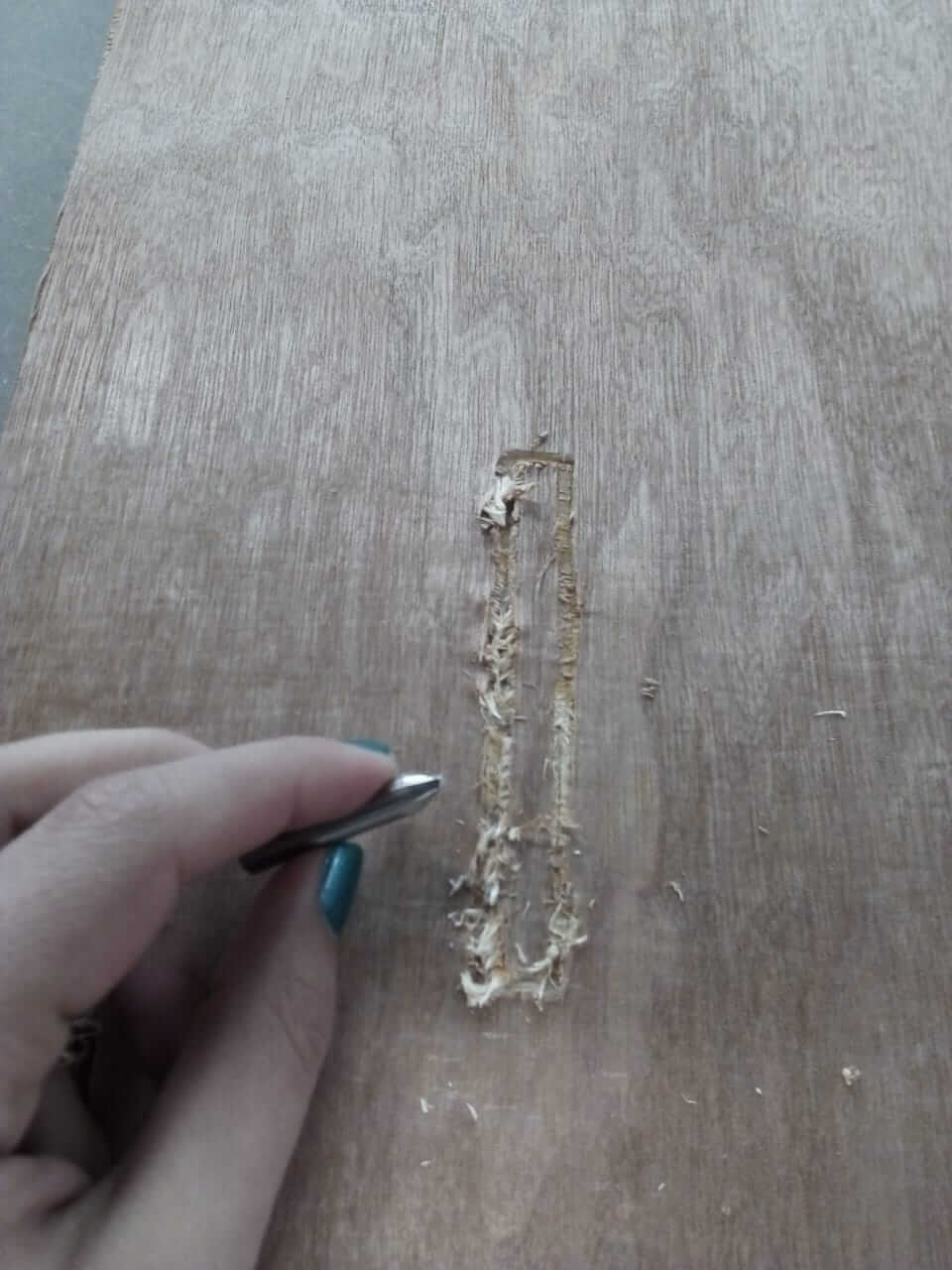
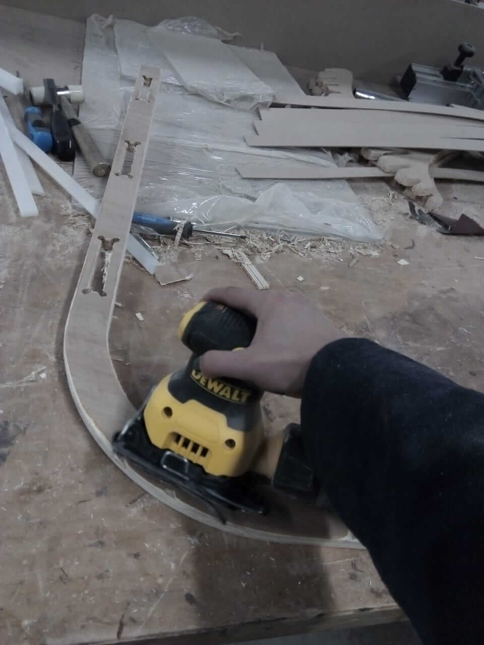
when the board finished, I removed it and checked it. I found that some holes weren't cut all the way through, which was probably because the board was concaved, but I completed the holes using a file, and then sanded the parts for a better finishing.
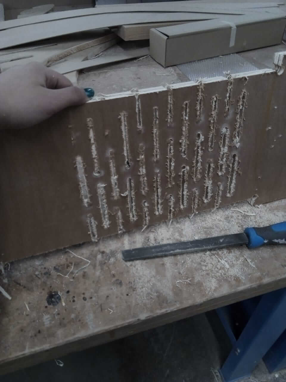
Here comes the fun part :D Although the living hinge didn't turn out that way I wanted and I ended up cutting it, I added the pieces together and assembled the body, and here you can get a better understanding of the "thing" I was trying to describe:


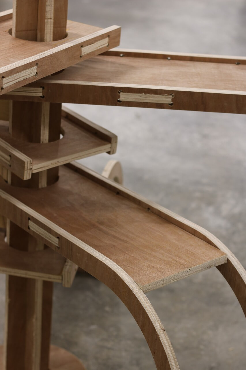
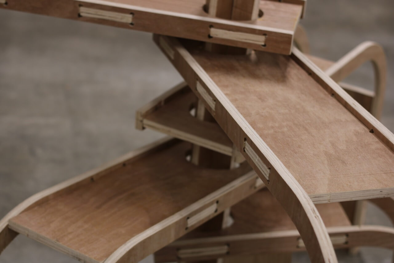
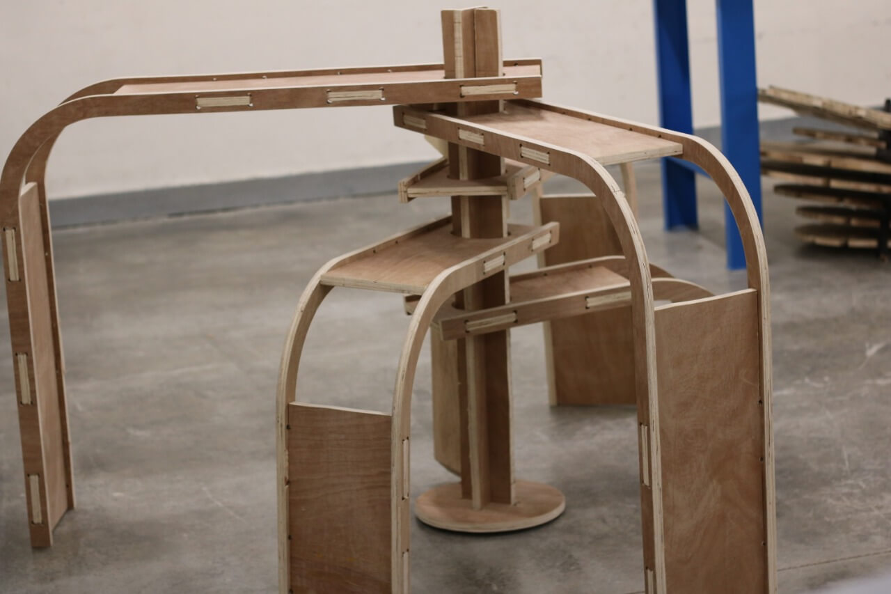
And here is an example of how it can be used. Of course, one can use it in any other way they would like, a table, chair, ladder...etc.
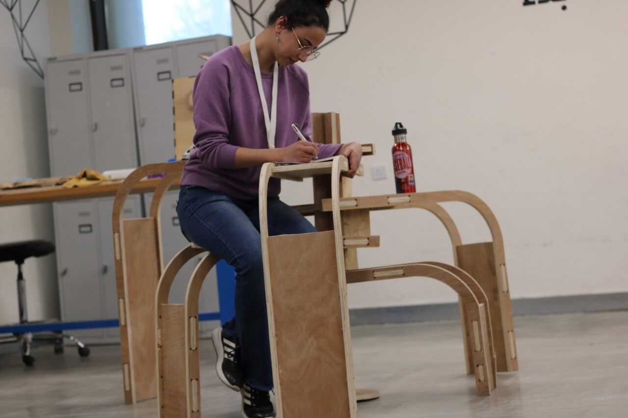
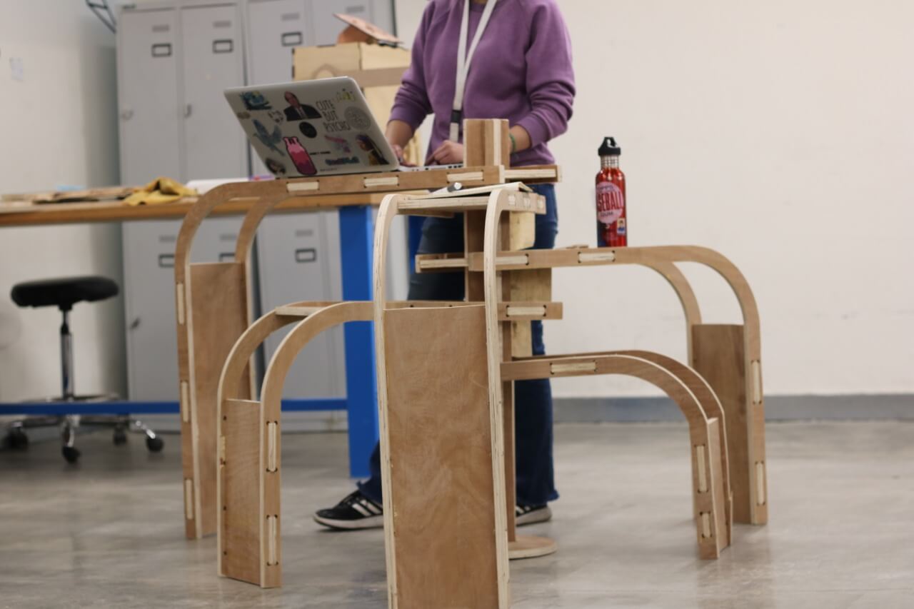
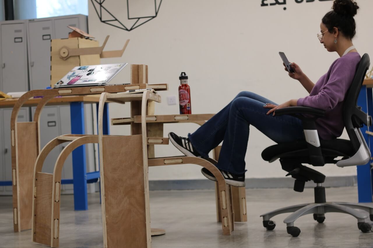
UPDATE!
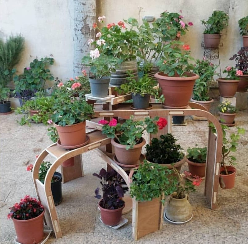
Although the purpoe of this design was to serve as a multi-purpose unit, my mom decided that it would be perfect to be used in the garden with flowers and so, this is the design in action:
