.png)
Hi! Welcome to Week 4
This week’s individual assignment was to cut something on the vinylcutter, and design, lasercut, and document a parametric press-fit construction kit while accounting for the lasercutter kerf.
.png)
This week’s individual assignment was to cut something on the vinylcutter, and design, lasercut, and document a parametric press-fit construction kit while accounting for the lasercutter kerf.
Vinylcutter:
I have previously used the vinyl cutter to print stickers. This week, I started by collecting the images I will be printing. To make things easier, I tried to find PNG images of what I wanted. Next, I used Corel draw to arrange them. I traced the outer lines mostly as high quality images and deleted the original ones. Then selected each object separately, wen to object, shaping, boundary, and then right clicked on the red color in order to set these lines later as cutting lines. I should note that the thickness for a cutting line should be added as hairline.

Lastly, I saved the file as pdf which you can download from
here.
I opened the Roland VersaWorks Dual, and added the pdf file
and used this set up:
and saved the file. Before printing I wanted to change the printed stickers material from white to transparent and that’s how I did it:

I lifted the upper arm, loosened the lower bolt from both sides and removed the white roll and added the transparent roll. I headed back to the computer and gave the print order.

I found the first print to be huge in size and the stickers wouldn’t fit my laptop, so I scaled the size to 30% and printed again.
The print size of the second trial turned out to be really, REALLY small in comparison to the laptop.

Instead of printing again, I chose the size I preferred from each sticker and put it on my laptop.

Laser:
This week I designed and cut different geometric shapes with press fit joint in them. These pieces can be collected into different shapes which I will show few of them later. I used Coreldraw to design the basic shapes.

And these are the final shapes:
Then I tested the part on 3mm thick acrylic transparent sheet. I used the following settings in the first trial:
When the laser finished, the pieces we’re cut all the way through.

I repeated the cutting process again but changed the variables such as:
Again, they cut didn’t reach the bottom of the board. These are the variable of the trial that worked and gave me the results I want:
I tried to fit the pieces together and they fit perfectly and I could move on to make larger numbers.

But first, let’s talk a bit about parametric design. Parametric design means to design something, but instead of adding dimensions as sole numbers, we add them as different defined parameters, and we also add here the relationships between the different segments in the design. When we finish designing this way, each sketch is defined in terms of what is X to Y, this way, If I changed X, Y will change also accordingly, and although distortion happens when we change one of our parameters, the ratio and relationships between the segments, in other words, we change the size but maintain the shape. To do that, each segment must be added as a parameter in dimension, and a relation to another one (2 lines are parallel, 2 lines are perpendicular, line X starts at the middle of Y, and so on ...).
The way to use parameters is as follows:
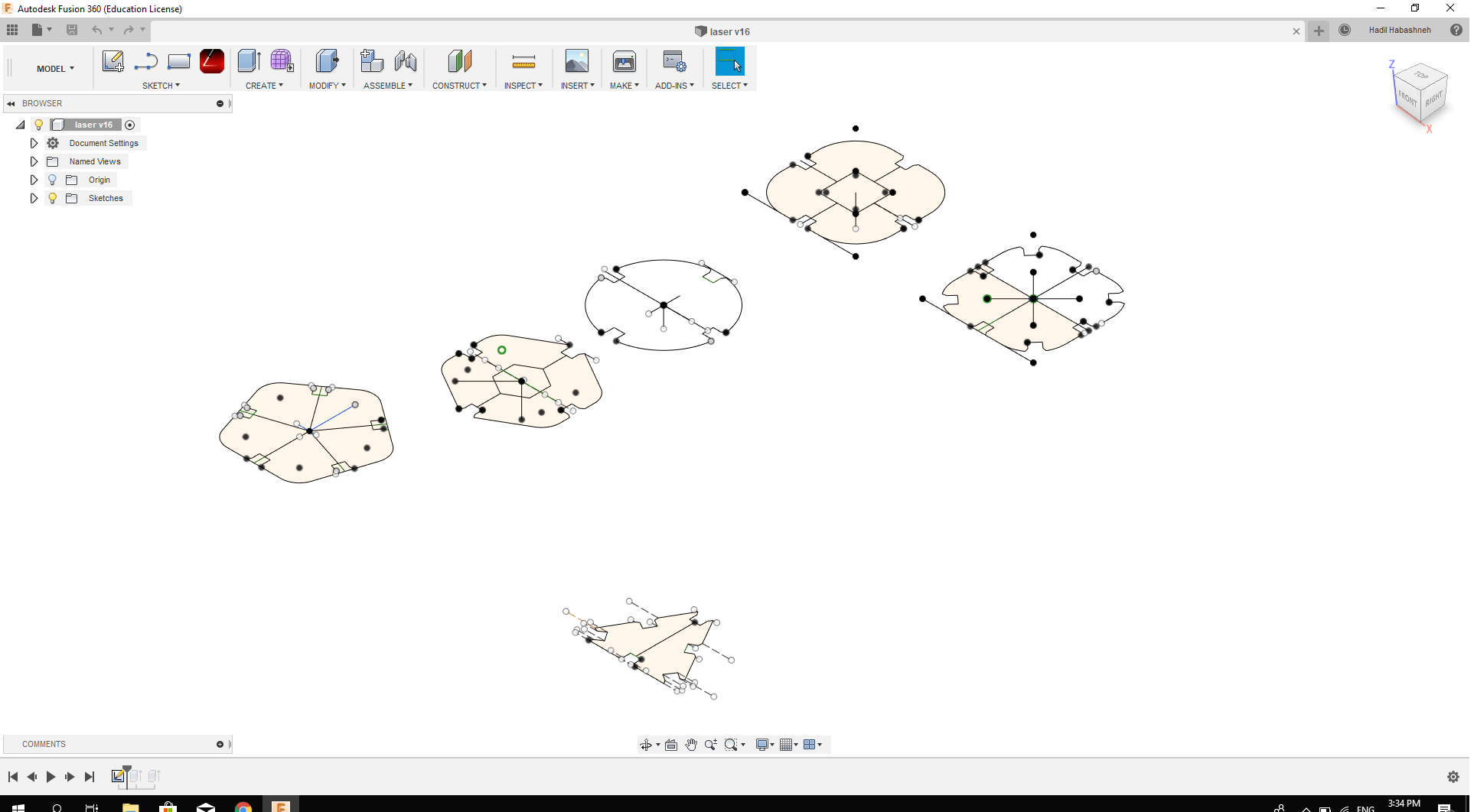
First head to model menu on Fusion360, Modify, and change parameters. A window appears where you can add the parameters’ names and values, or you can add an expression like (Y=3/X). Then, start sketching as usual, but whenever you want to add a dimension, add the parameters name. When you finish, you might still need to add more relationship between the different segments, and you’ll know you’re done when your sketch turns black instead of blue lines.
I transformed my design to parametric design by saving it as DXF file and opening it on Fusion 360, and by using the same steps I described. This didn’t work though, and so I drew the parts again on Fusion using parametric system.

Here is the
final file.