“When Moore’s Law (everything digital gets faster, cheaper , and smaller at an exponential rate) and Technology joined together, an explosive force was unleashed that changed the very nature of innovation, relocating ir from the center (governments and big companies) to the edges (a twenty-three-year-old punk rock musician and circuit-board geek living in Osaka, Japan).” - Joi Ito
Embedded Programming
This week I followed a tutorial to program the board from the Electronics Design week.
The BoredBoard
I used my recently done hello.ftdi.44 remix board to do this week assignment on embedded programming. I renamed the board to BoredBoard, as I didn't have anytime to be bored by doing the board. I used all of the available pins of the ATtiny44 by connecting them to some components I'm going to talk about.
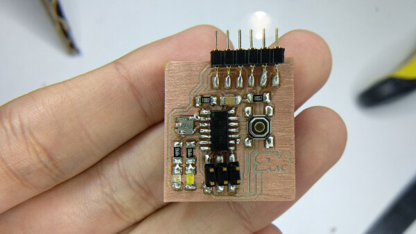
The inputs and ouputs on the board to play with are:
- 2 leds (1 blue and 1 white)
- 1 switch button
- 1 general GND/AnalogSignal/VCC input, now plugged to a potentiometer.
Datasheet
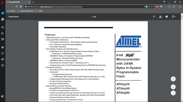
- ATTiny44 Datasheet (Complete).
- ATTiny44 Datasheet (Summary).
All of the electronic components must have a datasheet, that is a very extensive (generally) sheet of text that specifies every part of the component, from how to program it, to the general pins, and in the case of the microcontrollers, how to modify the clock inside the component.
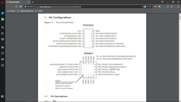
The first part is very important to read is the pinout section. Must of the components have one. There it is specified what does every pin in the component means, so you can design a circuit around the microcontroller. For example, in the VCC I connected the positive end of the power supply, and on the GND the other end.
There is a block diagram in the datasheet that specifies every part inside the component. As you can imagine there is an entire world inside this tiny component.
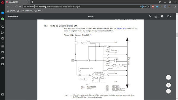
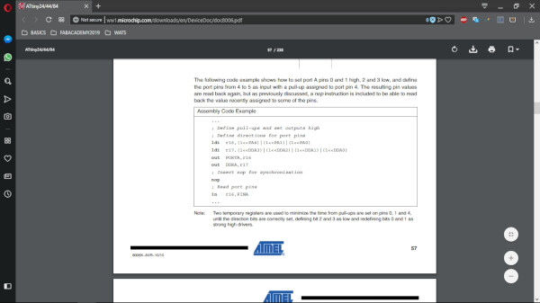
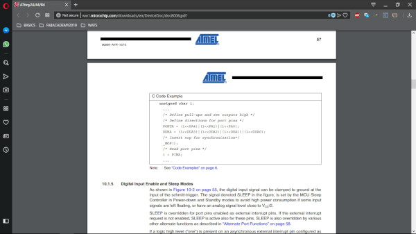
In the section of Programming in C, down in this page, I used a section of the datasheet called I/O Ports to modify the pins of the microcontroller.
Programming the BoredBoard
Set Up
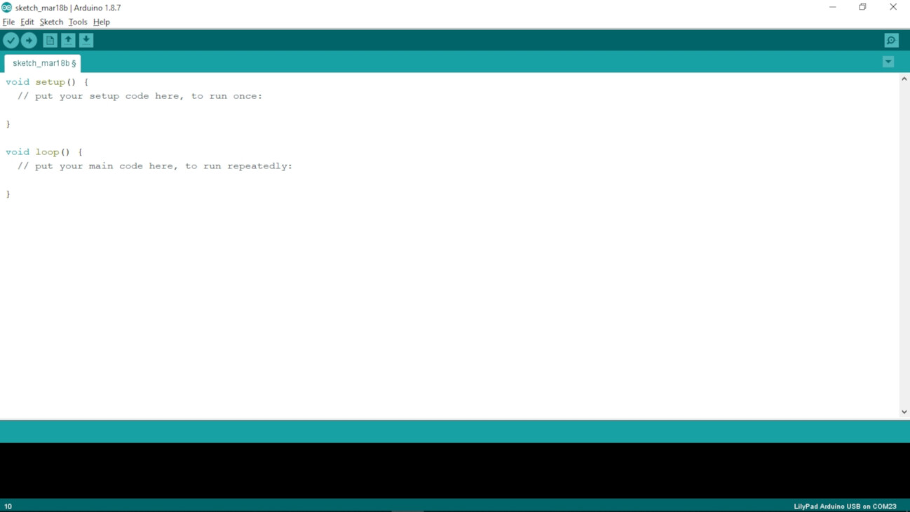
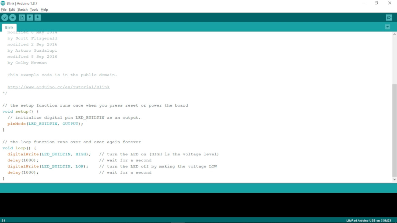
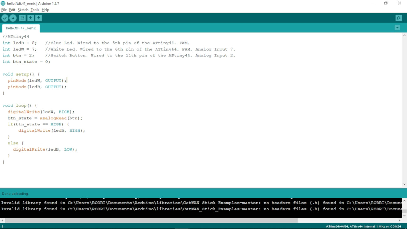
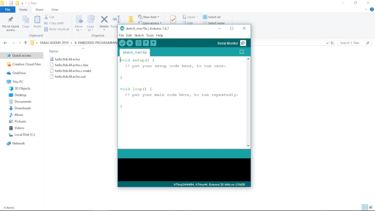
First I downloaded the Arduino IDE for Windows. This is how the software looks like.
I had previously experience using Arduino, so I'm very familiar with the interface and coding using the Arduino functions. To use my FabISP as a programmer and my BoredBoard as a programmable board, I followed this legendary tutorial from the High-Low Tech at MIT MediaLab.
I'll show you a quick tutorial on what I did, but I highly recommend the High-Low Tech tutorial, as it has more insights on the ATTiny family.
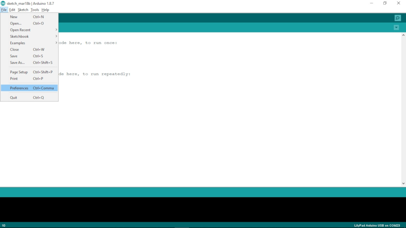
- Go to File > Preferences
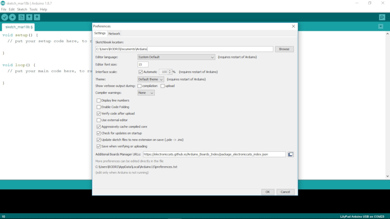
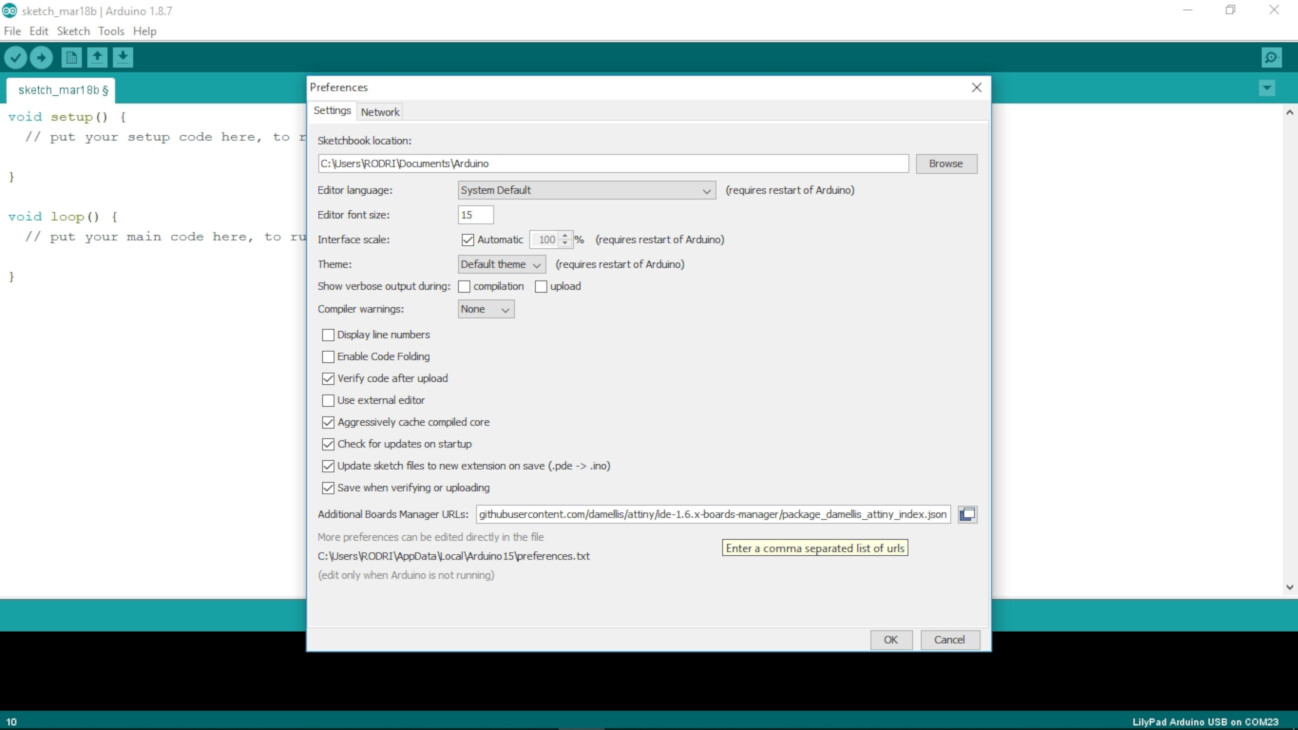
- On the Preferences windows, on the Additional Boards Manager URLs section, paste the followed link (Note: if you have already a URL like I did, just write a "," at the end of the previous one and then paste the new one):
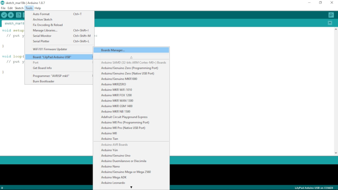
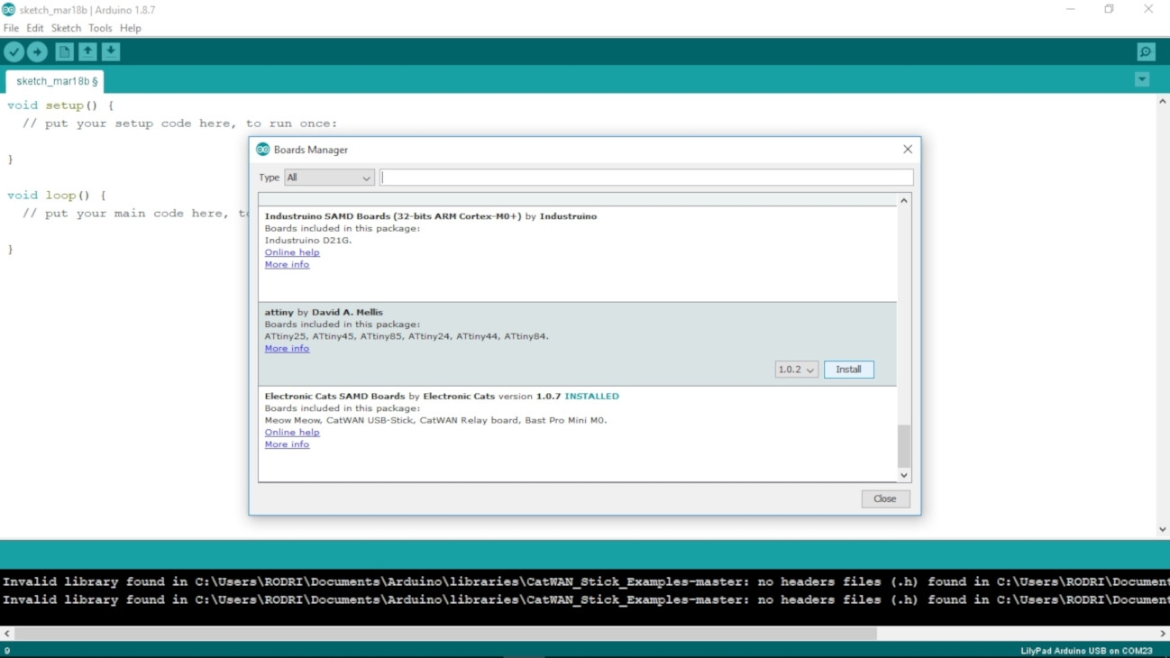
- Go to Tools > Board > Boards Manager...
- On the Boards Manager window, look for the "attiny" by David A. Mellis package, and click Install. Then close the window.
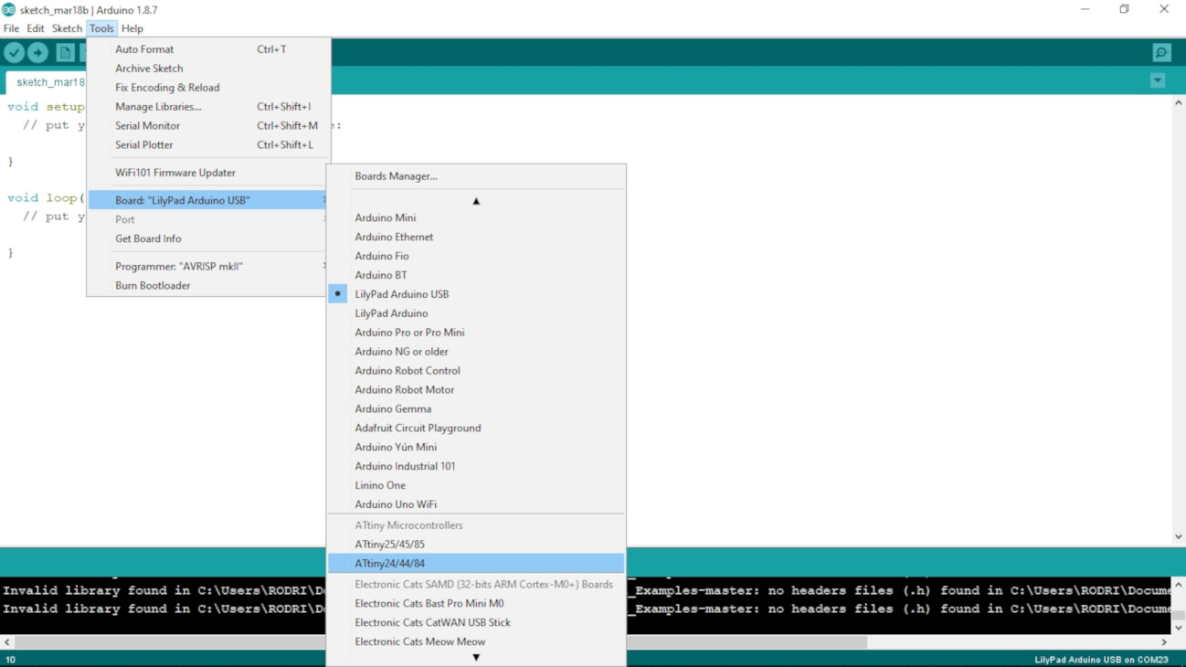
- Go again to Tools > Board, and select the ATtiny24/44/84 under the ATtiny Microcontrollers section.
https://raw.githubusercontent.com/damellis/attiny/ide-1.6.x-boards manager/package_damellis_attiny_index.json
Connect the BoredBoard to the FabISP
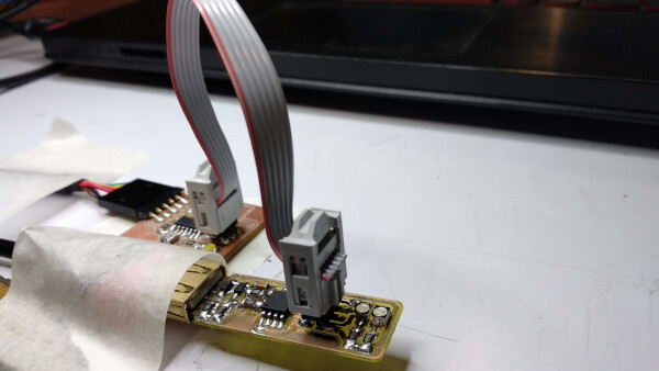
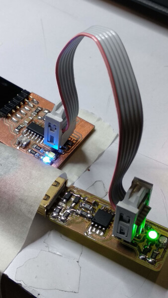
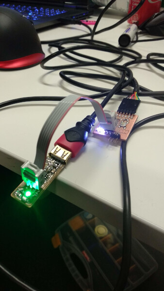
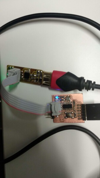
Now it's all set up, I connected the BoredBoard to the FabISP through the ISP headers. Be sure to connect correctly the GND pins. I show two angles of the connections
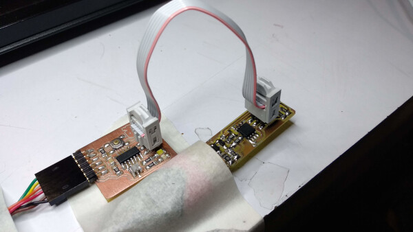
Then I plugged the BoredBoard to the computer through the FTDI pins, using a FTDI-USB cable. Plugged the FabISP to the computer, for this I used a USB-USB extension to easy the connections. When it's all connected, the led on the FabISP should turn on. Mine is a green led. I should remark the importance of this step because I was following the tutorial with the FTDI-USB cable unplugged, and obviously nothing worked for me, until I noticed it and the plugged it.
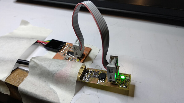
If your led don't turn on, maybe the connection between your board and the FabISP through the ISP pins is wrong, try rotating the cable.
Uploading a code to the BoredBoard
- Go to File > Examples > 01.Basics > Blink. This will open a code for making the leds on the BoredBoard blink.
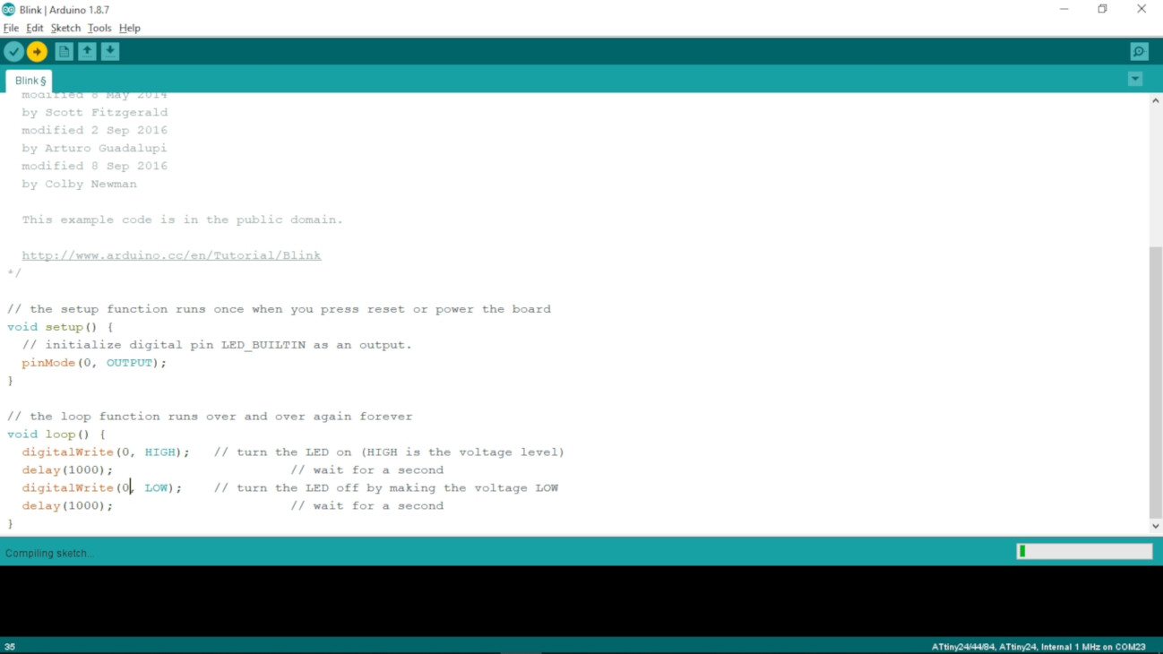
- In the tutorial, it says to change the LED_BUILTIN to 0, in the setup() and in the loop() of the code.
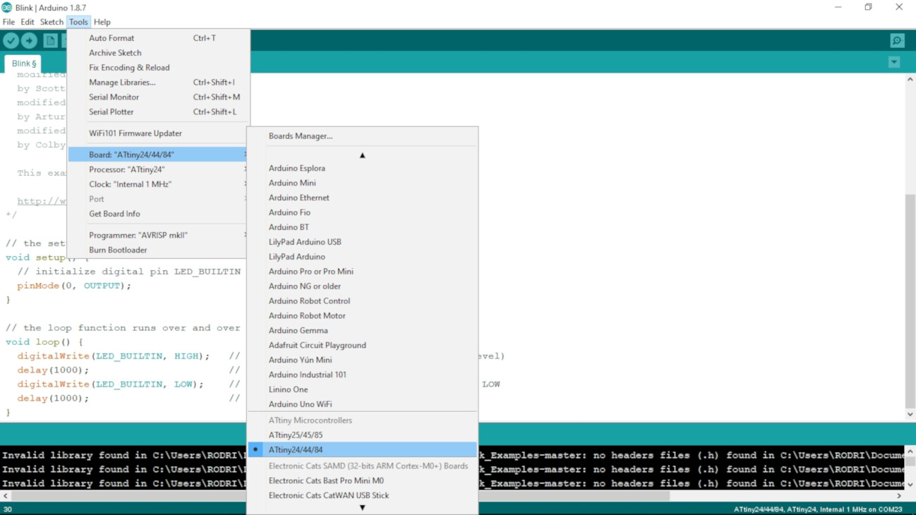
- Go to Tools, you should have selected:
- Board: "ATtiny24/44/84"
- Processor: "ATtiny44"
- Clock: "Internal 1MHz"
- Go to Tools > Programmer, select the USBtinyISP
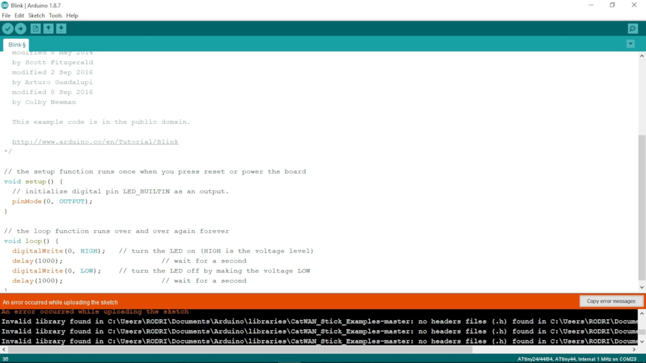
- Upload the code by Sketch > Upload, by the combination Ctrl+U, or by hitting the arrow button on the top left.
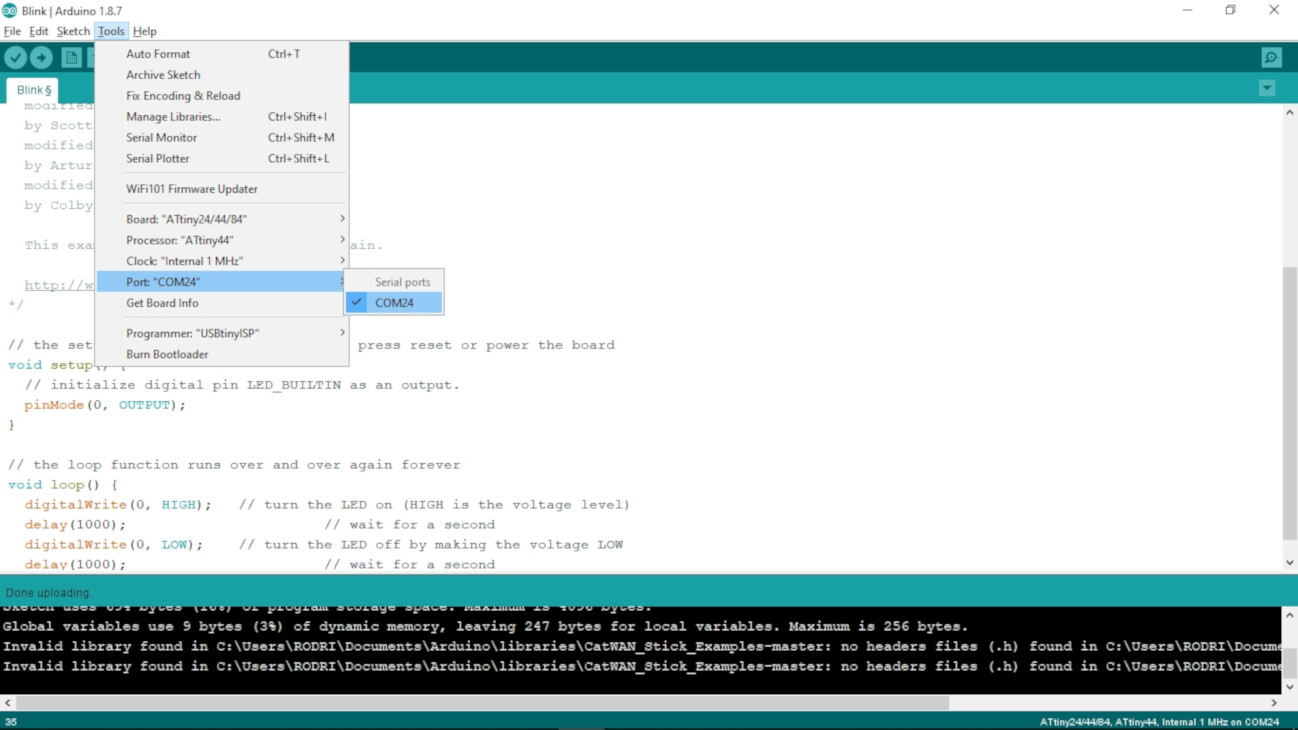
I got an error. The reason was that I didn't select a port. So go to Tools > Port and select the one it appears.
Now there's a message of Done Uploading, but my BoredBoard is not doing the blinking. The reason for this is that you have to check in which pins of the ATtiny are your inputs and outputs connected. I used this image as reference. As my leds are connected to the 5th and 6th pin of the ATtiny44, the corresponding Arduino pins are 8 and 7 respectively. So I tried by changing the 0 of the code to 8.
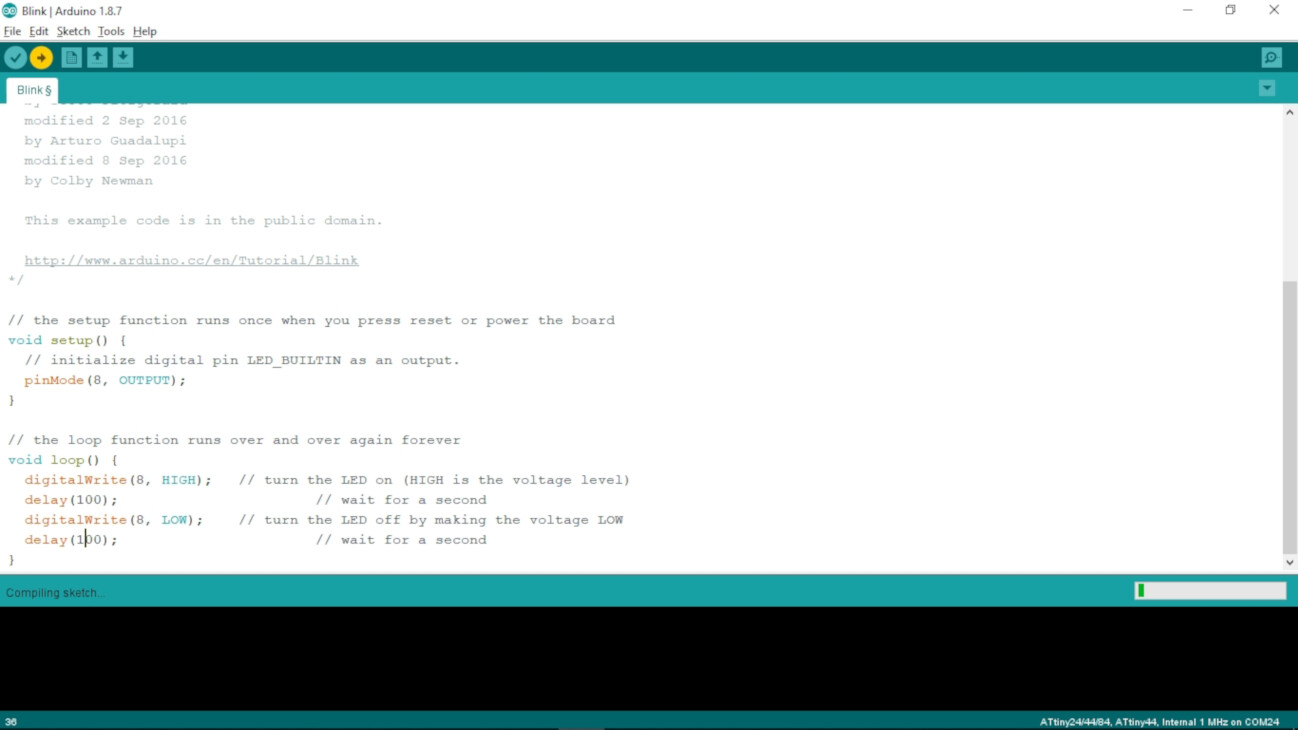
And now the blue led blinks!
Now I can upload some basic code into my BoredBoard, but I'm using the 1MHz internal clock for that. In my board I have an external 20MHz clock, so to use some cool serial functions and use the clock I need to do a few more steps.
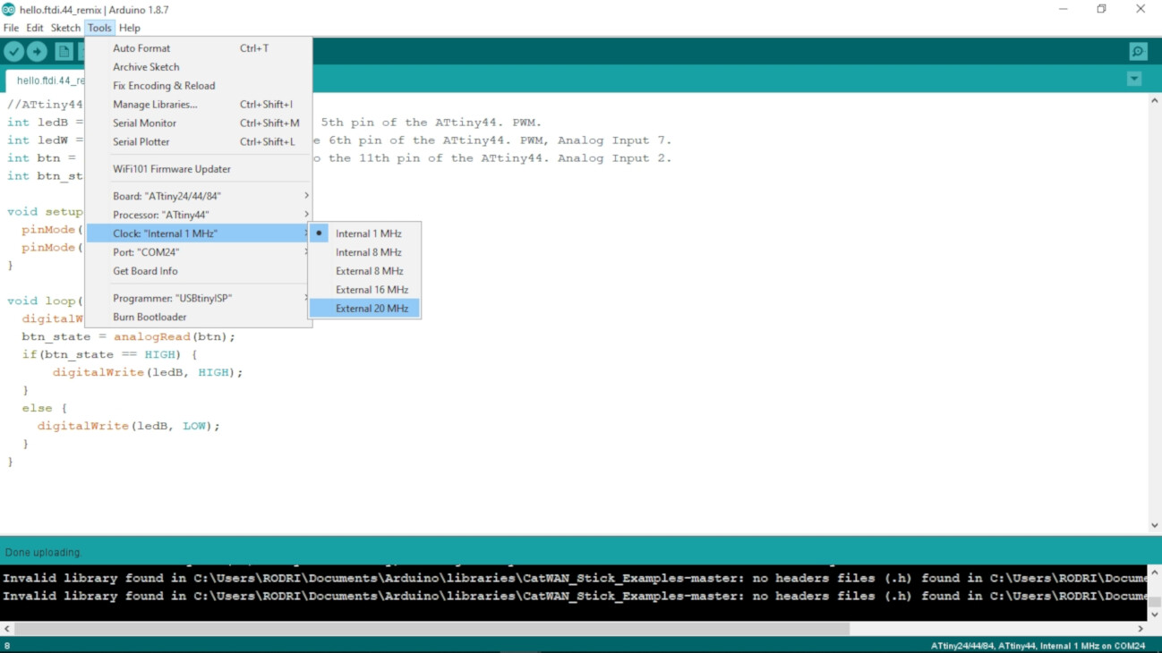
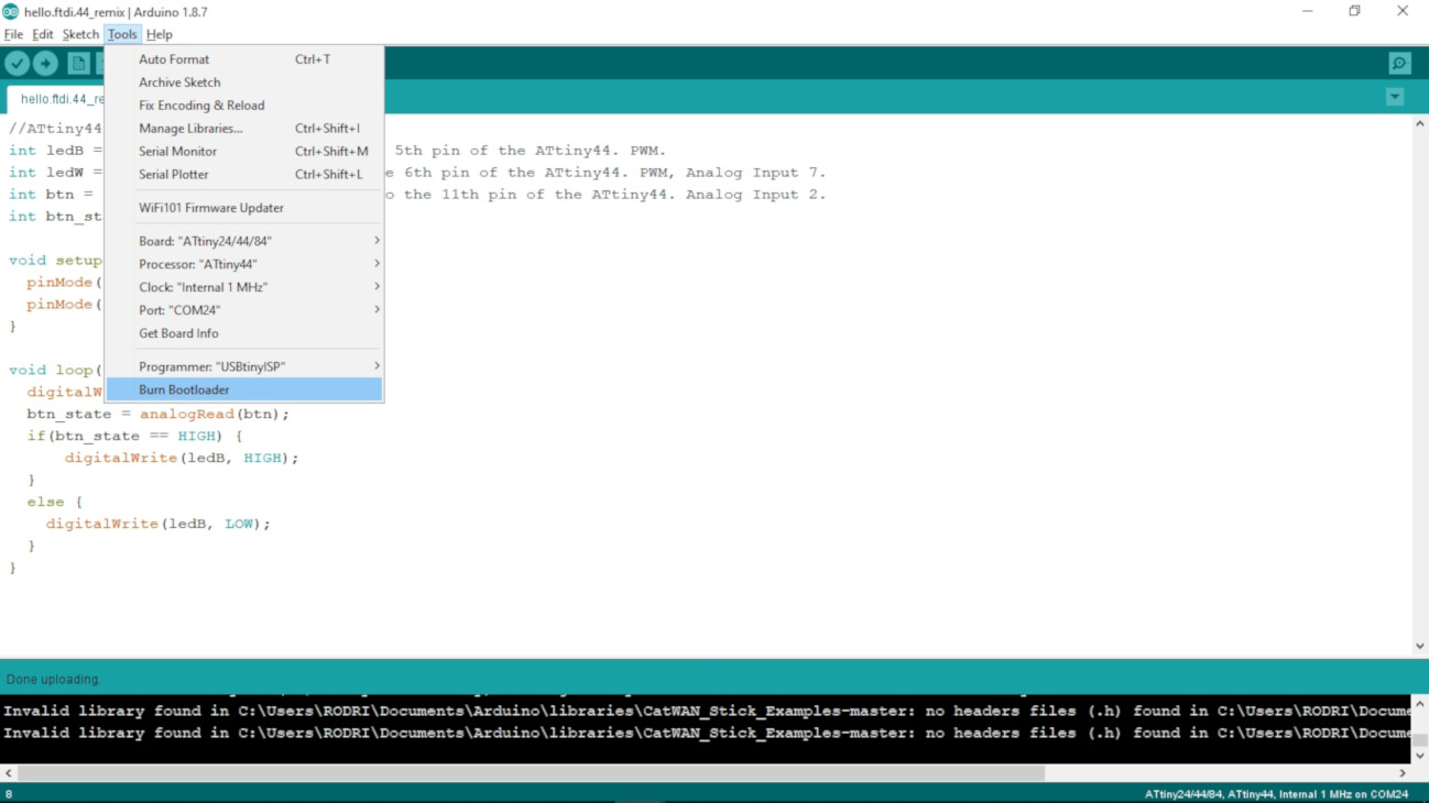
Using the 20MHz external clock and burning the bootloader
First I wrote some code to use the two leds and the switch button on my BoredBoard.
- Go to Tools > Clock and select the External 20MHz.
- Go to Tools and select Burn Bootloader.
Testing the Serial monitor
To test the serial, I found this tutorial and copied this code and simplify it. Then I uploaded the code to the BoredBoard
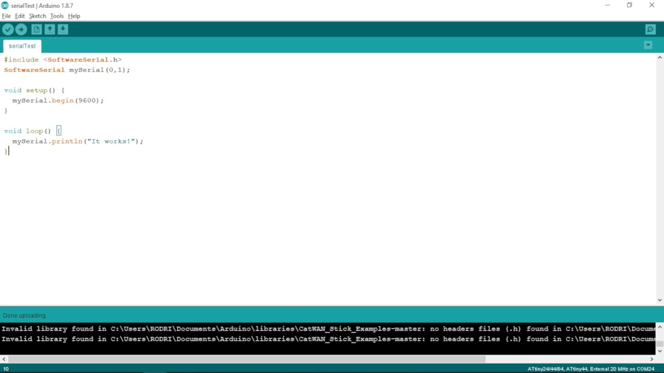
By running this code, and if everything works great, it should show on the serial monitor the text "It works!"
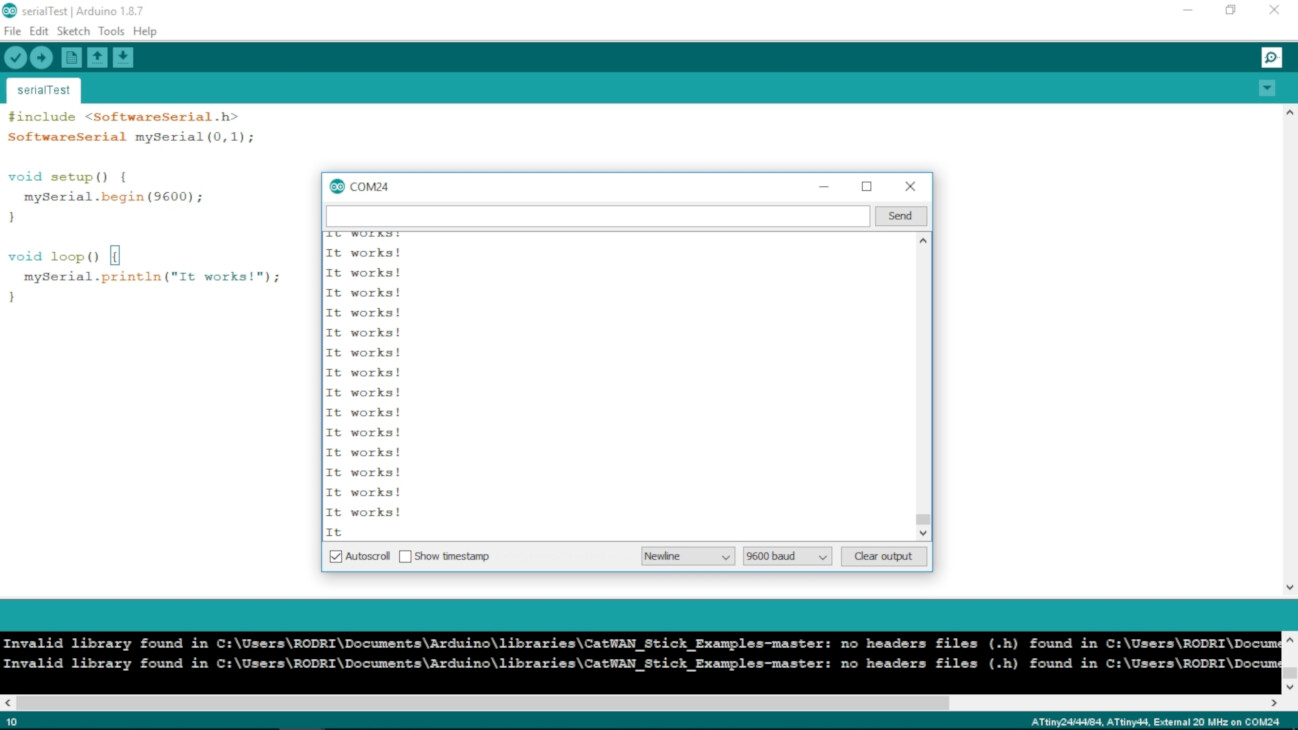
It works!
Uploading the C code through the terminal
The next challenge was to upload some C code to the board using the terminal. To do this I followed this FabAcademy tutorial but is incomplete as it don't have the commands. Then I found the original tutorial that has all the commands.
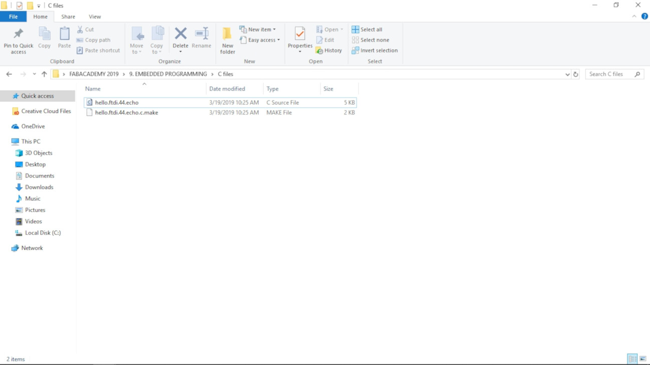
- I downloaded this two files by right-clicking and selecting Save As:
- hello.ftdi.44.echo.c
- hello.ftdi.44.echo.c.make
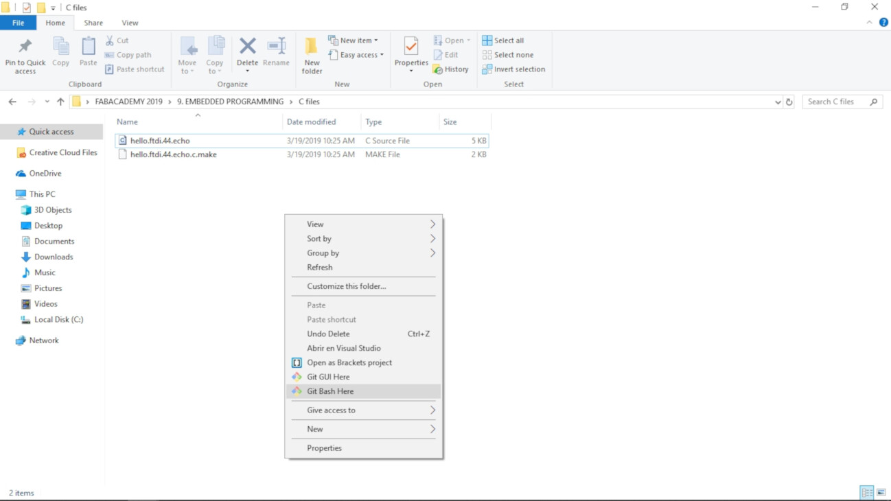
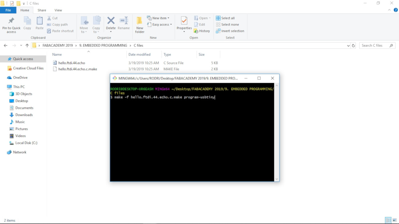
- I opened a Git Bash terminal on the folder. If you open a terminal elsewhere, you have to navigate to the folder where you have both files using the cd command.
- Run this command:
- make -f hello.ftdi.44.echo.c.make program-usbtiny
- make -f hello.ftdi.44.echo.c.make program-usbtiny-fuses
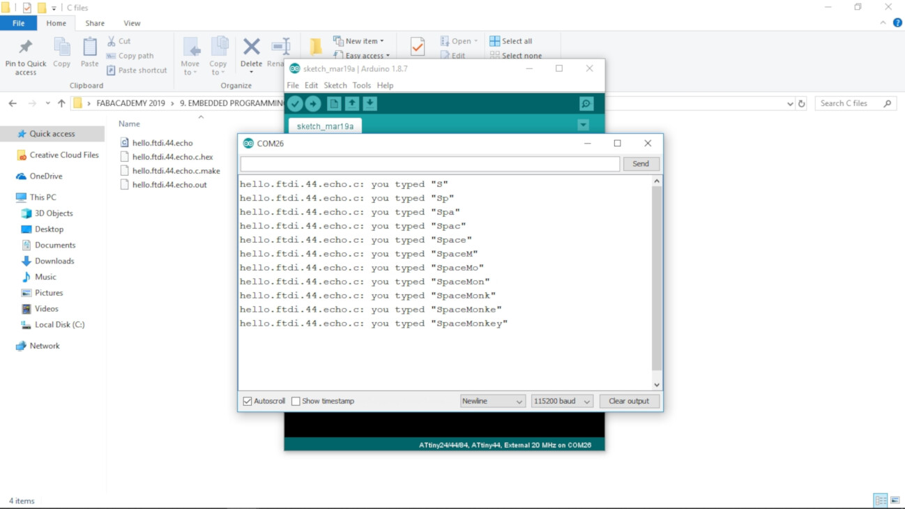
- The led of my BoredBoard turned off, that means that it has now another program. To check if the echo code uploaded correctly I opened the Arduino Serial monitor and typed: SpaceMonkey letter by letter.
I recommend to put the two files into a folder. I named the folder "C files" in the FabAcademy folder I have on my computer.
This generate a .hex and a .out files on the folder. If an error appears, try setting the fuses first by running this command
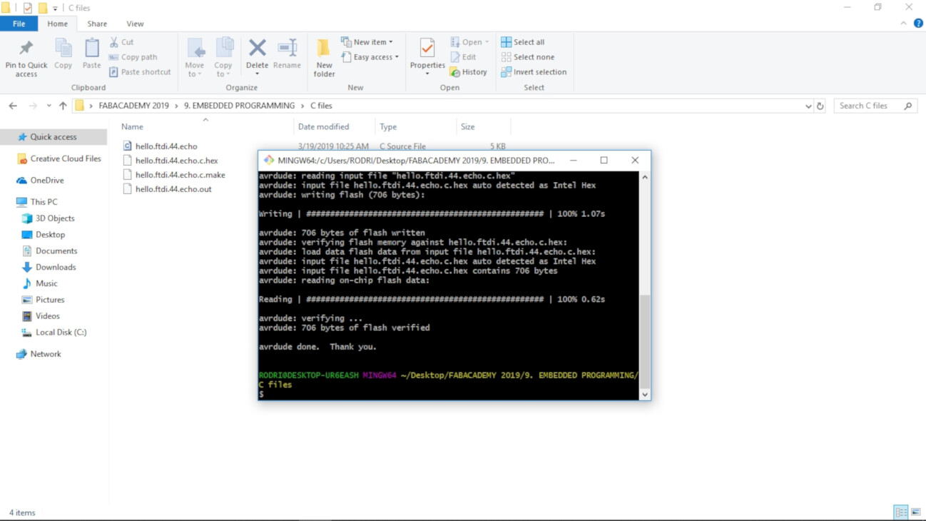
The code uploaded correctly!
Programming in C
To do the programming in C of some codes, I followed my instructors, Marta Verde FabAcademy assignment. My comparing her code to Neil's, I noticed little changes I could make on the code. First I copied Neil's files of hello.ftdi.44.echo and hello.ftdi.44.echo.make, and paste them into another folder. Then I renamed the files as boredboard and boredboard.make respectively.
I then opened the .make file in Brackets and modified the header:
- I wrote "PROJECT=boredboard" insted of "PROJECT=hello.ftdi.44.echo"
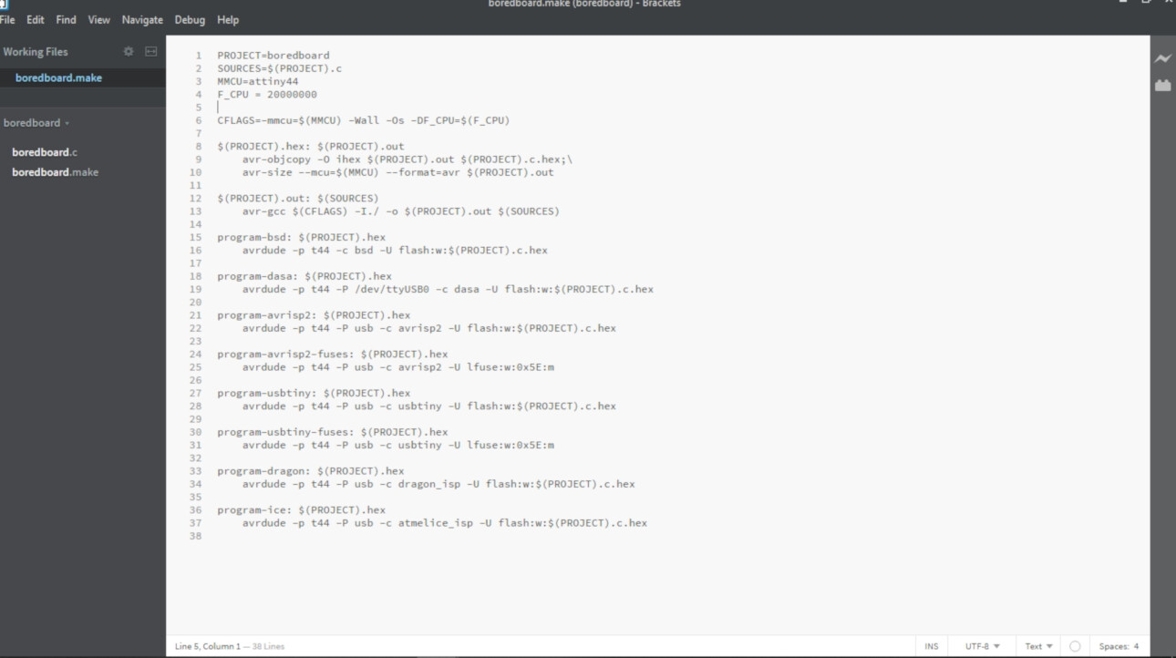
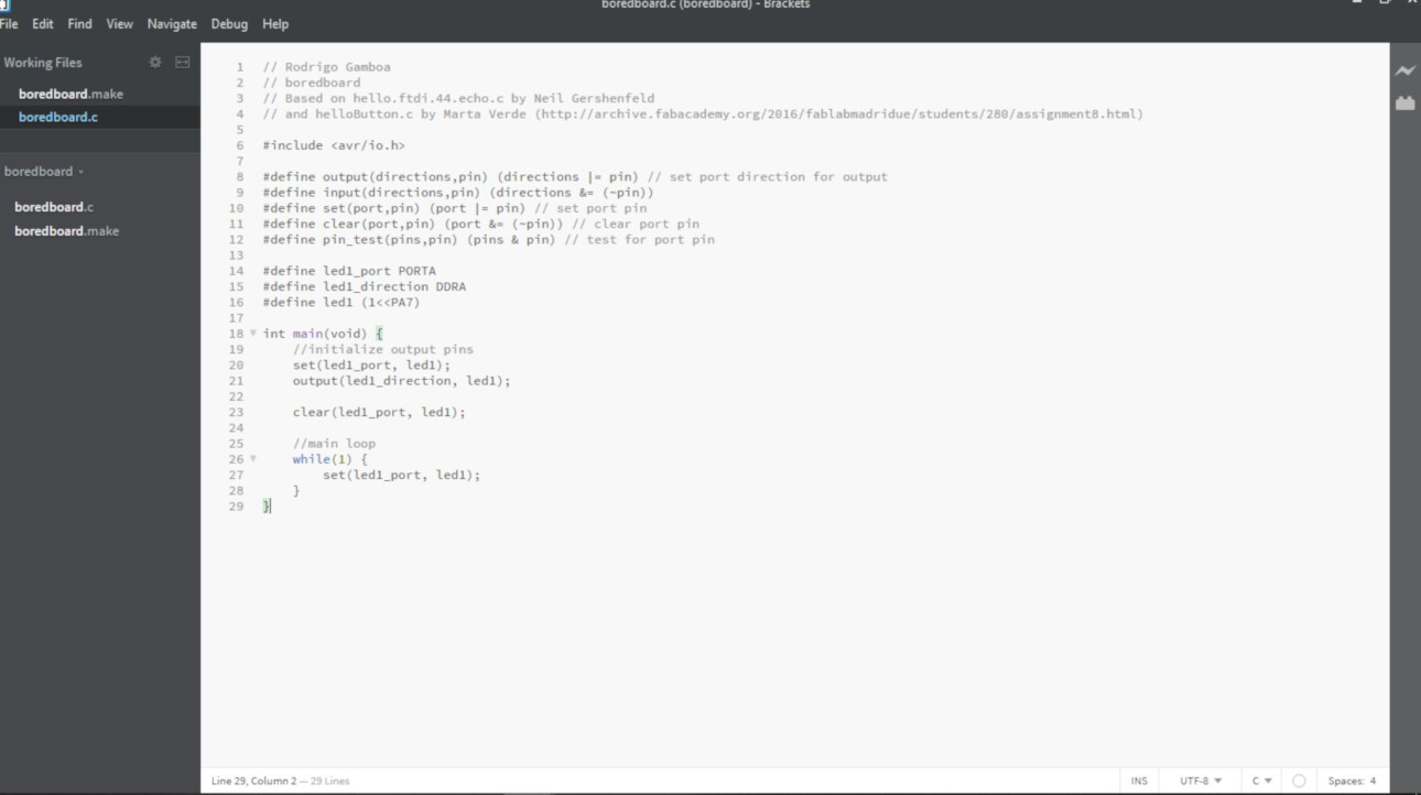
I opened the boredboard file in Brackets and change it to this:
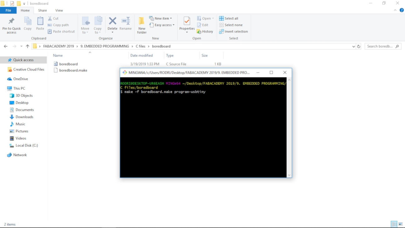
And I ran the next function on terminal:
- make -f boredboard.make program-usbtiny
Then the white led turned on in the BoredBoard!
To make the modification on the code I had to go to back to the datasheet of the ATTiny44. There is a section called I/O Ports. In this sections there says how you can change the purpose of each of the pins on the microcontroller. You can change it as an output or an input (that's what the I and the O means on the I/O). To do this there are different Ports. There is an example code on the datasheet that I followed to change the code and turn on the led.
To turn the other led I have to make changes on the code. The led that turned on is connected to the PA7 pin, and the other one to the PB2 pin. So I, as the datasheet indicates, I have to modified the PORTA to PORTB and the PA7 to PB2:
- Wrote "PORTB" instead of "PORTA" in the line 14.
- Wrote "PB2" instead of "PA7" in the line 16.
I ran the program an the blue led turned on! But I don't know why it seems significantly less bright than the white one.
Files
Arduino Codes
C code files
Group Assignment
To see this weeks group assignment click here.