"Our technologies have outpaced our ability, as a society, to understand them. Now we need to catch up." - Joi Ito
Electronics Production
This week we started working with electronics. First I read the documentation on the FabISP to know exactly what it is and how does it work. I to fabricate it I followed this tutorial.
Important stuff!
Milling tools diameter:
- 1/64" = 0.015625 in = 0.397 mm
- 1/32" = 0.03125 in = 0.794 mm
- 1/16" = 0.0625 in = 1.588 mm
Copper thickness is the resulting thickness when 1 oz of copper is pressed flat and spread evenly over a one square foot area. I used this reference
Copper thickness:
- 1 oz = 0.00137 in = 1.37 mils = 0.0347 mm
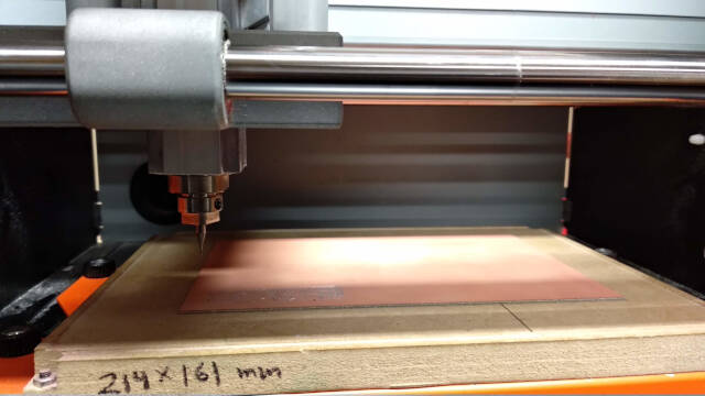
PCB fabrication
Preparing the board
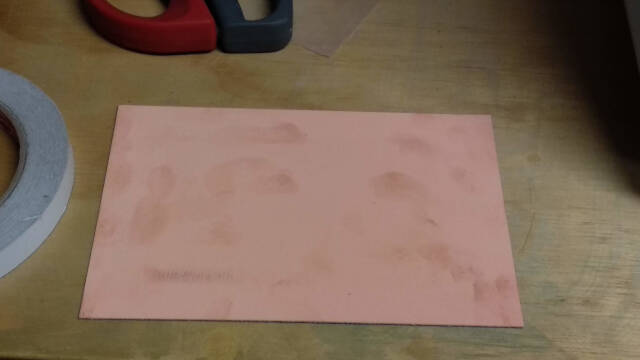
I watched this video. As I didn't understand how to generate the .rml, I'll use FabModules this time. If that works and I have time I'm going to try with mods.
Open VPanel, make sure that both boxes are in the User Coordinate System option.
I'm using this default parameters:
- 1. speed(mm/s): 4
- 2. cut depth(mm): 0.1
- 3. tool diameter(mm): 0.4
- 4. number of offsets(-1 to fill): 4
- 5. offset overlap(%): 50
- 6. path error(pixels): 1.1
- 7. image threshold(0-1): 0.5
- 8. sort path: check
- 9. sort merge diameter multiple: 1.5
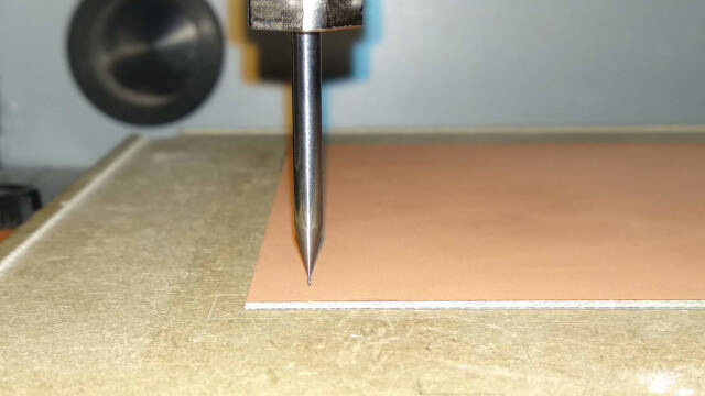
I snapped a mill tool... My copper clad board thick is 8m. I did'nt measure it before using it! Big mistake. I'm gonna try to use an extra reach mill tool, as is the only one left that is not broken :|. This time I'm gonna change the parameters of FabModules.
This time I'm using this parameters:
- 1. speed(mm/s): 1
- 2. cut depth(mm): 0.04 (As the copper thickness is 0.0347mm)
- 3. tool diameter(mm): 0.4 (It should be 0.397mm but I think this should work)
- 4. number of offsets(-1 to fill): 4
- 5. offset overlap(%): 50
- 6. path error(pixels): 1.1
- 7. image threshold(0-1): 0.5
- 8. sort path: check
- 9. sort merge diameter multiple: 1.5
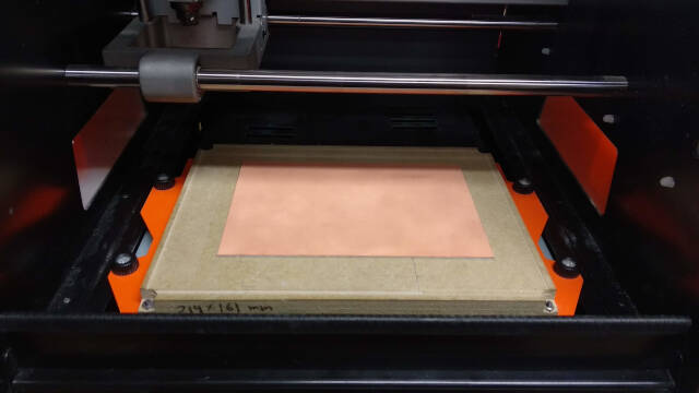
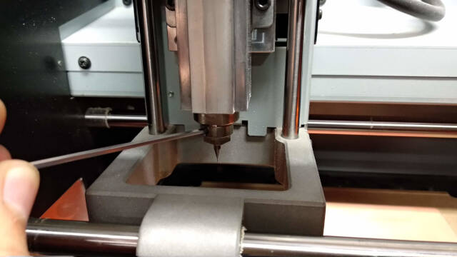
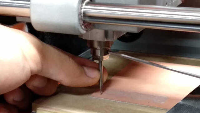
This time I calibrated the height of the mill tool by using the center of the plate as reference, as there is a possibility that the board is a little deformed and the center is higher.
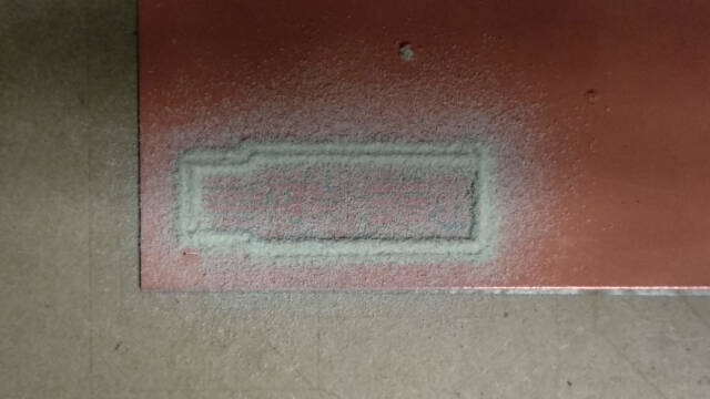
After sending the file to cut, I had to wait until the tool cutted where it was already cutted before. After a few minutes, finally the tool was cutting in a new place. I waited a few seconds, and click the Pause button to see how the cutting was. It seemed that the tool was not cutting deep enough.
It seemed that the cut depth I used (0.04 mm) is not right, because the tool was moving a lot and making some curved cuttings (put photo of the curved lines) so by advice of Jesús, the machine manager in the Fab Lab Yucatán, I'm going to change the cut depth to 0.08mm. So I have to generate again the .rml. So I canceled the ob on the VPanel by clicking the big Cancel button.
After generating the .rml again, I send it to the machine.
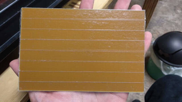
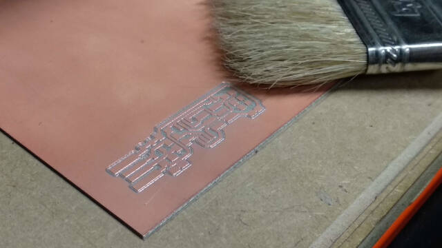
This time it worked!
Now I'm going to change the tool for the 1/32". The procedure now is to "meter" the tool very deep. Then move the "machine head" to the origin by clicking To Origin X/Y, Z on the VPanel (put photo of vpanel with some arrows). Now loose the tool and "bajala" until it touches the plate (don't drop it! the tip of the tool could break).
Go to Fabmodules:
- 1. speed(mm/s): 2
- 2. cut depth(mm): 0.6 (As the copper thickness is 0.0347mm)
- 3. tool diameter(mm): 0.4 (It should be 0.397mm but I think this should work)
- 4. number of offsets(-1 to fill): 4
- 5. offset overlap(%): 50
- 6. path error(pixels): 1.1
- 7. image threshold(0-1): 0.5
- 8. sort path: check
- 9. sort merge diameter multiple: 1.5
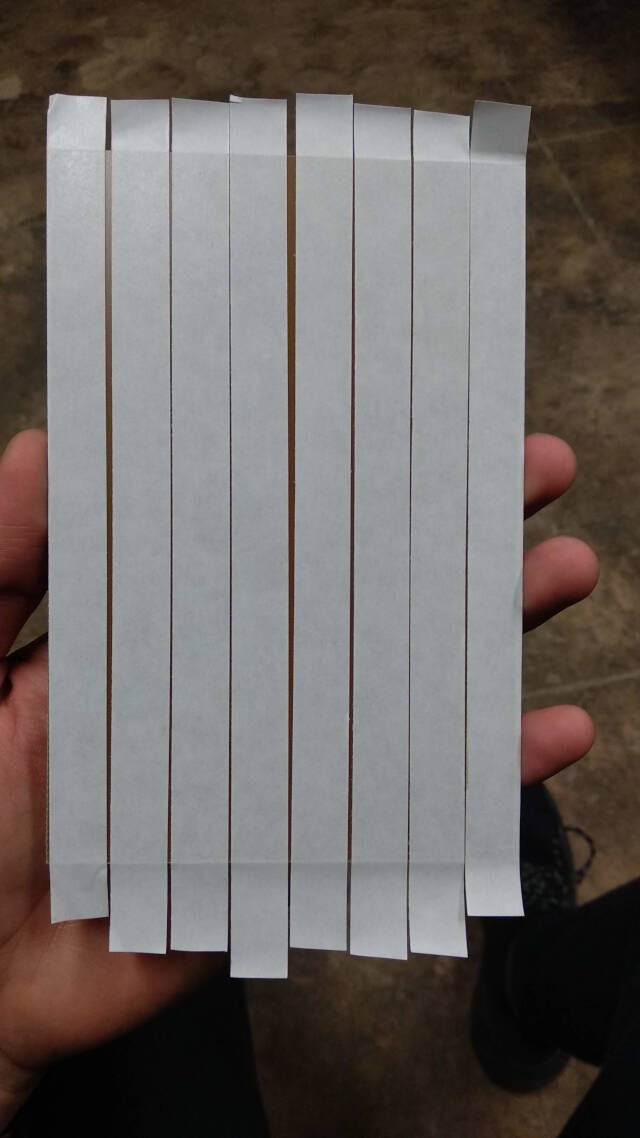
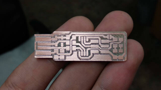
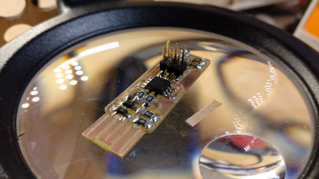
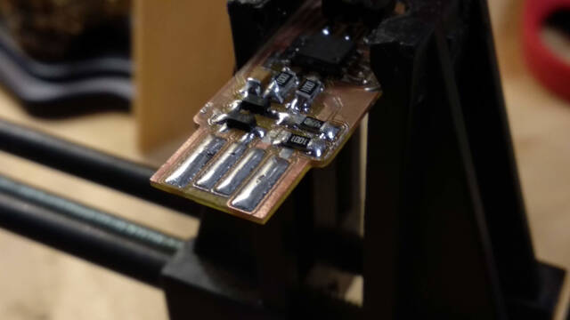
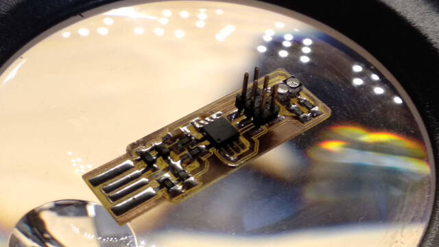
The final cut is extremely thin, so I'll have to make something to make it work as an usb interface. I used a 220 sandpaper. I have to be careful because this board is FR-4 that means it has fiber glass and a lot of sharp debris.It is not recommended! You should use FR-1, but that was the only thing available for me at the moment. Be careful sanding it, use gloves!
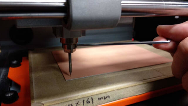
Note: The cutting starts at 7mm on the x axis, and 6.5 on the y-axis.
There's a few traces that weren't cutted, but as I removed the board before noticing it, it was too late to remill it. I used the multimeter to probe continuity and if there was a short circuit between traces. Fortunely, everything was okay, but next time I mill a board, I'm gonna make sure everything is well cutted before removing the board.
Materials && Components
Material I used:
- Solder iron
- Sponge
- PCB holder
- Solder
- Solder paste
- Kapton tape
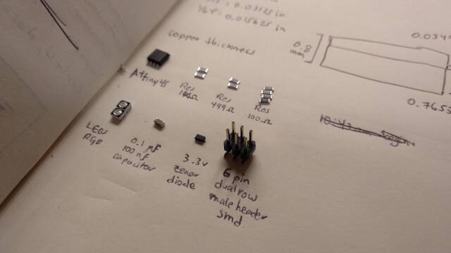
I ordered the components to identify them. There's a few components I'm missing, like red and green leds, and 49 ohm resistors. I do have some RGB leds, so I'm going to use two of them and just connect one pin to select a single color. And fort the 49 ohm resistors, I have some 100 ohm resistors, so if I solder them in parallel (Ohm's Law), I should have 50 ohm. This is going to be an experiment and I hope it works!
Components for the board:
- 1 x Attiny 45
- 2 x 1 kΩ resistor
- 2 x 499 Ω resistor
- 4 x 100 Ω resistor
- 2 x RGB LED
- 1 x
- 2 x zenerdiodes
Soldering
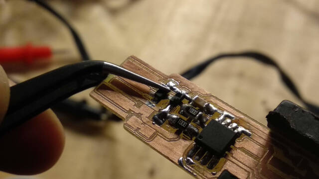
Solder usb traces
- 1. To tin (estañar) the traces, you copper needs to be very clean, so first you have to use some thin sandpaper over the traces.
- 2. I used kapton tape to contain the solder only where I want It, at the end of the USB pads.
- 3. Put paste over the pads.
- 4. Rub your soldering iron gently over the pads. Add a little bit of solder to create the bumps.
Programming the FabISP
Before sticking the FabISP into a USB port of a computer, is extremely important to debug the board. I checked for some short circuits with the multimeter. It seemed that everything was fine.
For programmin on Windows 10 I used this tutorial.
This are the steps I followed:
- I had already installed Git and Bash (add links).
- Downloaded the AVR Toolchain for Windows [here](https://www.microchip.com/mplab/avr-support/avr-and-arm-toolchains-c-compilers), version 3.6.2.
- After downloading it, extract the folder in "C:\Program Files".
- Download [GNU Make](http://fab.cba.mit.edu/classes/863.16/doc/projects/ftsmin/make-3.81.exe), run the installer and extract the files in "C:\Program Files (x86)". Additionally, you can create a desktop shortcut.
- Download [AVRdude](http://fab.cba.mit.edu/classes/863.16/doc/projects/ftsmin/avrdude-win-64bit.zip) and extract it in "C:\Program Files".
- Open the Windows Control Panel > System and Security > System > Advanced System Settings. Click the Environmental Variables button under the Advanced tab.
- Select Path and click the Edit button.
- Select New and add the following three paths:
- C:\Program Files\avr8-gnu-toolchain-win32_x86\bin
- C:\Program Files (x86)\GnuWin32\bin
- C:\Program Files\avrdude\bin
- ADD NOTE ON SELECTING SAME FOLDERS THAT YOU HAVE.
- Click OK on all the open windows.
- I THINK THIS STEP IS WRONG! --- Downloaded [Zadig](https://zadig.akeo.ie), version [2.4](https://github.com/pbatard/libwdi/releases/download/b721/zadig-2.4.exe), and launched it.
- I THINK THIS STEP IS WRONG! --- I plugged the FabISP into a USB extension and my computer didn't recognized it. I should have selected the USBtinySPI in Zadig, but it didn't apperead. So, I clicked on Options > List All Devices. Clicked on Install Driver. The installation failed. I made sure my USB port was working correctly by plugging a USB memory stick. Everything was alright, so I have to fix the unrecognized issue.
- To program my board I'm using an official AVR ISP programmer, so I downloaded and installed [Atmel Studio 7.0](https://www.microchip.com/mplab/avr-support/atmel-studio-7), [web installer version](http://studio.download.atmel.com/7.0.1931/as-installer-7.0.1931-web.exe).
- Connect the official AVR ISP programmer (I'm using [version 2.0](https://www.seeedstudio.com/Atmel-AVRISP-STK500-USB-ISP-Programmer-p-207.html)).
- Open Git Bash and try some commands:
- make -v
- avr-gcc --version
- THIS COMMAND SHOWS "avr-gcc.exe (WinAVR 20100110) 4.3.3", when the tutorial showed(avr-gcc.exe (AVR_8_bit_GNU_Toolchain_3.5.4_1709) 4.9.2).
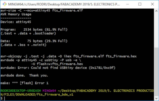
- avrdude -c usbtiny -p t45
- In this step it showed an error: Could not find USBtiny device. So I opened the programmer and see that It doesn't use an ATtiny microcontroller, so I think that's why the command that specific says "usbtiny" is not working. In the tutorial, in the Program the ATtiny45 section, it says that depending on our programmer is the new it has. I'm using what is known as the "small translucent blue programmer", which name in the command should be "avrisp2".
- avrdude -c avrisp2
- I typed this command to see if anything useful shows, and it showed the valid parts, meaning depending of the microcontroller used in the programmer, is the code. Before I used the code "t45", that means ATtiny45, but it didn't work. That's because the programmer I'm using is using an ATMEGA8535, which code is "m8535". I confirmed this by opening the programmer.
- avrdude -c avrisp2 -p m8535
- It showed me this message "avrdude.exe: ser_open(): can't open device "\\.\com1": The system cannot find the file specified.". As I'm using an offical AVRISP2.0 I'm going to ignore this message and follow with the tutorial.
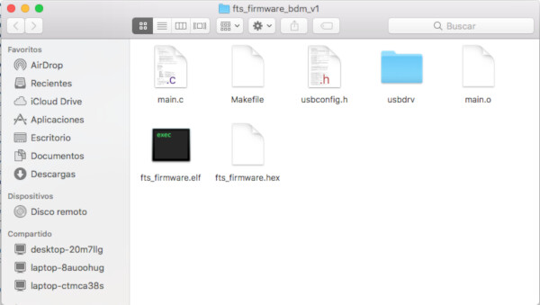
- Downloaded the [firmware source code](http://fab.cba.mit.edu/classes/863.16/doc/projects/ftsmin/fts_firmware_bdm_v1.zip) and extracted it in a local folder.
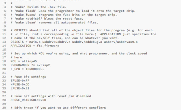
- Opened the file named "Makefile" in a text editor intended for programmers, as the tutorial suggests. I used [Brackets](http://brackets.io). Changed the line "PROGRAMMER ?= usbtiny" to "PROGRAMMER ?= avrisp2" as I'm using an official AVRISP2.0. In the tutorial you can check other options of programmers.
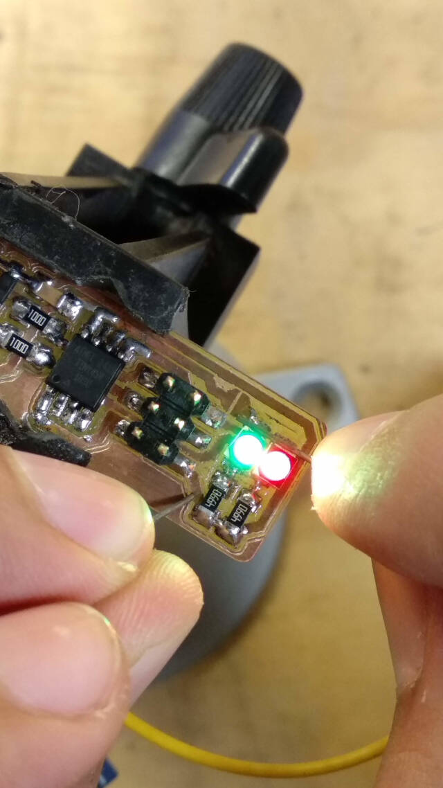
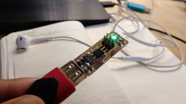
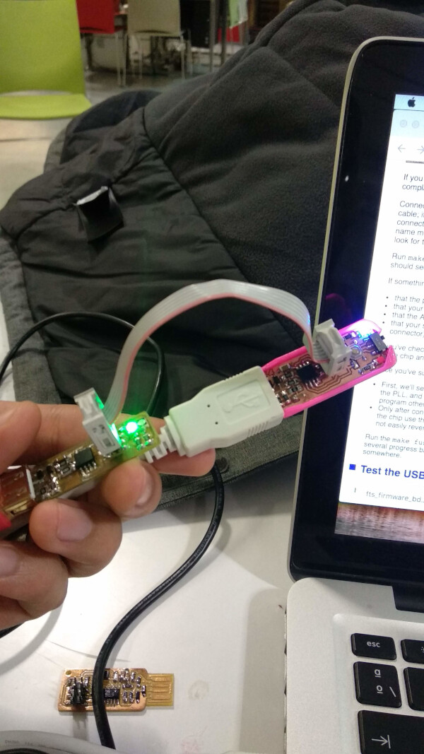
- Plugged the FabISP that I made into an USB 2.0 port, using a USB extension. The green led indicator turned on.
- Connected the AVRISP2.0 programmer header on my FabISP. The tutorial gives some advice on the orientation and how to connect it. I aligned the pin that has the arrow (MISO signal) and looked for the design of the FabISP to match it to the MISO pin. As the programmer header I have is a 10-pin connector, I'm using [this image](https://www.avrfreaks.net/sites/default/files/AVRISPMKII.png) for reference.
- Connected the AVRISP2.0 programmer into the USB computer.
- Right-clicked on the folder where the Makefile is located and clicked "Git Bash Here". Write the next command:
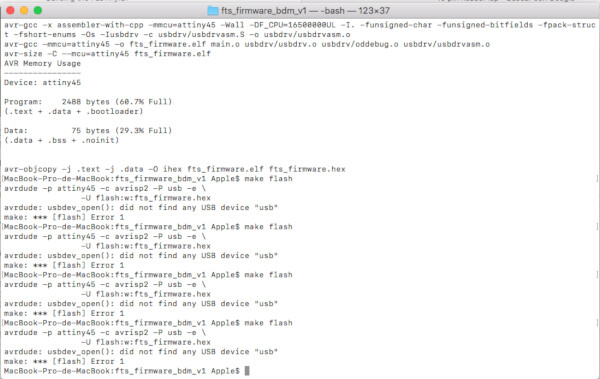
- make flash
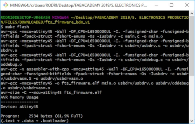
Downloaded the FabISP firmware as mentioned here, the Adafruit ones, and followed that instructions. Installed the drivers (show photo that says installing tinyisp). Didn't worked.
Just notices that when I did >>2. avr-gcc --version >>>THIS COMMAND SHOWS "avr-gcc.exe (WinAVR 20100110) 4.3.3", when the tutorial showed(avr-gcc.exe (AVR_8_bit_GNU_Toolchain_3.5.4_1709) 4.9.2).
So I changed the "avr8-gnu-toolchain-win32_x86" from Program Files to Program Files (x86), and updated the path. (Show picture) The Command avr -gcc --version still showed the same.
Another try: I connected the AVRISP2.0 programmerinto my computer, opened Zadig, go to Options>List all devices, select the one that appears to be the programmer, in my case USB-Serial Controlles, and replaced the driver from WinUSB (v6.1.7600.16385) to libusb-win32 (v1.2.6.0). It installed the driver succesfully.
Connected the fabISP and the avrisp2.0 programmer. Run the make flash. Didn't worked. Tried connecting with wires backwards (if theres a mistake in the connectors image) and didn't worked.
Fixing problems
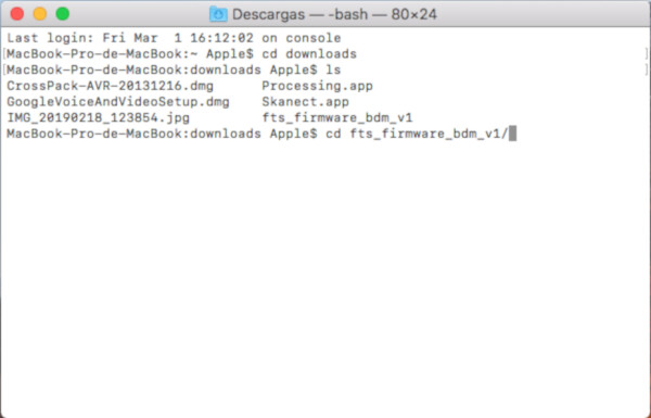
As I had available a Mac, I tried with that. First I downloaded and installed CrossPack, then I downloaded the firmware source code.
By this time I arrived to Spain and to the Fab Lab IED Madrid where I continued the FabAcademy. In the lab I had access to another FabISP.
I then opened a terminal, entered the folder of the firmware source code.
Then I used the command "make". This built the hex file.
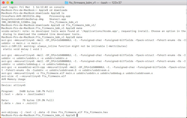
Now I had a fts_firmware.hex file in the folder.
I opened the .make file in the firmware source code, and changed:
- MCU = attiny45
- PROGRAMMER ?= usbtiny
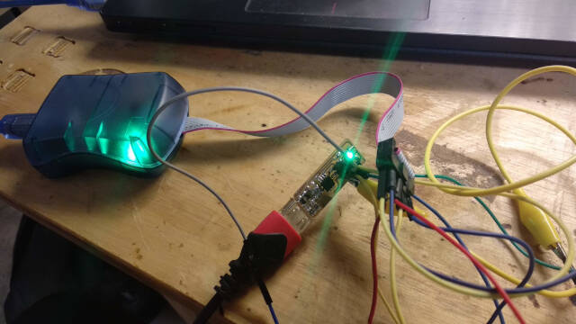
I plugged my fabISP to the fabISP avialable at the lab, I connected both of them to the Mac.
I ran the command "make flash" and this time everything went fine! I ran the command "make fuses" and again everything worked this time.
I don't know exactly why this didn't worked to me using my other laptop (Lenovo Y510P with Windows 10), but I guess it was some driver that was not updated.
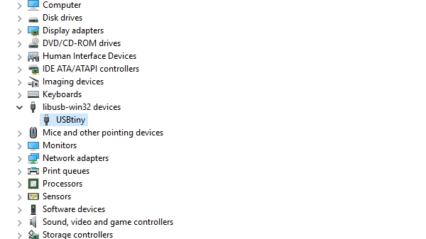
Now I (finally!) can use my fabISP, it is being recognized by my computer and can use it to program other boards!
Group Assignment
To see this weeks group assignment click here.