3. Computer Aided design
This week I’m exploring parametric 2D & 3D modelling in Rhino with Grasshopper.
Assignment in context to final project
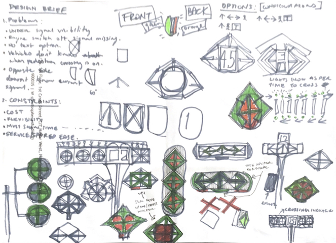
I’m targetting my final project to be related to automated traffic intersection interaction. I have selected Rhino for modelling my prototype for its ease of interoperability and its parametric capabilities.
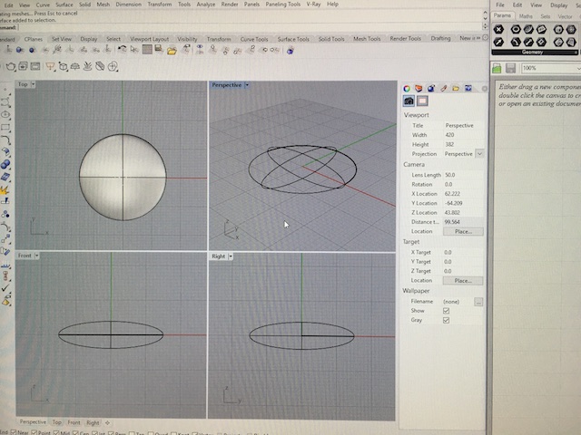
Simple 3D modelling of traffic light
In order to achieve what I wanted, I made a sphere and a box using the standard solid shapes available in Rhino.
I combined the two shapes using Boolean solid command.

Parametric modelling of light frame structure with Grasshopper
Next I wanted to try out parametric modeling with Grasshopper on Rhino to achieve the same shape with a few more details.
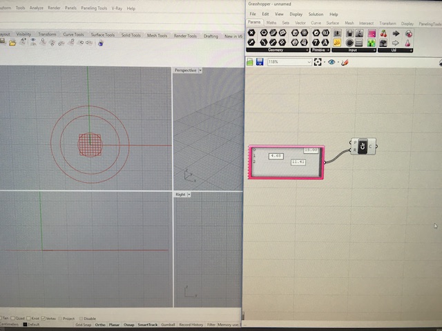
This involves adding commands and linking them with data sets in a visual scripting environment. I created a new file on Grasshopper and added a circle command and connected the radius node to a gene pool of 3 values.

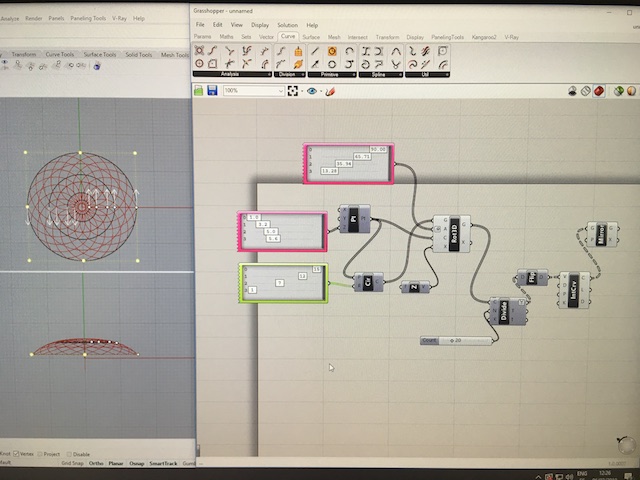
Next I added a create point command and linked the point to the same for the centre point node of the circle command. I created a new gene pool of data and connected it to the z node of the point creation command. I matched the number of values in both gene pools. The first gene pool controls the radius and the second controls the height of the hemisphere I wanted to create.

Now I wanted to go further to create regular cut outs in the surface so I added the divide command and linked the circle to the curve node.

Adding a rotate 3D command with a gene pool for the angles about Z-axis before dividing. In order to cut the curves to make enclosing lines, I added a mirror command after interpolating curve from points command and flattened curve in divide options.
The number slider for the number of divisions should be divisible by 2 and the angles divisible by 4 to ensure the lines meet, otherwise you will get results like this next image:

Moving the number slider will help you decide how many divisions you need:
Then I added an offset command after the curve and used the 2 curves to create surface. Baking the resulting surface into Rhino results in the next image. Offsetting the surface in rhino creates a solid that can be used for 3D printing.

Freecad
Openscad
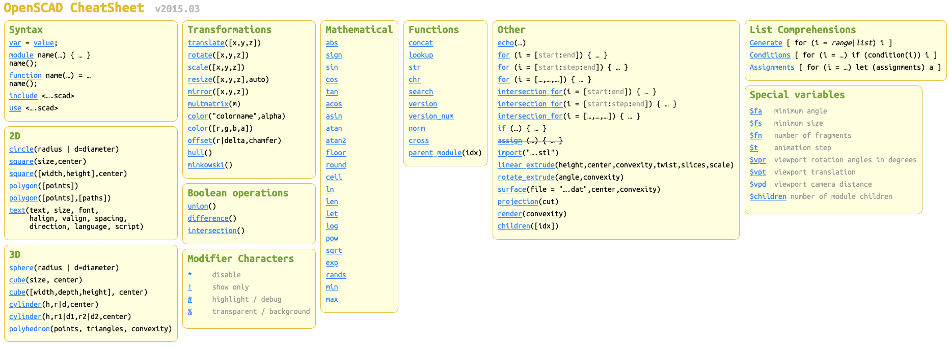
OpenSCAD is a 2D/3D and solid modeling program which is based on a Functional programming language used to create models that are previewed on the screen, and rendered into 3D mesh which allows the model to be exported in a variety of 2D/3D file formats.
A script in the OpenSCAD language is used to create 2D or 3D models. This script is a free format list of action statements.
object();
variable = value;
operator()   action();
operator() { action();    action(); }
operator()   operator() { action(); action(); }
operator() { operator()   action();
operator() { action(); action(); } }
A value in OpenSCAD is either a Number (like 42), a Boolean (like true), a String (like “text”), a Range (like [0: 1: 10]), a Vector (like [1,2,3]), or the Undefined value (undef). Values can be stored in variables, passed as function arguments, and returned as function results.
User Interface & process of design are aimed at coders and accuracy. This software is less oriented towards artists and freeform modeling. The parameters in a programmed model can be edited to suit different applications.
The special “$fn” variable sets the number of facets that are generated to create a shape. But do not tweak it only to get finer details!
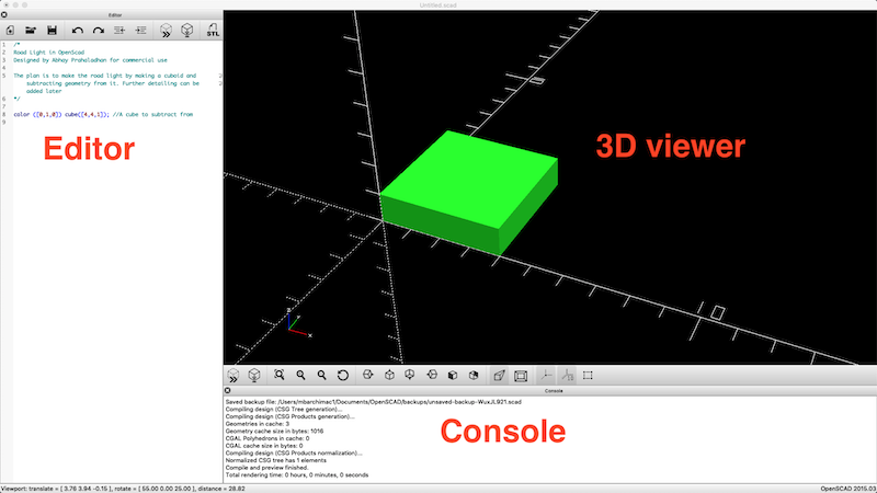
Using some tutorials, I decided to try and make the road module for my traffic light using subtractive modeling.
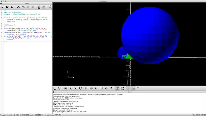
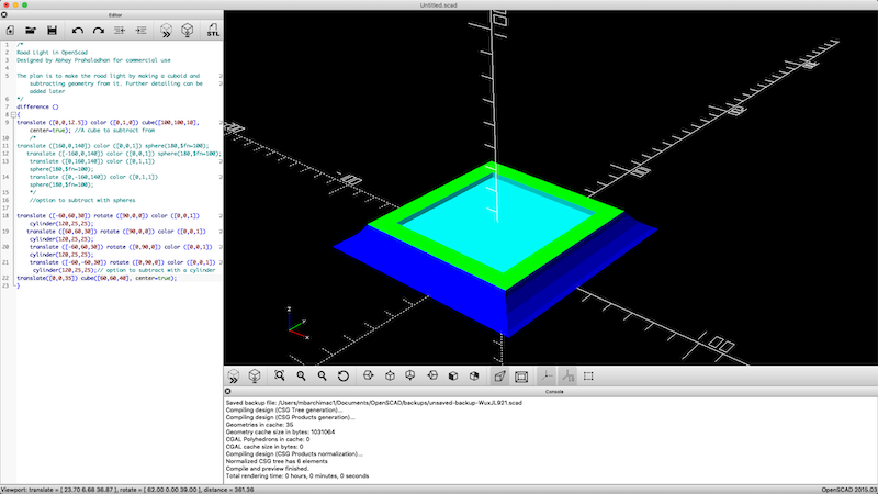
I have two options for subtracting, one with spheres and another with cylinders.
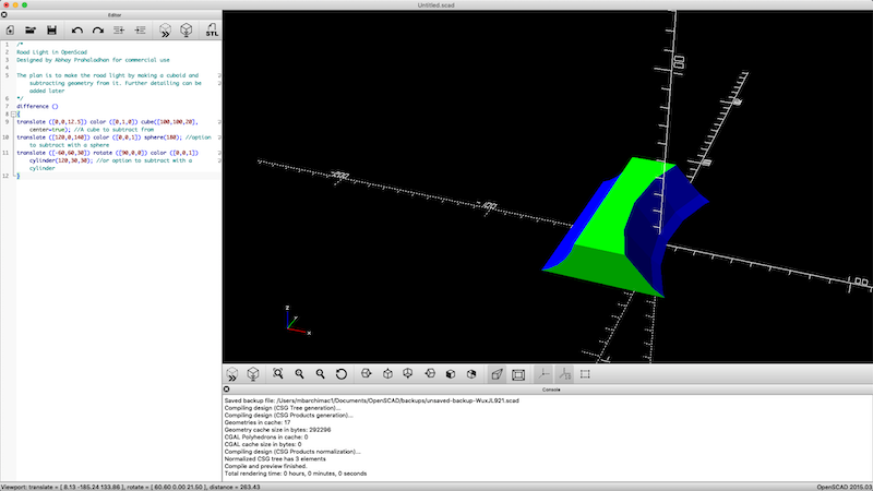
Resulting shape as shown above shows the difference between cutting with cylinder vs sphere.
The above is using cylinders cut out of a cube.
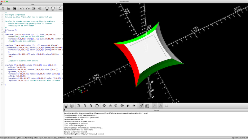
And the above is using spheres to cut out of a cube. The following is the code I wrote for the same.
/*
Road Light in OpenScad
Designed by Abhay Prahaladhan not for commercial use

The plan is to make the road crossing light by making a cuboid and subtracting geometry from it. Further detailing can be added later
*/
difference ()
{
translate ([0,0,12.5]) color ([1,1,1]) cube([100,100,10],center=true); //A cube to subtract from
translate([0,0,35]) color([1,1,1]) cube([50,50,40], center=true);//A cube that subtracts

translate ([160,0,140]) color ([1,1,1]) sphere(180,$fn=100);
translate ([-160,0,140]) color ([1,0,0]) sphere(180,$fn=100);
translate ([0,160,140]) color ([0,1,0]) sphere(180,$fn=100);
translate ([0,-160,140]) color ([0,1,0]) sphere(180,$fn=100);

//option to subtract with spheres

translate ([-60,60,30]) rotate ([90,0,0]) color ([0,0,1]) cylinder(120,25,25);
translate ([60,60,30]) rotate ([90,0,0]) color ([0,0,1]) cylinder(120,25,25);
translate ([-60,60,30]) rotate ([0,90,0]) color ([0,0,1]) cylinder(120,25,25);
translate ([-60,-60,30]) rotate ([0,90,0]) color ([0,0,1]) cylinder(120,25,25);// option to subtract with cylinders

}
Original files
Original Rhino file here
Original Grasshopper file here
STL file from Rhino here