Back to Mónica Pedro ←main page ←Final Project
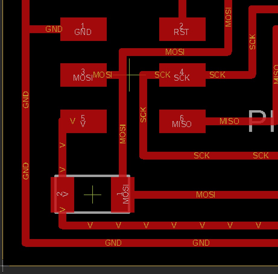
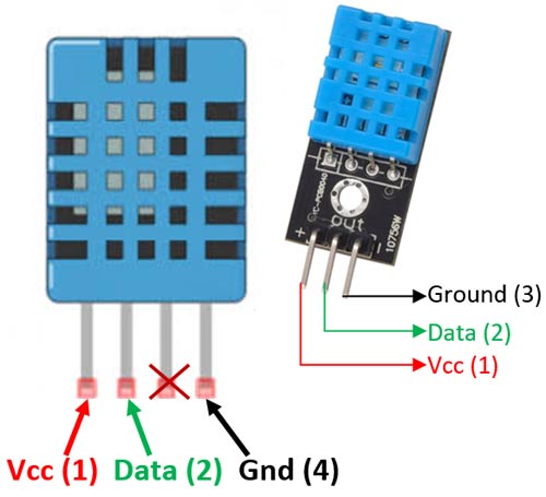
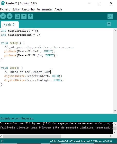
The program to upload to my Board which as a Attiny44... please see the Hardware Architecture here

First I need to study its behaviour using the Powersource to check its heating velocity and control values
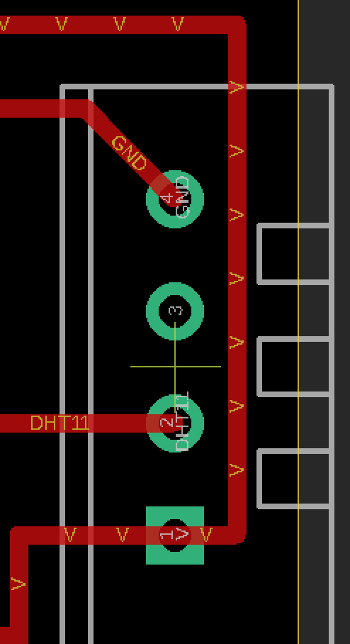
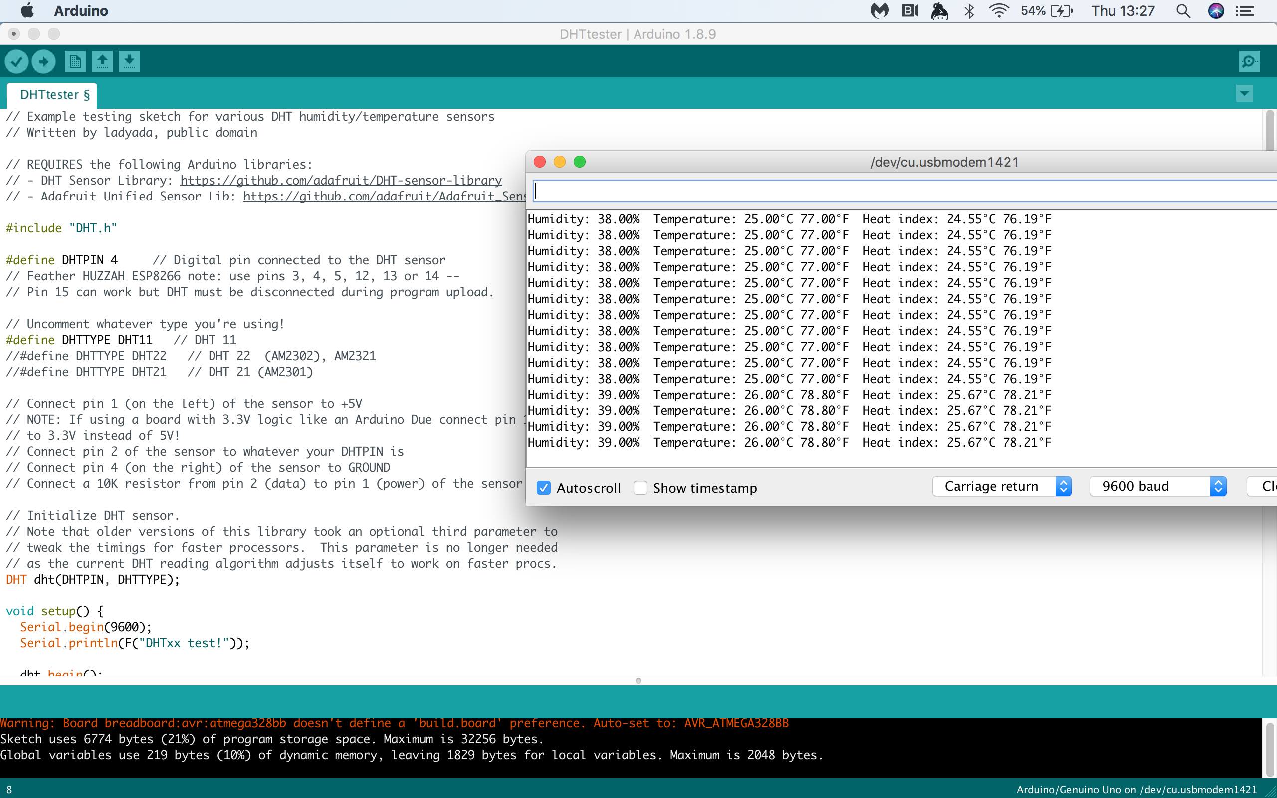 First sketch for DHT11 test
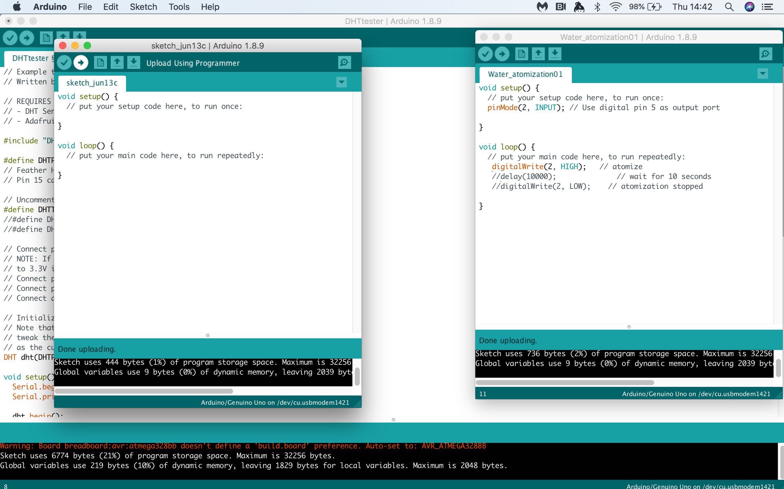
the logic was to Upload the Sketch that turns ON the pin... and when Wanted to close it, I uploaded the EMPTY SKETCH...
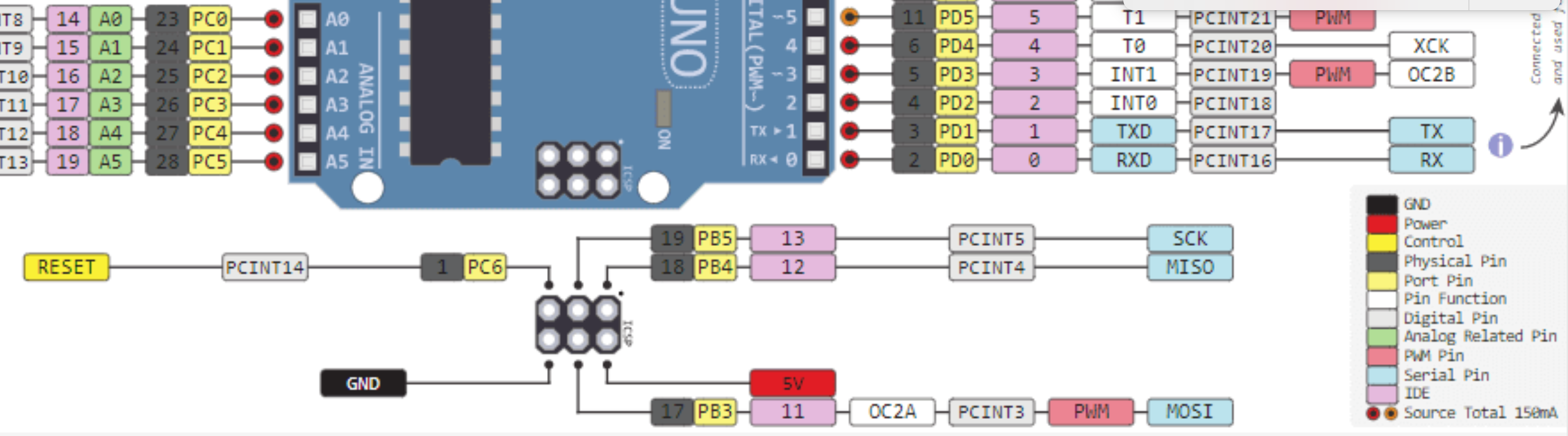
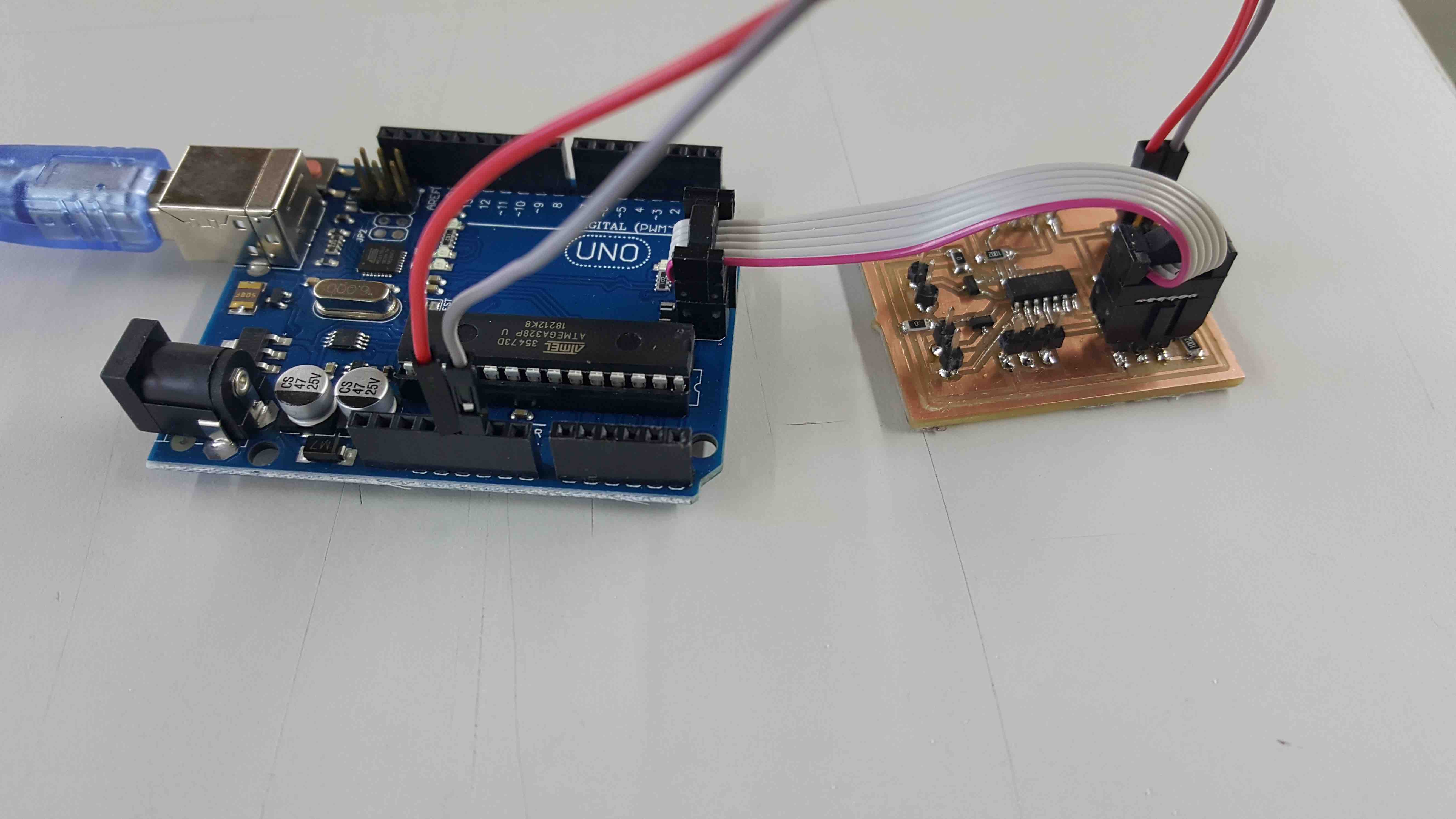
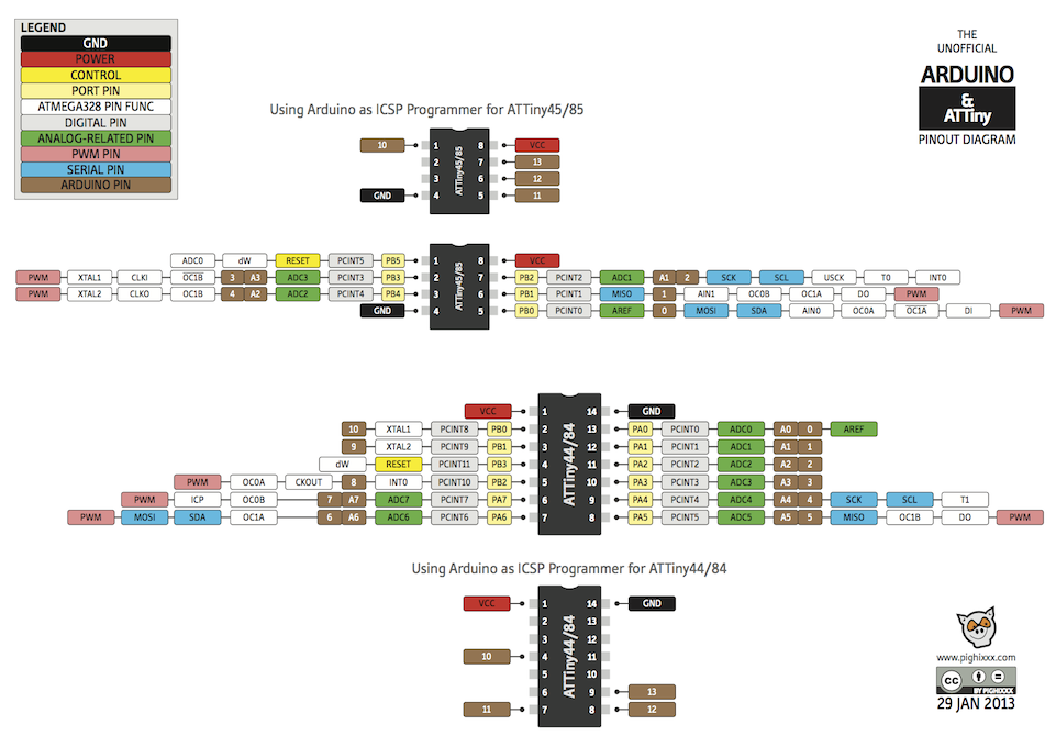
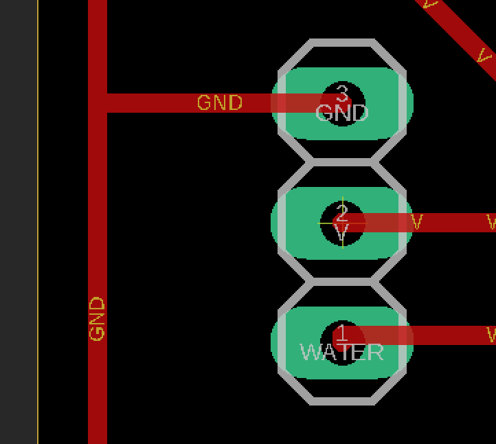
First sketch for Water AtomizationSetup Arduino As ISP using Arduino IDE:
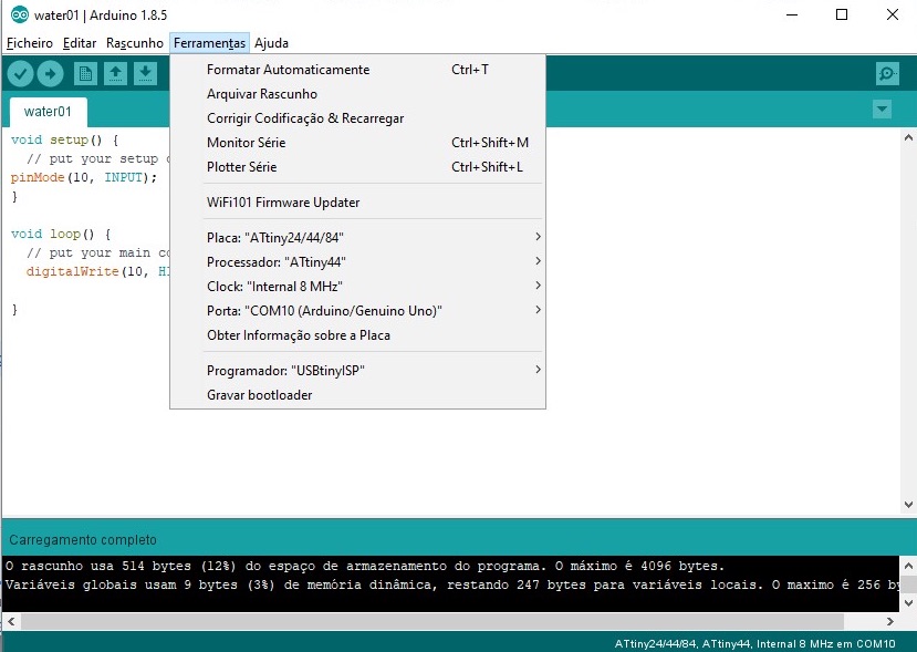
I need to install the Attiny Board and found a nice article on this... Program an ATtiny44/45/84/85 With Arduino
And its alive... :)
// DHT11 Pin = 13 (in ATtiny44) = 0 (Arduino IDE)
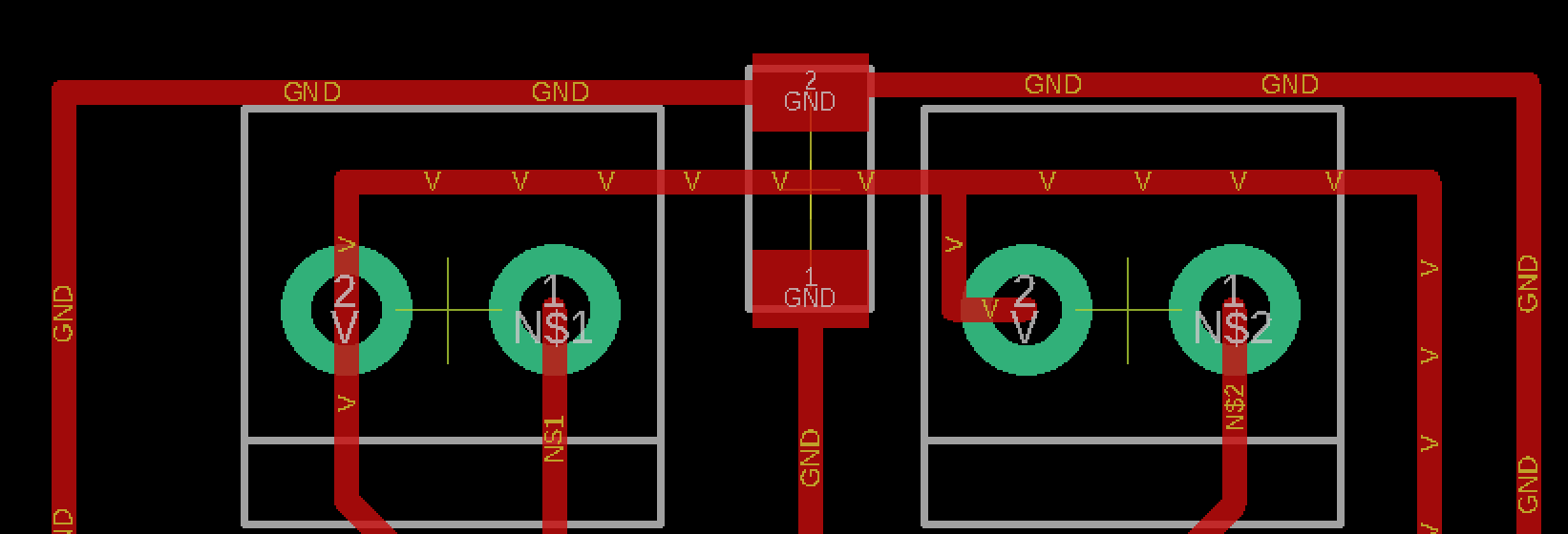
//Heater 1 pin = 5 (in attiny44) = 8 (arduino IDE)
//Heater 2 pin = 6 (in attiny44) = 7 (arduino IDE)
//Whater Pin = 2 (in attiny44) = 10 (arduino IDE)
Was quite easy to make... just a few lines of code and started to create steam...
The Adafruit Library does not work on Attiny44 because it takes more space than available (4K) but I found another one.. the
So after some research online I found a nice article DHT11 on ATtiny85 that recomended a different Library.. dht.h which can be found here -
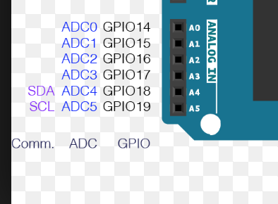
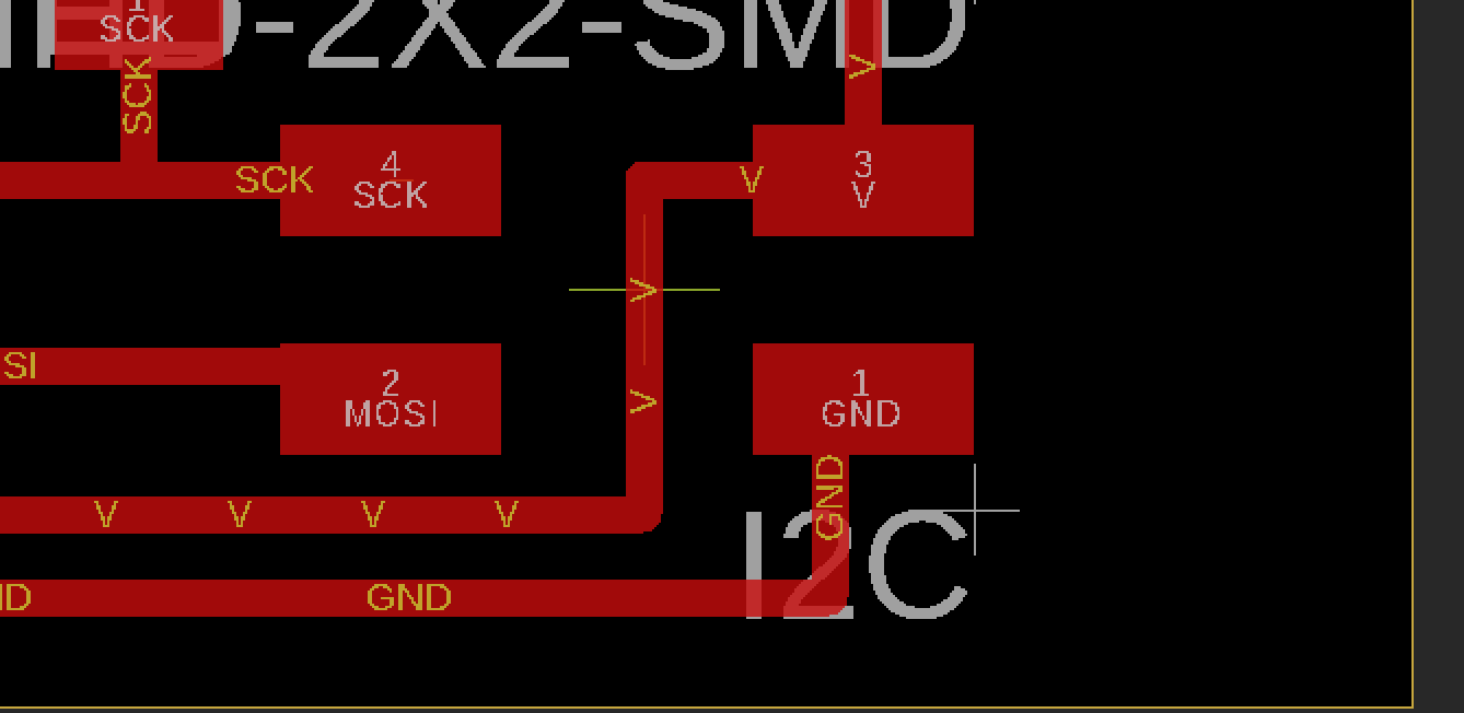
The Attiny pins for i2c are:
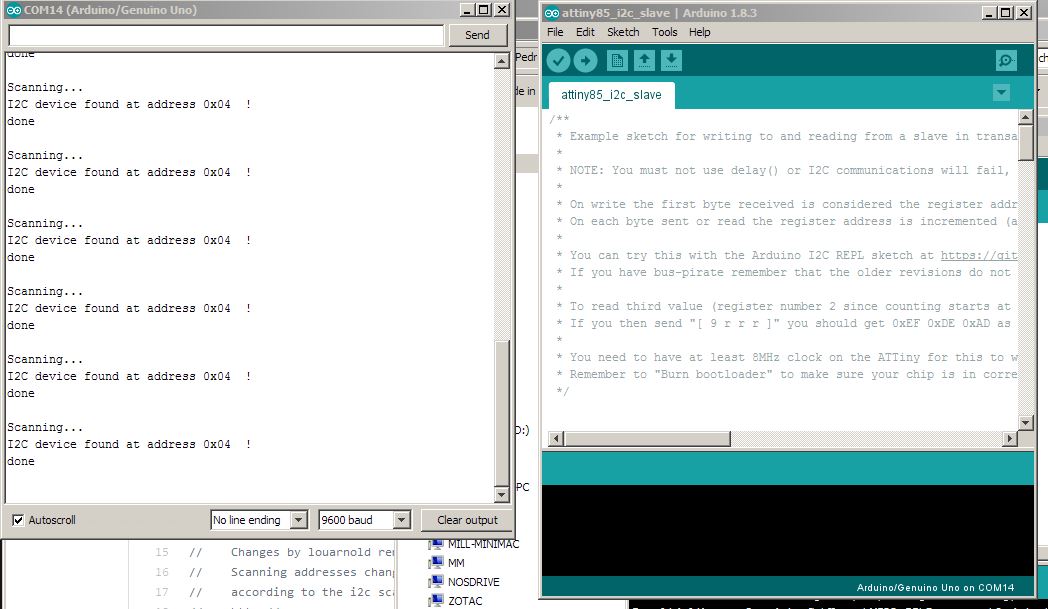
I'd use the TinyWireS library.. ambo/TinyWire which worked after desconnecting the ISP wires...:)
and to dectect the i2C of my board, i uploaded to Arduino UNO the SCAN sketch found here: tfeldmann/i2c_scanner.ino
Raspberry Pi is a series of small single-boar computers developed in the UK by Raspberry Pi Foundation to promote teaching of basic computer science in schools and in developing countries.
So to be usable I need to install an Operating System on it, and there's plenti to choose from, where the criteria should be the main purpose of the Computacional use...
10 Operating Systems You Can Run on Raspberry Pi in 2019 is a good article which lists the normal applciation fields of some of them...
By reading this and other articles, I decided to use Raspbian...
Since I'll be using a Raspberry Pi as main computer, and Raspbian as the Operating System
        Raspbian is a free operating system based on Debian optimized for the Raspberry Pi hardware.
        An operating system is the set of basic programs and utilities that make your Raspberry Pi run. However, Raspbian provides more than a pure OS: it comes with over 35,000 packages, pre-compiled software bundled in a nice format for easy installation on your Raspberry Pi.
The system must be configurated so to allow:
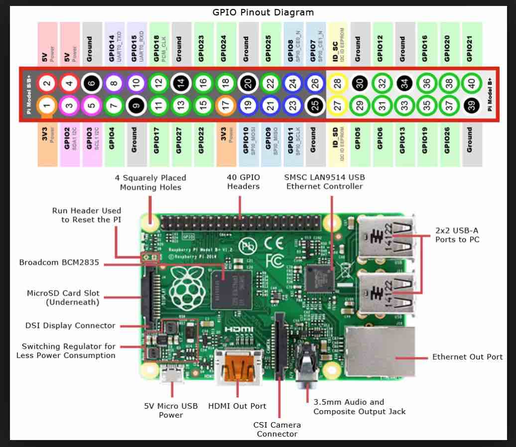
Raspberry Pi V23: pin 3 (GPIO02 - SDA) and pin 5 (GPIO03 - SCL)
this one uses i2C tooo
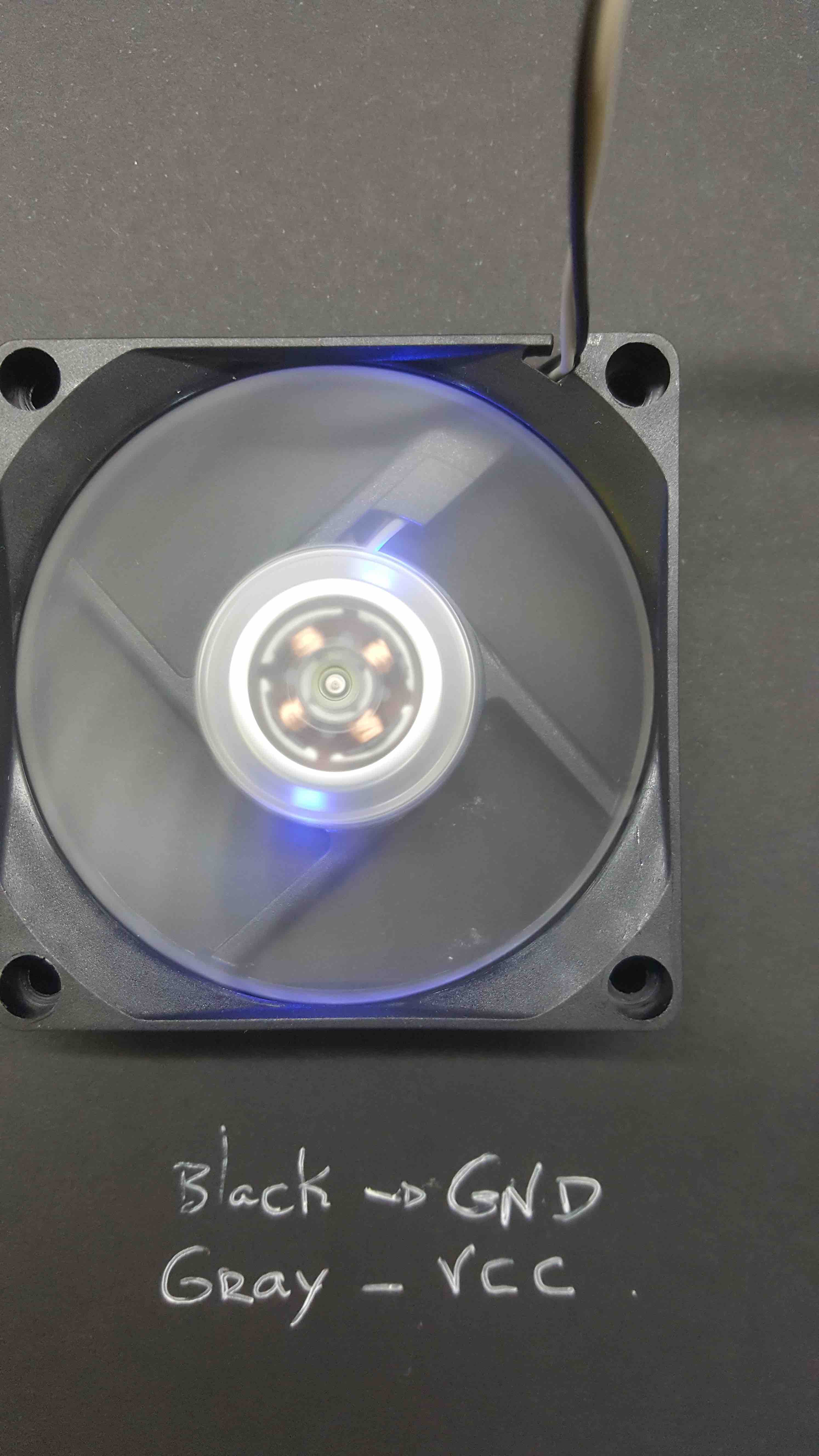
connected the fan GND to RAspberry GND on pin 6 and the Fan Green Wire to Raspberry pin 40 (GPIO21)
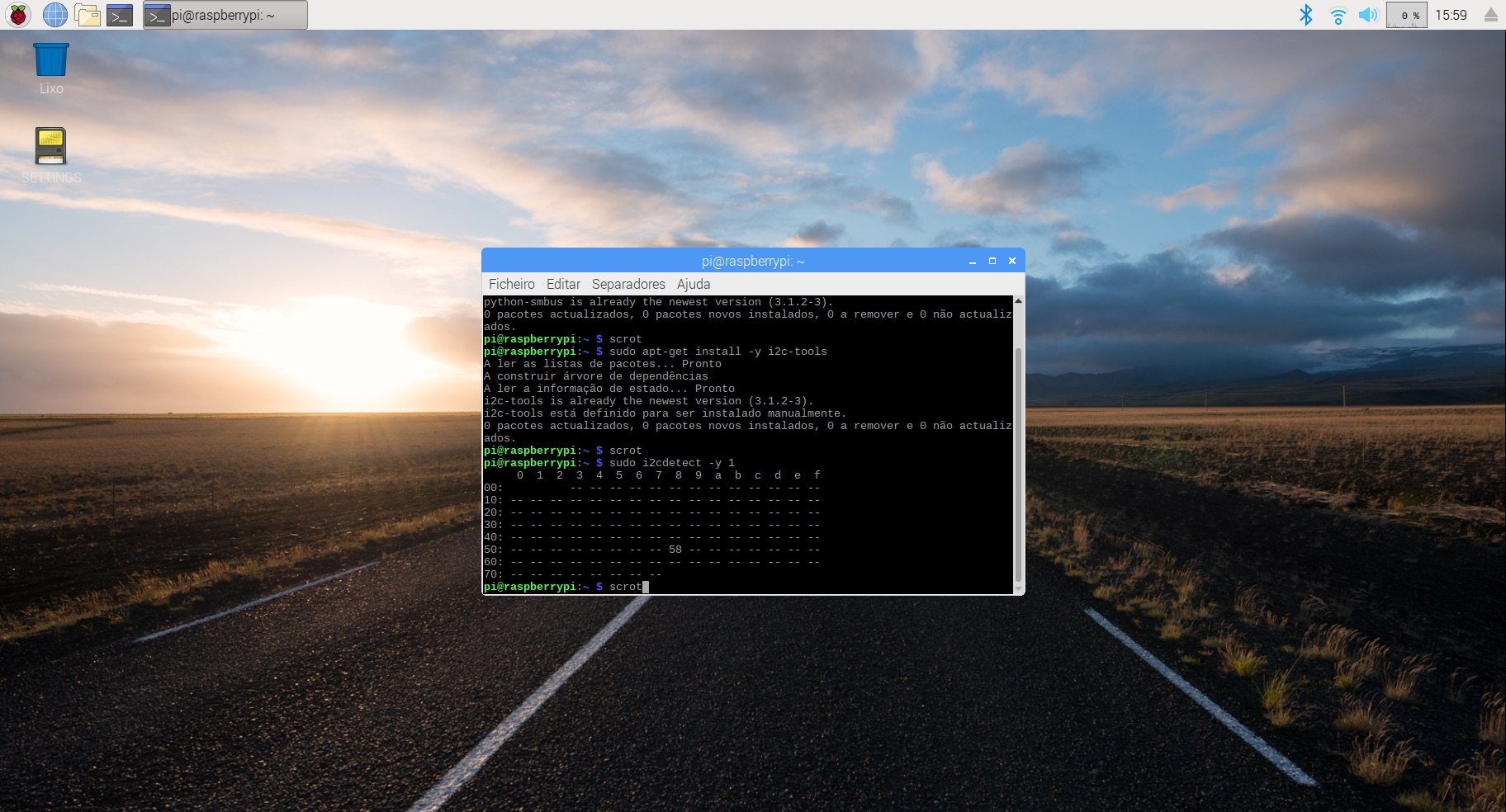
        sudo apt-get install -y python-smbus
        sudo apt-get install -y i2c-tools
        sudo i2cdetect -y 1
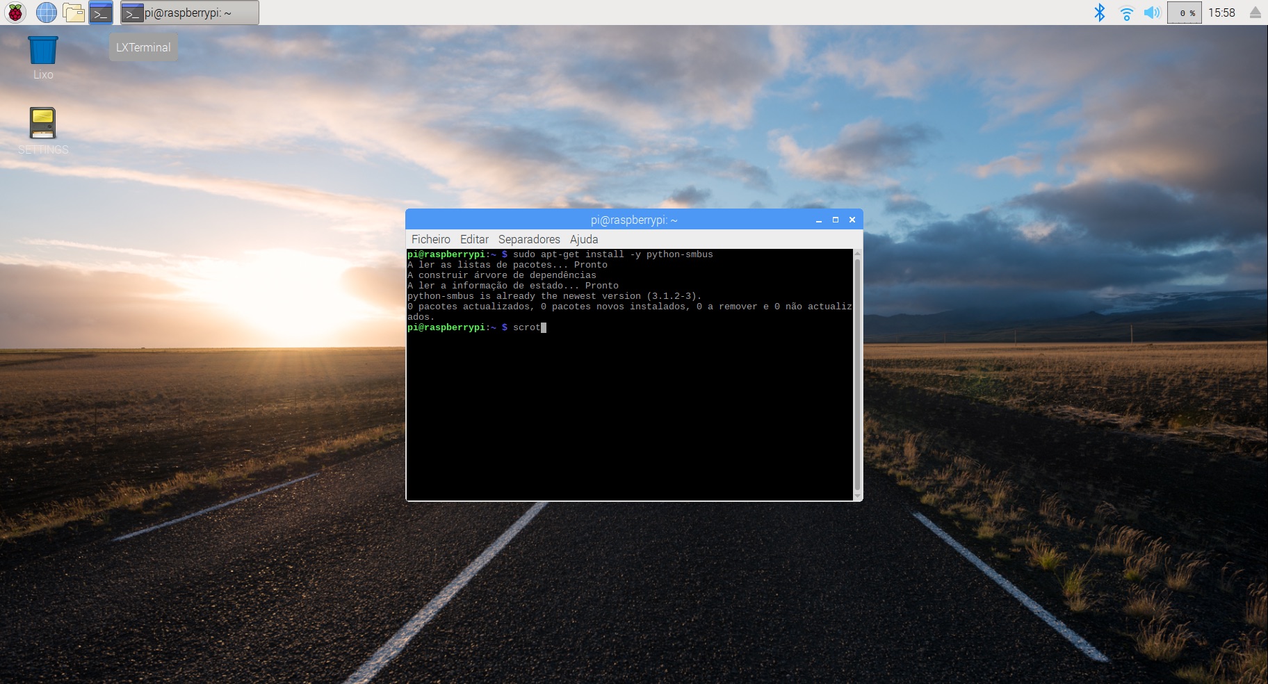

and it was installed the i2C and could see that the Grove Co2 Sensor was on address 58
chrome error due to Clock incorrect time..... sudo date -s "15 Jun 2019 12:58:00"
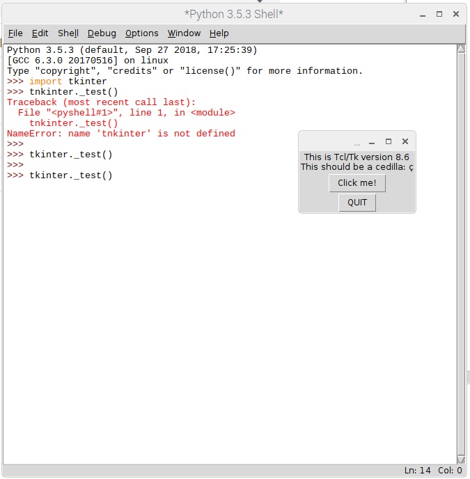
I assisted some videos in Fab Academy totorials and also used the practical advises of SparkFun Python GUI Guide: Introduction to Tkinter
One of the best parts of TkInter is that by default it's already installed as basic Python modules... here I'm testing its existence...
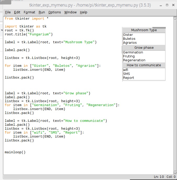
and trying the one Possible User Interface for fungarium...
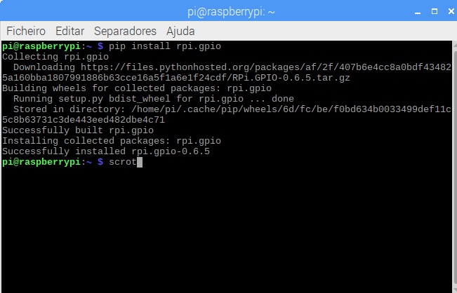
I need to control the fan using the GPIO... so I got to instal rp.gpio...
pip install rpi.gpio
in GPIO we can identify Pins in two different ways:
and here they are installed on the Raspberry Pi...
Now develop the Python-TkInter program to control the FAN...connected to BOARD pin 40
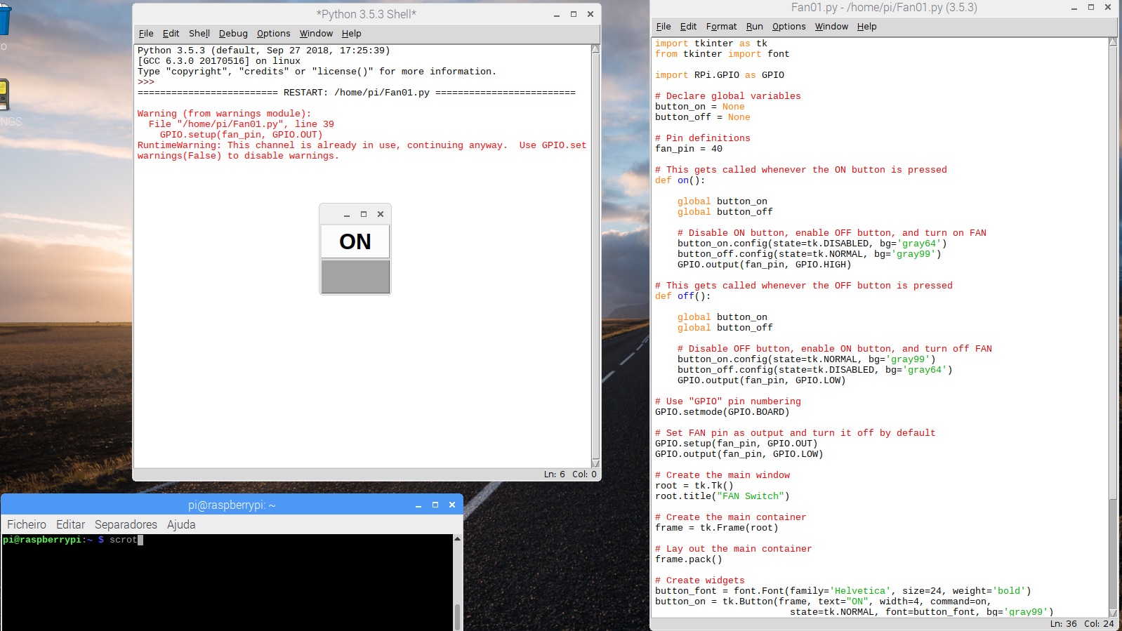
The code to control a Fan using a Tkinter Window is this one - Dowload Fan.py
but theres a problem... the Raspberry pin does not provide the enaugh current to make the fun run faster...it turns ON and OFF bur does not work faster... I'll need to solve this one after...
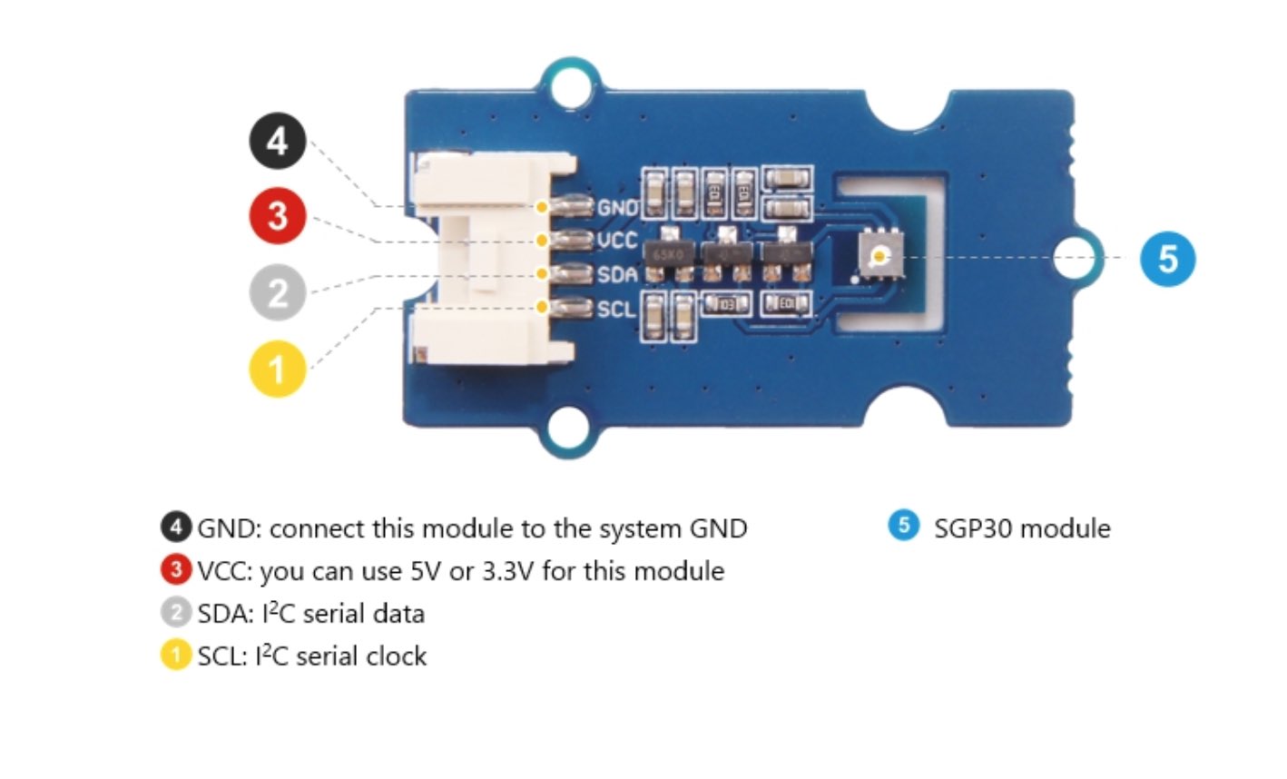
I connected the Grove sensor pins as fallows:
copied from SGP30 datasheet:
        The GSP30 supports i2c fast mode....in acordance with the NXP i2c-bus specification.
        All SGP30 commands anda data are mapped to a 16-bit address space.
        Additionally, data and commands are protected with a CRC checksum to increase the communication reliability.
        The 16-bit commands that are sent to the sensor already include a 3-bit CRC checksum.
        Data sent from and received by the sensor is always suceeded by an 8-bit CRC.
        In write direction it is mandatory to transmit the checksum, since the SGP30 only accepts data if it is followed by the currect checksum.
        In read direction it is up to the master to decide if it wants to read and process the checksum.
        The typical communicatoin sequence between the i2c master (my Raspberry Pi) and the sensor is described as follows:
            1. The sensor is powered up, communication is initialized
            2. The i2c master periodically requests measurement and reads data, in the following sequence:
                a. i2c master sends a measurement command
                b. i2c master waits until the measurement is finished, either by waiting for maximum execution time or by waiting for the expected duration and then poll data until the read header is acknowledge by sensor
            3. i2c master reads out the measurement result
I need to install the Python modules sgp30 and smbus2
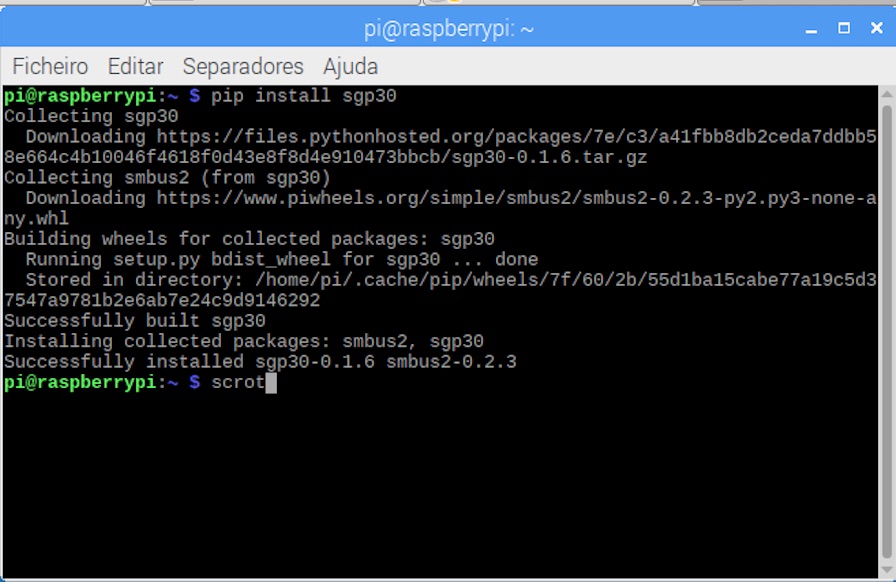
in order to use the Python library for SGP30...I needed to install SMBUS2 which was dificult..
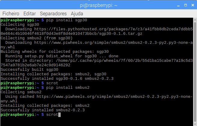
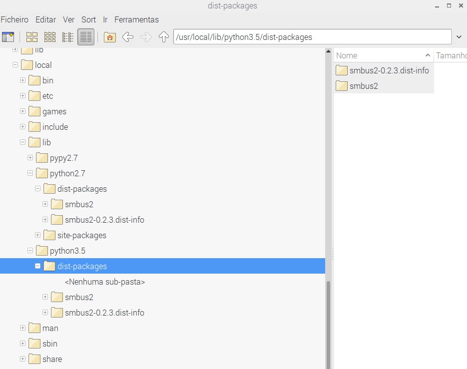
became a PROBLEM .. due the existence of 2 Pythons in my Raspbian, Python 2.7 on terminal and Python 3.5.5 on IDLE...and the above comand had installed the SMBUS2 on Python2.7... so made a HARD CODE...
Was because of that I'd hacked the System as shown...
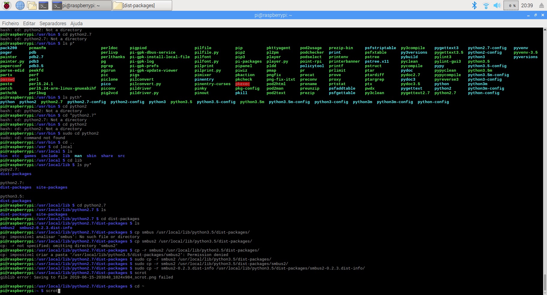
with this strategy I'd been able to have SMBUS2 also in Python3.5.3
But... even so I was not able to run the code... it was broken the SGP30 module, it was giving the error...
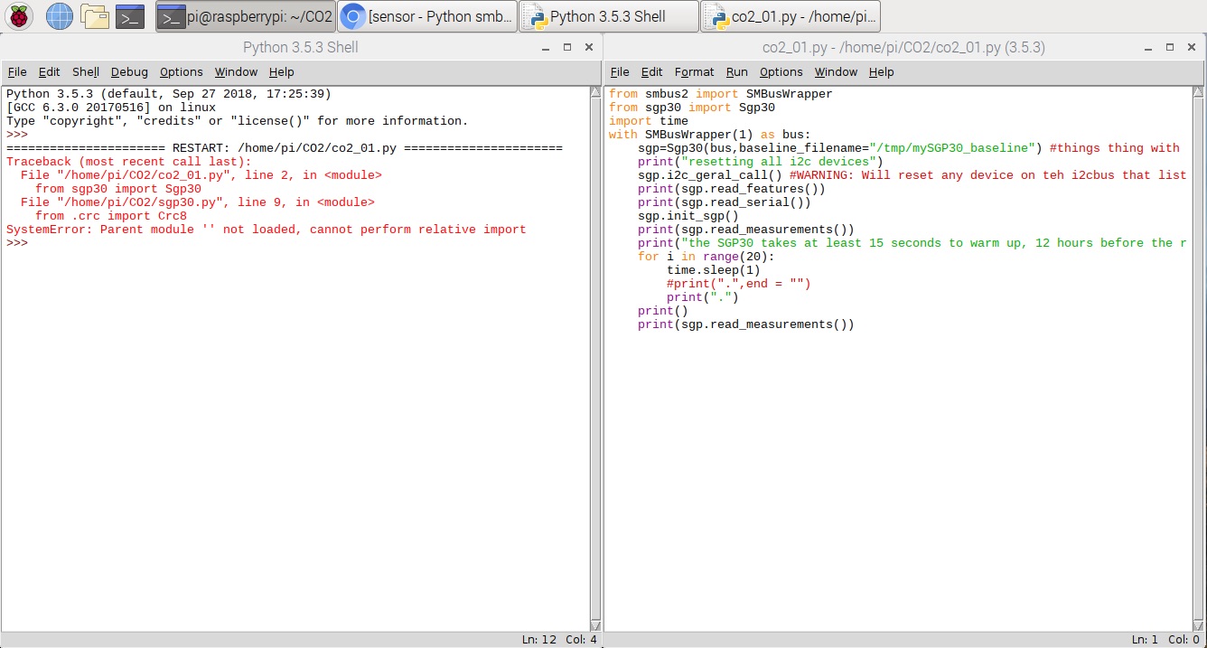
Went for another solution, that I could use... and found a nice one here: Python smbus lib with Sensirion SGP30 and here is my Co2 sensor working... HIHIHI
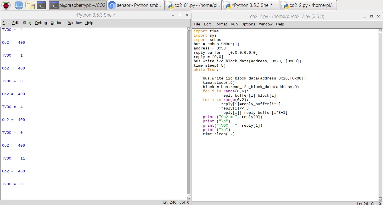
The code to have access to Co2 sensor through Python shell is here - Dowload Co2_02.py
←