Final project - Hardware
Back to Mónica Pedro ←main page ←Final Project
        Hardware  Architecture
        Functional  Specifications
         Parts  list technical specification
HW Architecture

Wikipedia definition of HardWare Architecture
In engineering, Hardware Architecture refers to the identification of a system's physical components and their interrelationships.
Often called a hardware design model, allows hardware designers to understand how their components fits into a system architecture and provides to software component designerss important information needed for software development and integration.
its is a representation because it is used to convey information about the related elements comprising a hrdware system, the relationships among these elements, and the rules governing the relationships.
It is a process because a sequence of steps is prescribed to produce or change architecture, and/or a design from that architecture, or a hardware system within a set os constrains.
It is a discipline because a body of knowledge is used to inform practitioners as to the most effective way to design the system within a set of constraints.
Continue reading a good book here: Chapter 1. An Introduction to Computer Architecture
Raspberry
 Image from Element 14 GOOD documentation
Hardware Specifications
- Processor: Broadcom BCM2837B0
- CPU: ARM 1176JZFS (ARM 11 w/ v6 core, floating pt @ 700MHz)
- GPU: Videocore IV GPU
- RAM: 1GB LPDDR2 SDRAM
- USB: 2 USB 2.0
- Network: Gigabit Ethernet, 2.4GHz and 5GHz 802.11b/g/n/ac Wi-Fi
- Bluetooth 4.2, Bluetooth Low Energy (BLE)
- Video out: HDMI
- Audio out: 3.5 mm jack
- SD Card Storage (Up to 32GB)
- Micro USB power
- Display Serial Interface Port (DSI)
- Camera Serial Interface Port (CSI)

Pi Camera NoIR MIPI CSI-2 Interface

Audio Output 3.5mm jack - is a electrical connector tipically used for analog audio signals.
I need to understand the audio jacks and found a nice documentation here: CUI INC...
Modularity
As professor Neil defends, we should design modular systems since they are easier to debug and enhance the life of the whole system by enaibling the possibility to change damaged modules, instead of the whole system...

So I thought on organizing the HW system according to the functionalities associated to each other, so we have the following Modules:
- Temperature and Humidity:
- Sensor: DHT11 Temperature and Humidity
- ..to trigger:
- ..... Heating Pad's
- ..... Water Atomization
- Attiny44 - Microcontroller to compute the Automation<
- i2c - networking protocol
- Carbon dioxide and Ventilation:
- Sensor: Co2 sensor
- ..to trigger:
- ..... Fan's - two fans
- Attiny44 - Microcontroller to compute the Automation
- i2c - networking protocol
- Image and Sound:
- Sensor: Raspberry Pi NoIR Camera
- ..to trigger:
- ..... Speakers
- ..... Camera with NoIR
- ..... IR led to support NoIR function of Camera
- Raspberry Pi 3 - Microprocessor to provide User and HW interfaces..
- i2c - networking protocol with other modules
HW design
connecting the modules, being the last two mo
Module 1 - Temperature and Humidity, I will need to have on the board:


- Attiny44
- DHT11 - 4 pins/PAD's?????
- 10K resistor connected to DHT11 data pin and Microcontroller VCC - note online
- Grove - Water Atomization V.01 - 2 pins
- Heating Pad's -
- 2 MOSFET, N Channel, 30V, 1.7A, 500mW, SOT-23
- i2C pins
considerations when designing the board in eagle:
- PB2 as PWM - which could be used for Heating pad 01
- PA6 as PWM - which could be used for Heating pad 02
- Water Atomization needs a Digital pin - PA1
- DHT11 needs a Digital - PA0
finally on Eagle made this board
 Download Eagle Schematic
 Download Eagle Schematic
Module 2 - Carbon dioxide and Ventilation, I will need to have on the board:

- Attiny44
- Co2 - 4 pins
- Fan - 2 pins
- i2C pins
- need to figure out how to handle two i2C connections in this board
Figuring out how to handle i2C in attiny44 so that it behaves as Raspberry slave and as Co2 board Master...
When looking for experiences online and found quite a few...
The question is that to do i2C in a Attiny44 we need to use:
- Pin PA6 (A6) = SDA + MOSI
- Pin PA4 (A4) = SCL + SCK
So looked online for situations where Attiny44 has two i2c busses, one as Slave and other as Slave
AVR Freaks... ATTiny with both I2C Slave and I2C Master separate buses - Use HW I2C for the slave since a software slave is difficult.Use any other 2 pins to implement software master.
Now this one is quite practical...
Arduino Forum... 2 I2C buses on an ATtiny85 (Read 154 times)... "I2C protocol can be implemented on any 2 GPIO pins. It's easier to simulate a master versus a slave, but they're both possible. There are plenty of "bit-bang" libraries which can do this for you (like mine)".
... it seams that there is also a Library to implement i2cBiy-Bang on any AVR...
bitbank2/BitBang_I2C
... The purpose of this code is to provide a simple C library which can bit-bang the I2C protocol on any 2 GPIO pins on any system. The I2C protocol doesn't require any special functionality of the pins beyond standard GPIO features....
Module 3 - MAIN as Master, and connecting to Camera and Speakers:

- Raspberry Pi 3
- Raspberry pi Camera Noir
- Speakers
- i2C Wires
- IR led... would be important if want to use NoIR filter of this camera
Power Consuption

| Part |
Voltage |
Current |
| Heating Pad |
5V |
0,74 A |
| Misty Maker |
5V |
0,4 A |
| DHT11 |
5V |
0,3 mA |
| Co2 |
|
5V |
| Fan |
5V |
0,26 V |
| Total |
|
~1,4 |
| Raspberry Pi 3 |
2 output pins of 5V |
1,5 A |
Hardware Specifications
| Sensor |
Incubation value reference |
frutification value reference |
Part reference |
| Humidity |
80% humidity or more |
80%-85% |
|
| Temperature |
23º - 25º |
18º |
|
| Moisture |
since moisture = soil (temperature & humidity) the value references are the same as above |
xxxxx |
|
| pH |
Mycelium: 7 (or 6) |
Fuiting: 7-8 |
|
| Image |
detect dimensions |
detect colors |
|
| CO2 |
mushroom spaw - 10 000 ppm to 20 000ppm |
mushroom grow - 800 ppm to 1 500 ppm |
new mycelium begins grow >= 5 000 ppm |
| Actuator |
Function |
Value refences |
Part reference |
| Air Flow |
circulate air inside/outside |
80%-85% |
|
| Air Filter |
control organismes and particles |
HEPA |
|
| Camera |
take photos |
Computer vision SW to analise evolution/state of the living fungui |
Raspberry Pi NoIR Camera V2 |
| IR led |
move Computer Vision set (camera & IR led) to new positions - survilance of Fungui |
|
|
| Motor (Computer vision set movement) |
move to new positions - monitor Fungui |
should shot light for NoIR photos... not always!? |
|
| Sound |
Sound waves (music or other frequencies)
- frequencies of 0.1 kHz to 1 kHz and intensity of 70 dB to 80dB |
attention to sound wave propagation - materials for walls |
SPEAKER MINIATURE 2.5" 8OHM - Speaker, Mini, 60 mm, 0.5 W, 8 ohm, 260 Hz to 4 kHz |
| Temperature |
Heat or Refresh the environment |
Could be made out of a 3D printer heating BED |
|
| Humidity |
enhance the quantity of water in interior air or substract |
a few water drops over time or Mist machine |
|
Parts list and characterization
- DHT11 Humidity & Temperature Sensor DHT11 Humidity & Temperature Sensor
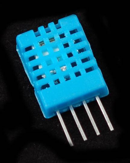
- 3 to 5V power and I/O
- 2.5mA max current use during conversion (while requesting data)
- Good for 20-80% humidity readings with 5% accuracy
- Good for 0-50°C temperature readings ±2°C accuracy
- No more than 1 Hz sampling rate (once every second)
- Body size 15.5mm x 12mm x 5.5mm
- 4 pins with 0.1" spacing
- ____ pin 1 - VCC - red wire Connect to 3.3 - 5V power. Sometime 3.3V power isn't enough in which case try 5V power.
- ____ pin 2 - Data out - white or yellow wire
- ____ pin 3 - Not connected
- ____ pin 4 - Ground - black wire
- ____ ++++ Adafruit recomends to place a 10 Kohm resistor between VCC and the data pin, to act as a medium-strength pull-up on the data line.... Arduino has built in pullups we can turn on but they're verey weak, about 20-50K...
- ____ ++++ ++++ Adafruit adds that:
- Analog pH Sensor / Meter Pro Kit For Arduino

- Soild Moisture Sensor

- This sensor can be used to detect moisture of soil, or plant water level.
- Interface: Octupus Electronic Bricks
- Uses two probes to pass current through the soil, and then it reads that resistance to get the moisture level.
- ____ More water makes the soil conduct electricity more easily (less resistance), while dry soil conducts electricity poorly (more resistance).
- Specification:
- _____ Power Supply: 3.3v or 5v
- _____ Output Voltage signal: 0-4.2v
- _____ Current: 35mA
- NO DATASHEET .. not been hable to find it...
- Co2 sensor-
- Temperature / Heating
- Humidity
- Pi Camera NoIR specifications

- Still resolution: 8 Megapixels
- Video modes: 1080p30, 720p60 and 640 × 480p60/90
- Linux integration: V4L2 driver available
- C programming API: OpenMAX IL and others available
- Sensor: Sony IMX219
- Sensor resolution: 3280 × 2464 pixels
- Sensor image area: 3.68 x 2.76 mm (4.6 mm diagonal)
- Pixel size: 1.12 µm x 1.12 µm
- Optical size: 1/4"
- Sensitivity: 680 mV/lux-sec
- Fixed focus: 1 m to infinity
- Focal length: 3.04 mm
- Horizontal field of view: 62.2 degrees
- Vertical field of view: 48.8 degrees
- Focal ratio (F-Stop): 2.0
←


 for which I found only the Textile Datasheets: Ultra Heating Fabric download and Non- Carbon Fiber Electrical Heating Textile Download