Mechanical and Machine Design Week 15
Introduction
For the mechanical and machine design weeks, we had to cover the following tasks:
- Mechanical design week: design a machine that includes mechanism+actuation+automation
- Machine design week: Actuate and automate our machine.
- Document our group and individual contributions
Machine concept
- The machine concept that we decided on was intended to be fun and different than the usual CNC machine concepts common for this week's projects. My Fab Academy classmate Nada and I decided to build an M&M candy sorting machine based on color.
- During the research phase of the project, we found several design concepts of color sorting machines. The one that inspired our mechanism design the most was this one:
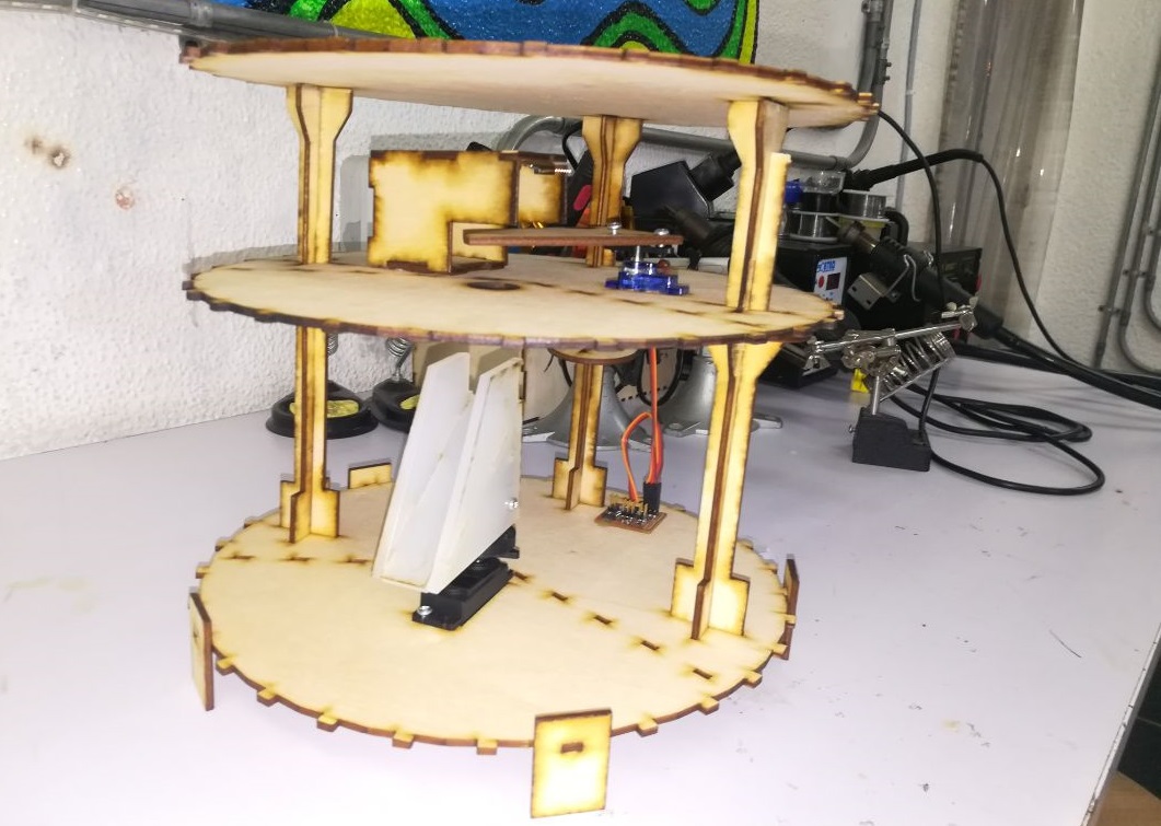
- The basic concept is: the machine is arranged vertically into two levels, the upper level is where the color sensing takes place, then the candy is transfered to the lower level where the sorting happens based on color. Nada drew some nice free hand sketches for the intial concept, while I decided to visualize that concept by developing a rough animation for the mechanism using Fusion 360.
Mechanical Design: CAD
- My individaul contribution to the mechanical design was designing and fabricating: the end affectors, sensor box and coupler. While Nada was responsible for designing the chassis and frame of the machine.
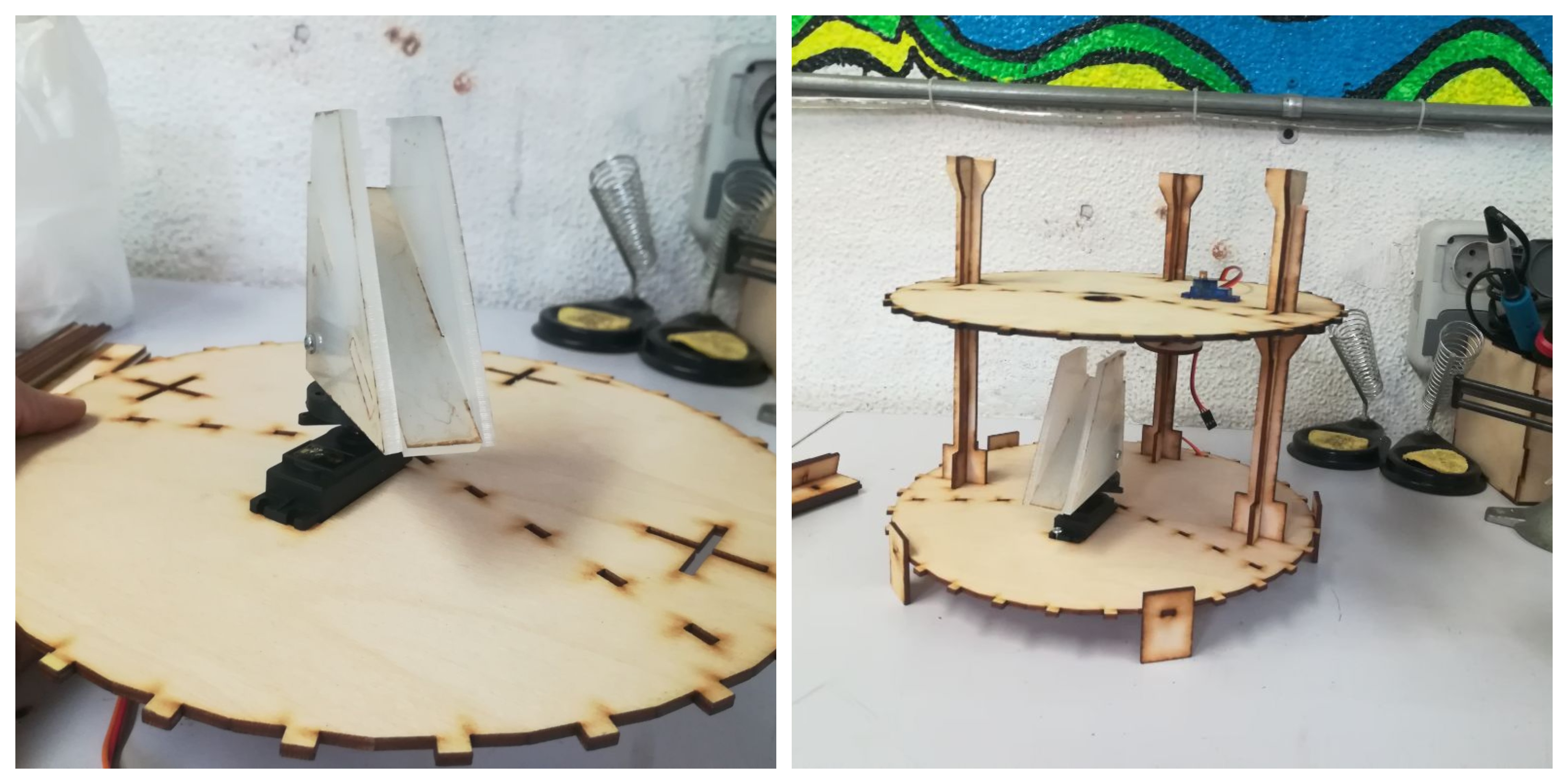
- But when it comes to design I usually like designing and prototyping by hand first before using any CAD software. So I developed some parts of the mechanism using foam clad to be able to estimate the dimensions and visualize the entire mechanism in 3 dimensions.
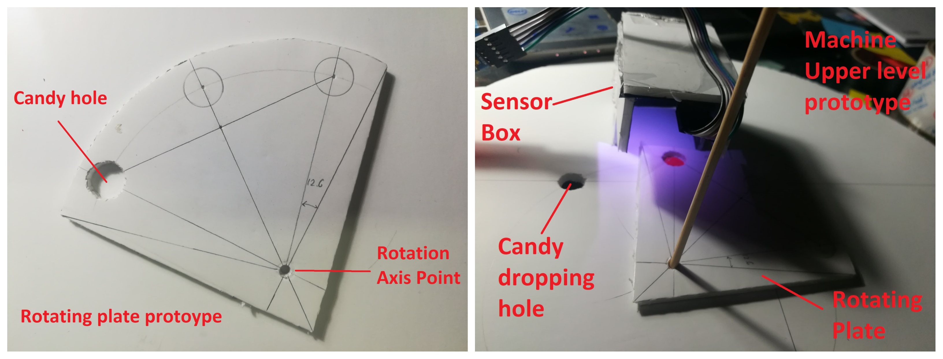
- Then, I designed the parts parametrically using Fusion 360.
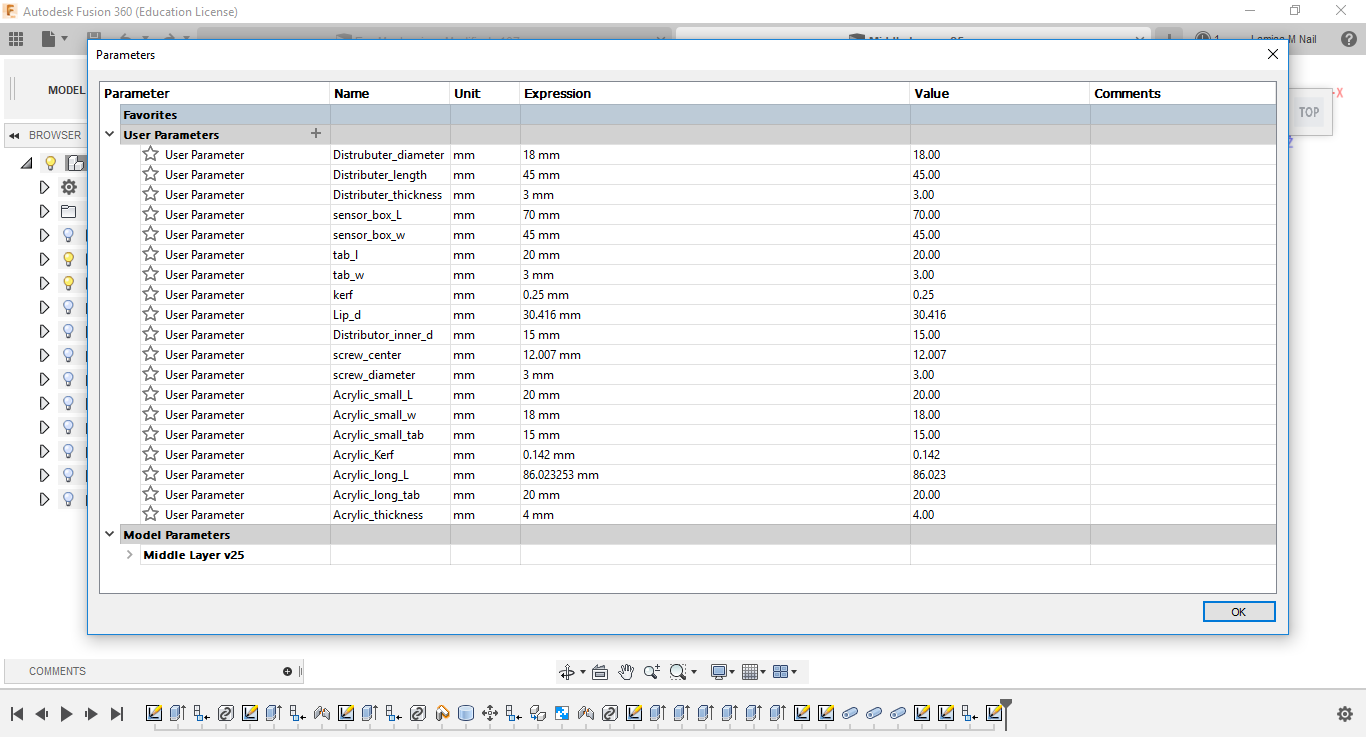
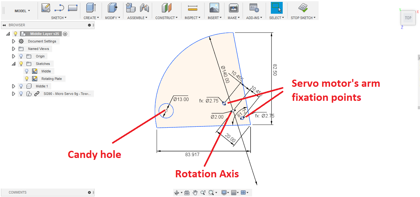
Part 1: Rotating Plate (The first end affector)
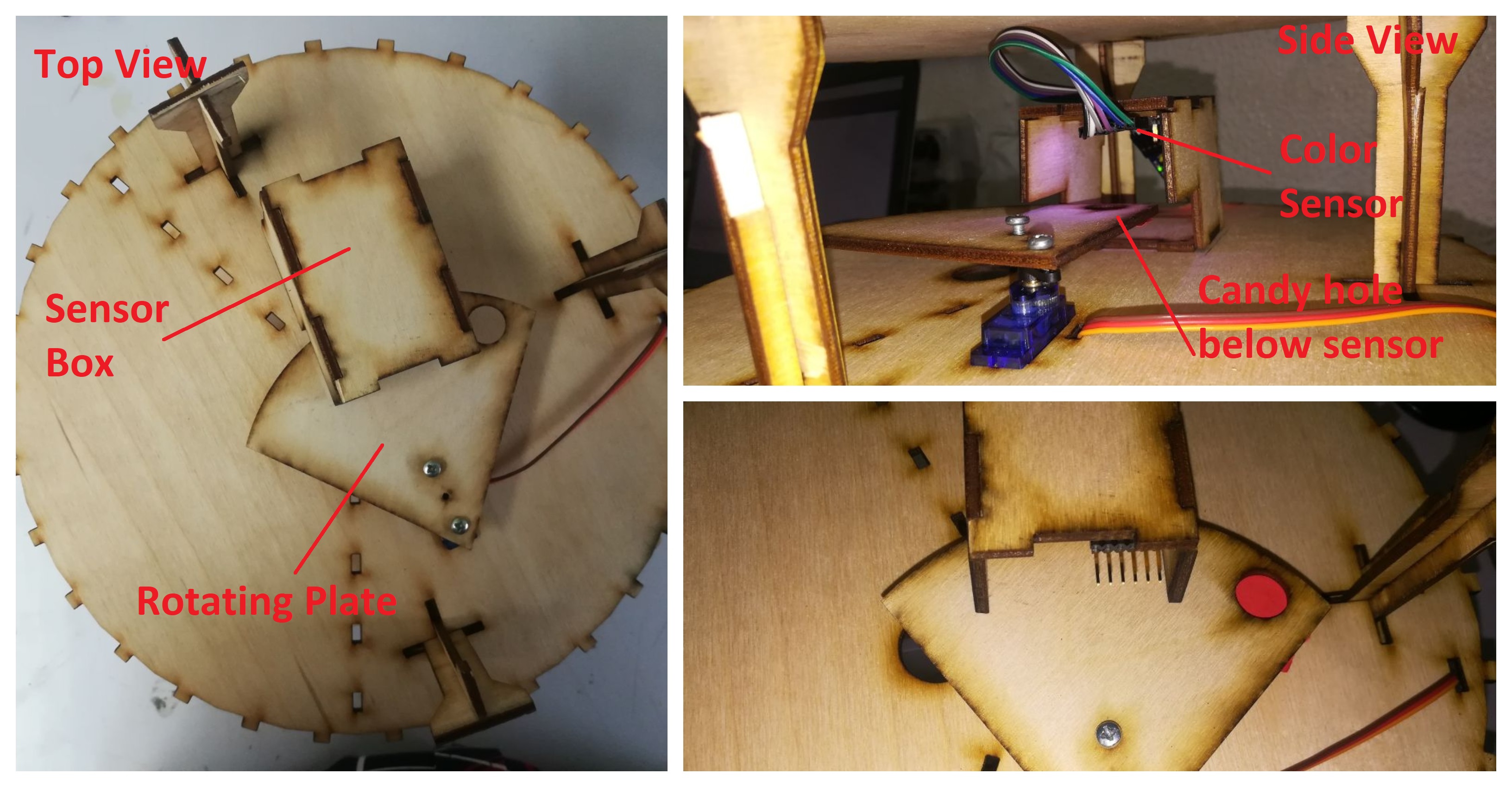
- Function: it is the part that receives the candy and deliver it to the sensor. Then, from the sensor to a hole where the candy drops to the second end affector.
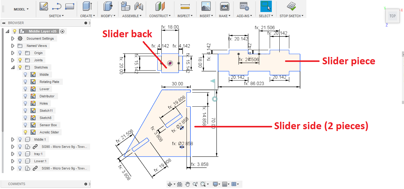
Part 2: Candy Slider (The second end affector)
- Function: it is the part that receives the candy from the first end effector and distribute it to the correct container based on its color.
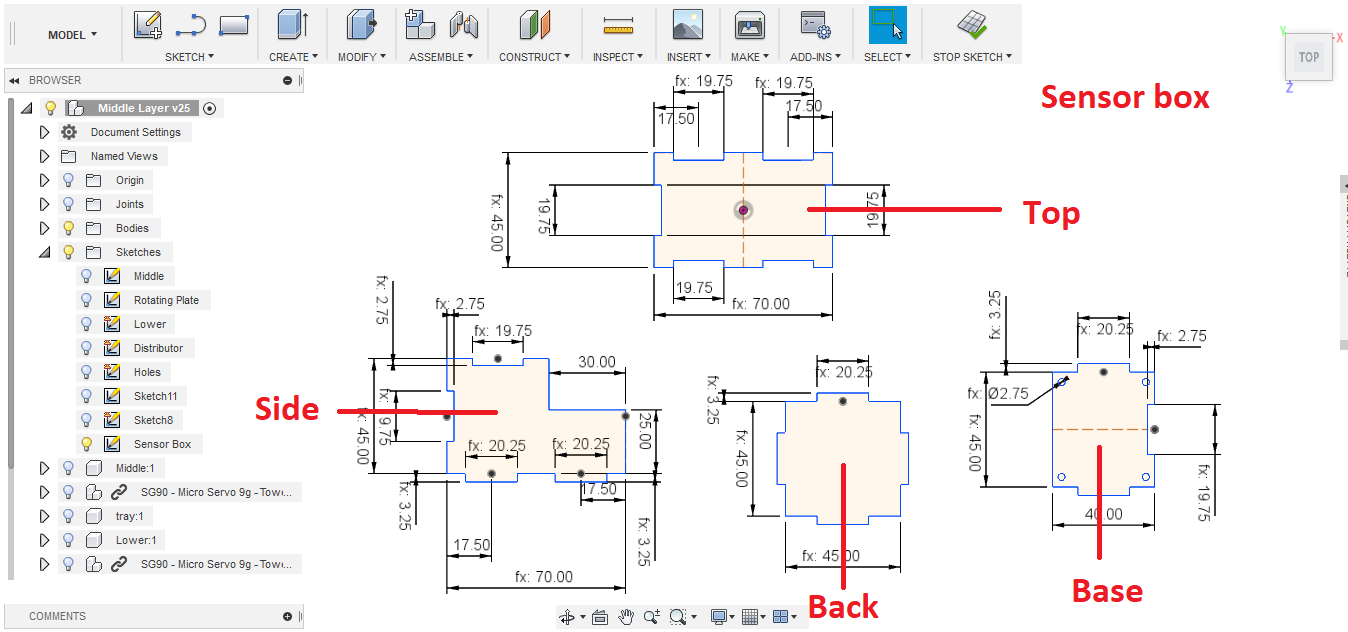
Part 3: Color Sensor box
- Function: It is a casing and shield for the color sensor from external light sources as much as possible to avoid causing flactuations in sensor readings.
Part 4: Coupler
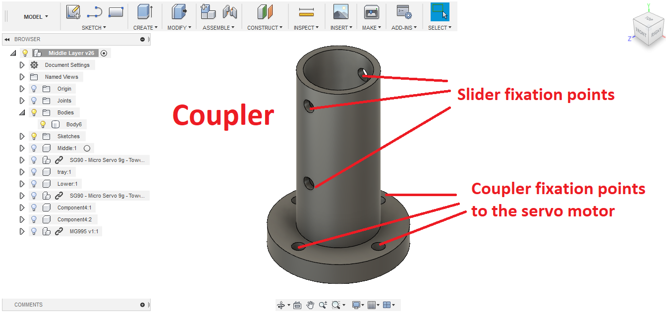
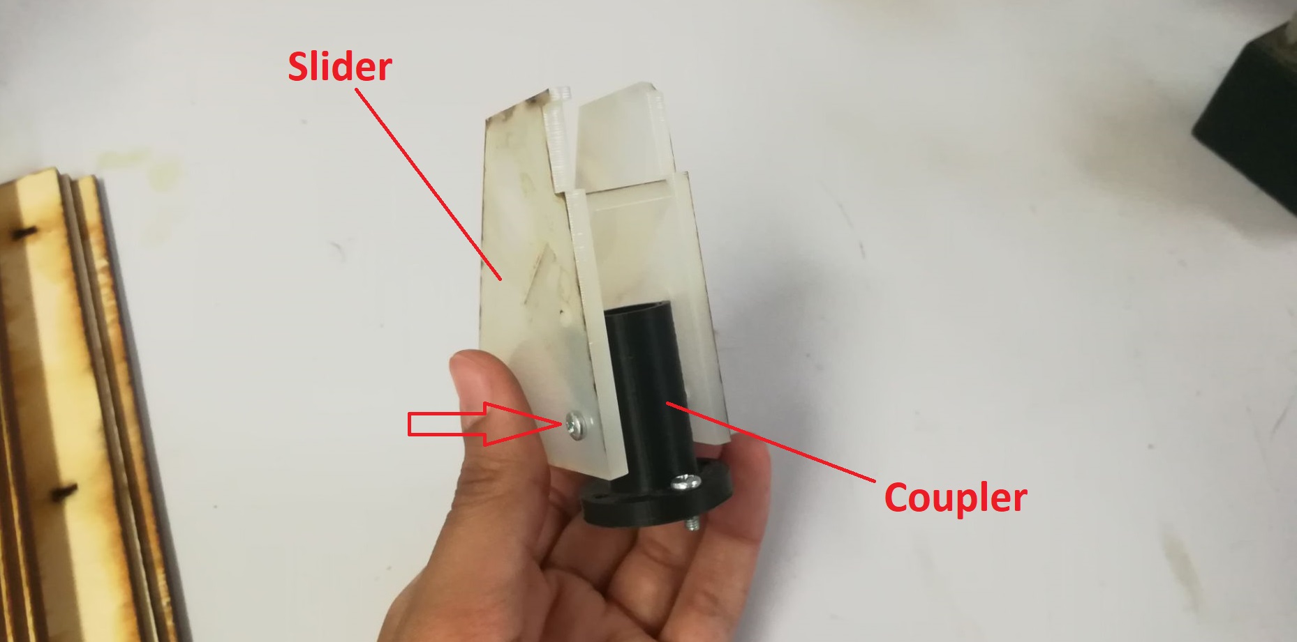
- Function: It serves as a connector between the candy slider and the servo motor.
Mechanical Design: Fabrication & Integration
Parts 1 & 3
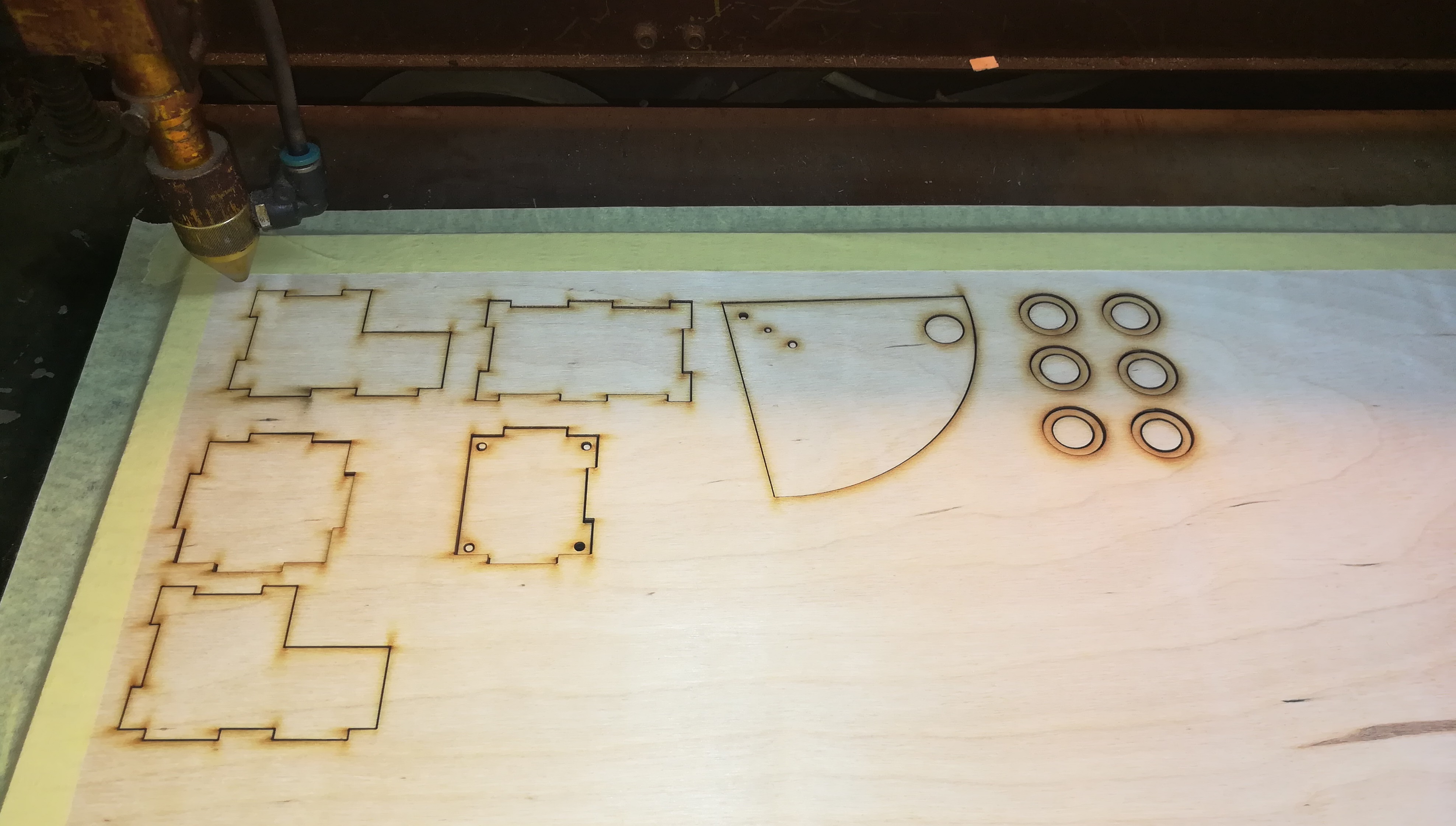
- Fabrication technique: Laser cutting
- Material: Plywood (3 mm)
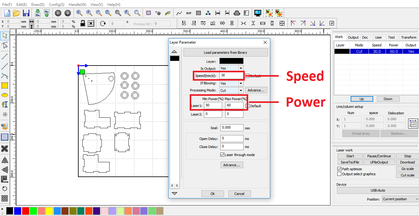
- Imported the DXF files into LaserWorksV6, set the power to 60 and speed to 30.
Part 2
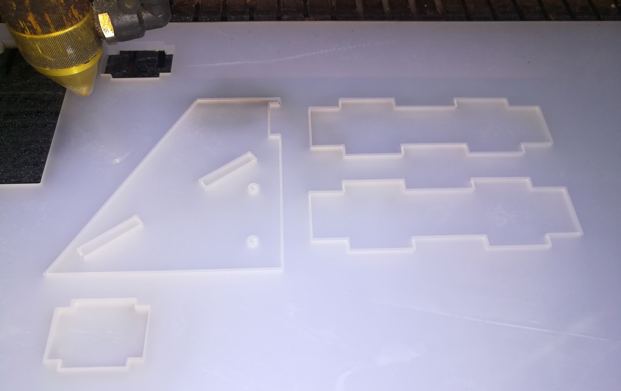
- Fabrication technique: Laser cutting
- Material: Acrylic (4 mm)
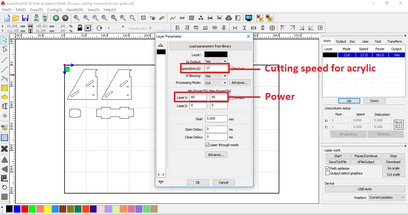
- Imported the DXF files into LaserWorksV6, set the power to 60 and speed to 17.
Part 4
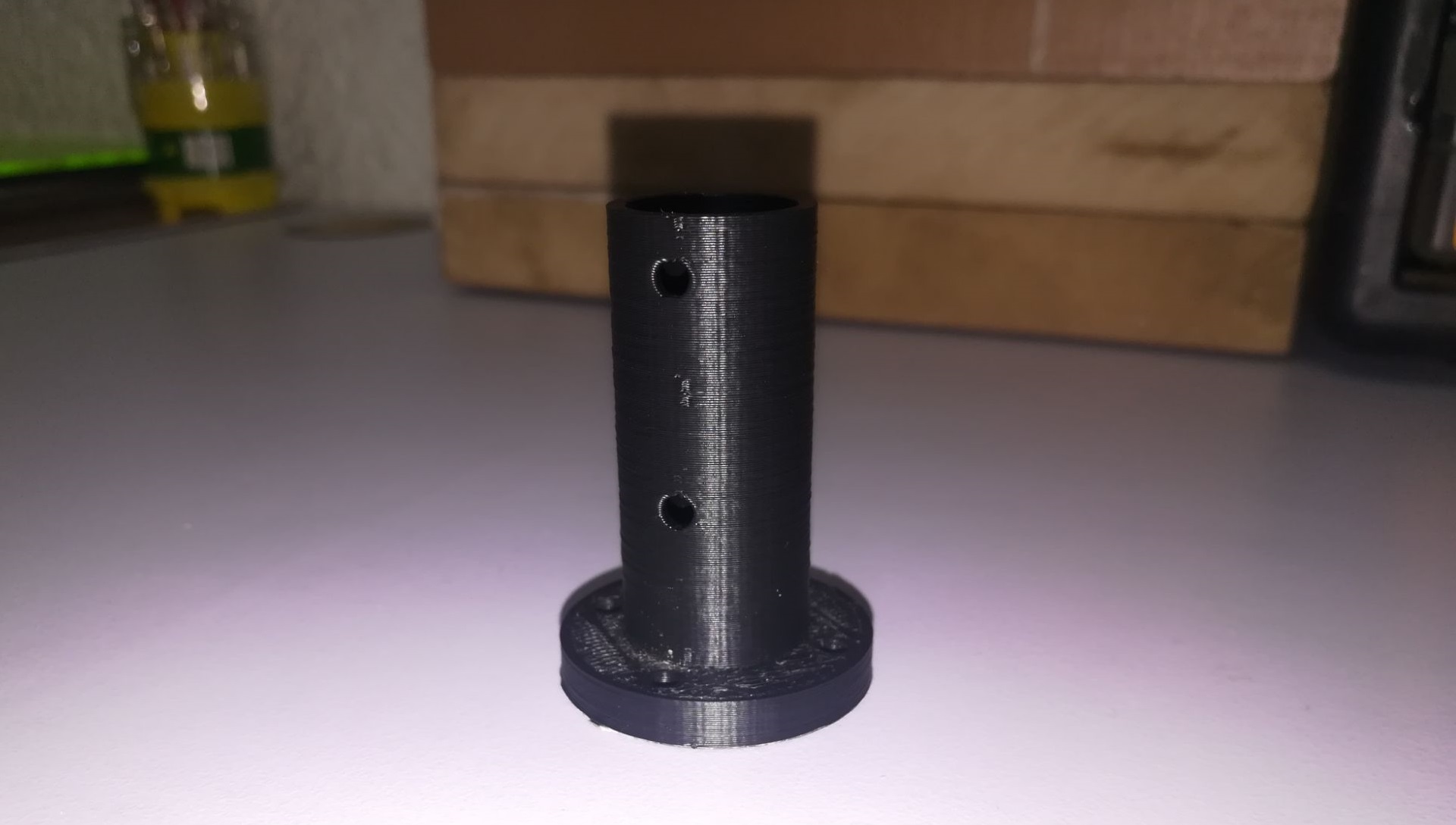
- Fabrication technique: 3D printing
- Material: ABS (black)
- Imported the DXF file into CURA 4.0, sliced it at a layer height of 0.15 mm.
Integration
Machine Design: Embedded Programming & Mechanism Demo
- My individual contribution in the machine design was to operate and test the machanisms, both in the upper and lower levels, and hopefully automate the mechanism based on sensor readings.
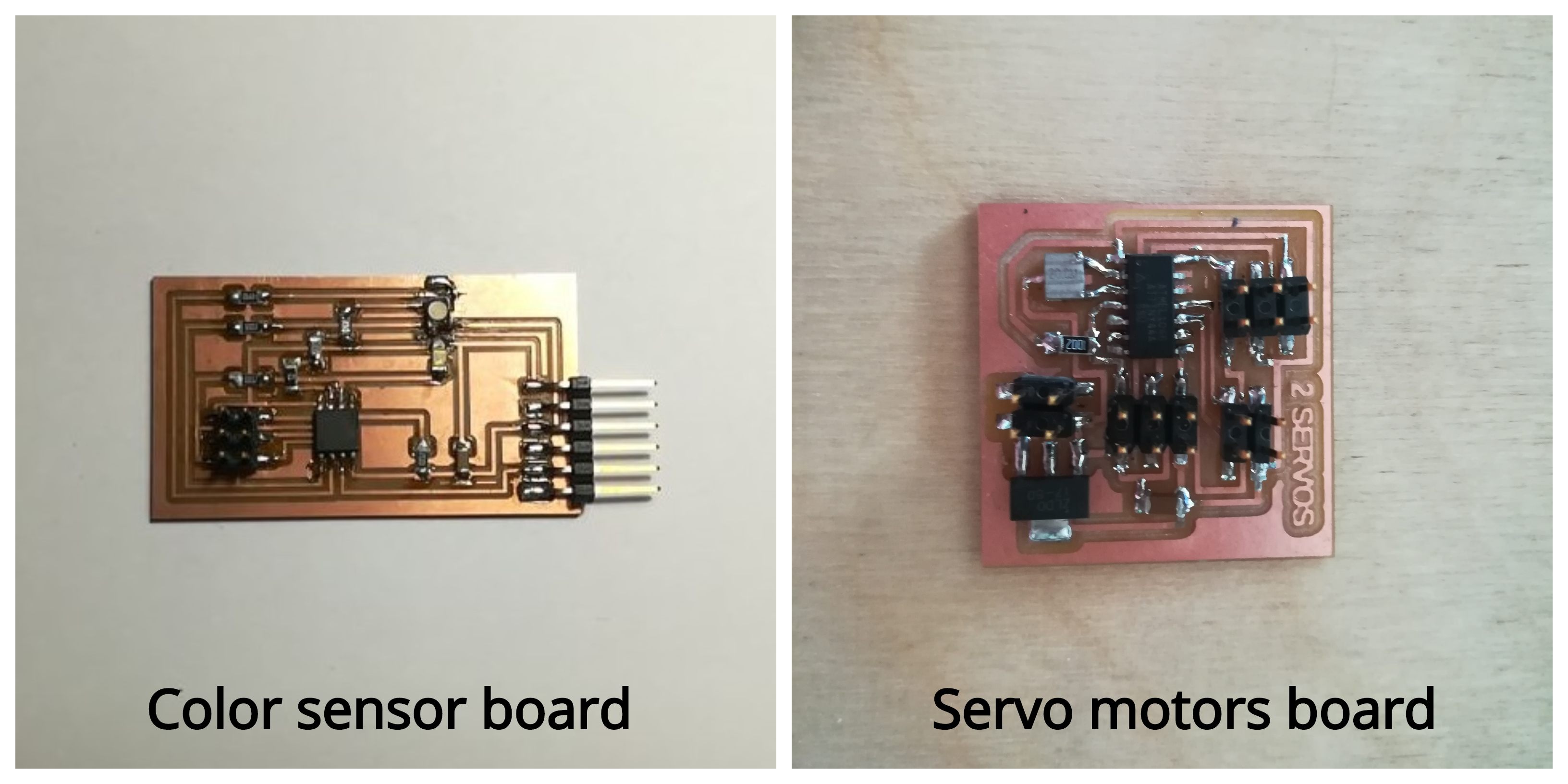
- Microcontroller boards: I worked with the servo motors board that was designed and fabricated by Nada . While we used the color sensor board that I designed and fabricated in the the input devices week.
Servo board programming & testing
- I soldered the servo board, connected it to the FabISB programmer and started with making fuse, to command the attiny44 to use the external crystal.
- I started with testing the servo mechanisms I needed to calibrate the upper level servo motor to move to 3 specific angles: the first angle at the funnel position where the M&M candy is supposed to drop. The end affector stops at the second angle, to expose the candy to the sensor, and finally at the third angle the candy slot in the end affector aligns exactly above the opening where the candy will drop down to the second end affector
- To figure out these angles, it wasn't a straight forward task I had to change the PWM and notice where the servo will angle will end up. This is because the FiTec FS90MG microservo motor's angle range is 120 degrees not 180 degrees, so the straight forward mapping of the PWM: 1ms to 0 degrees, 1.5ms to 90 degrees and 2ms to 180 degrees was not possible.
- The final angles of the desired position for servo motor at the upper level of the machine were: 0.7 ms for the intial position were the candy is collected, 1ms for the second position at the sensor box, and finally 1.6 ms for the final position at the hole through which the candy will be dropped to the lower level.
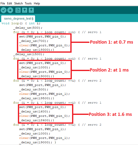
- Notice the rotating plate (end affector 1) as it rotates with the 3 predefined angles
- For the candy slider (end affector 2): I used 2 test angles at PWM of 0.5 ms and 1ms
- Notice the candy slider (end affector 2): it starts at the first position which is kind of in the middle of the range, the end affector rotates back to this angle after distributing the candy. The second test position is the hypothetical position of the container where the candy is supposed to be dropped based on its color.
Sensor board programming & testing
- M&M candy comes in various colors, and I need to "teach" my microcontroller to recognize these colors and take actions based on it.
- But before this, I need first to record the readings of the color sensor in response to the exposure to candy colors. These readings will be used later as decision making conditions that will operate the machine mechanism.
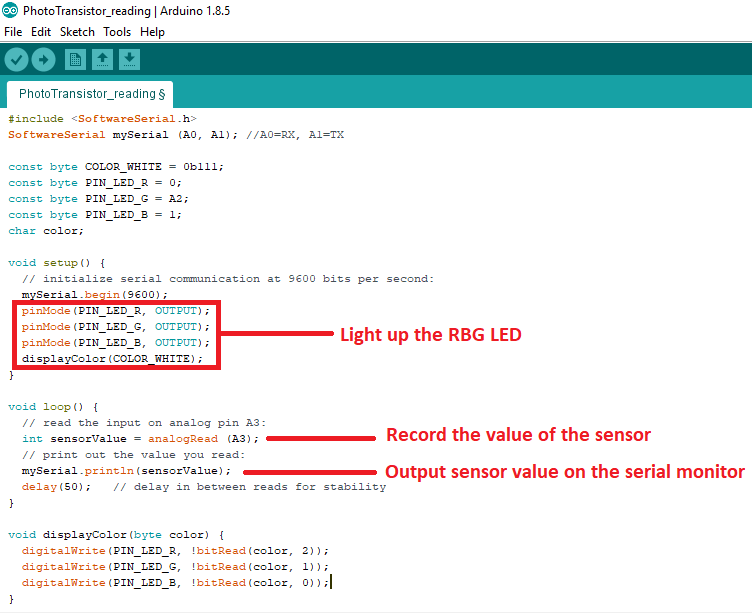
- I uploaded the following code to the color sensor board. The code simply light up the RGB LED, some of this light is absored and the rest get reflected from the colored surface with a wavelength very specific to this color.
- This wavelength is recorded by the phototransistor on the board, turning it into an analog electrical signal which is then recorded in a variable named "sensorValue".
- sensorValue is then sent via serial communication to the serial monitor. This value changes based on color as I mentioned, so we simply write down these values by hand to use it later in the code that will control the mechanism.
- I explained the color sensor reading process and its results in detail in the input devices week.
Communication (Failure)
- Now comes the challenging task, to open a communication channel between the color sensor board and the servo board.
- As an intial step in the process, I tried to make serial communication with the servo board through an FTDI module connected to a computer.
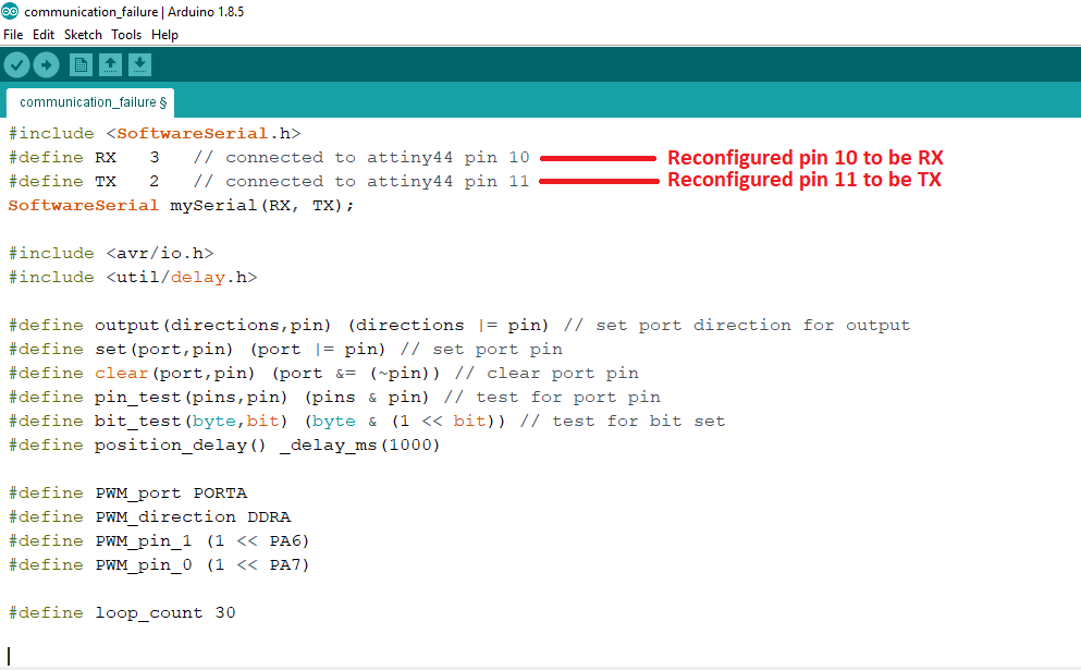
- As a first step, I reconfigured pins 10 & 11 on attiny44 (Arduino pins 2 & 3 respectively) to be used for software serial communication.
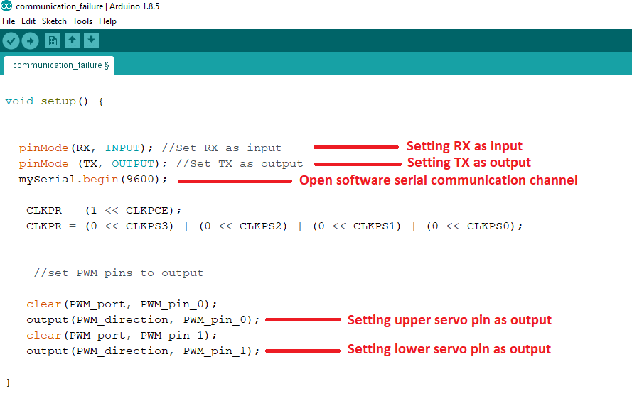
- Then, open the software serial channel, and set the RX pin mode to receive (input), while TX pin mode to transmit (output)
- Once the communication is open, the servo board receives the character that has been entered and compare it to the one in the if condition, when true the servo motor is set to rotate at 0.5 ms and a "received" confirmation message is sent to the serial monitor. When false, a rejection message "not received" is sent to the serial monitor.
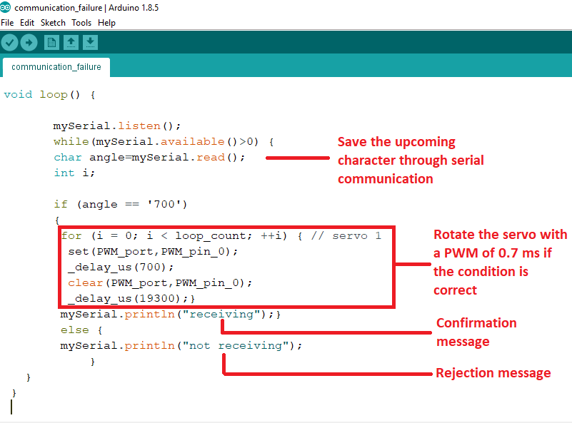
- The problem is that even when the if condition was supposed to be true, the servo didn't operate and the rejection message "not receiving" was sent to the serial monitor.
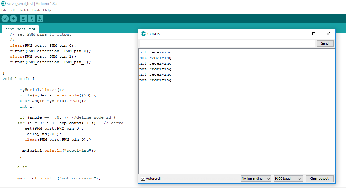
- The problem here was unclear, but we had a couple hypotheses in mind. First, the problem could be that we were sending a character '700' rather than a character "A", which didn't translate well through serial communication, and the condition was always false. There was another hypothesis, that serial software library doesn't work well with attiny44 leading to communication failure.
- At this point we decided to leave the servo microcontroller board all together and use another microcontroller. We started with an Arduino board, then shifted to Satshakit as the final microcontroller board for the project.
Operating the machine using Satshakit: Group work
- Considering that Nada and I both designed and used Satshakit for our final projects, it was an obvious alternative for the servo board.
- At this stage, Nada and I decided to start the process with reading the sensor value again, but this time we brought the sensor down closer to the colored object for the sensor to be able to detect the color directly with no interference from the environment.
- Next, we picked 4 to 5 vivid colors to perform the test with, red, blue, yellow, green and pink. Next, inserted the colored cards one by one and recorded the readings when the sensor got exposed to the colors.
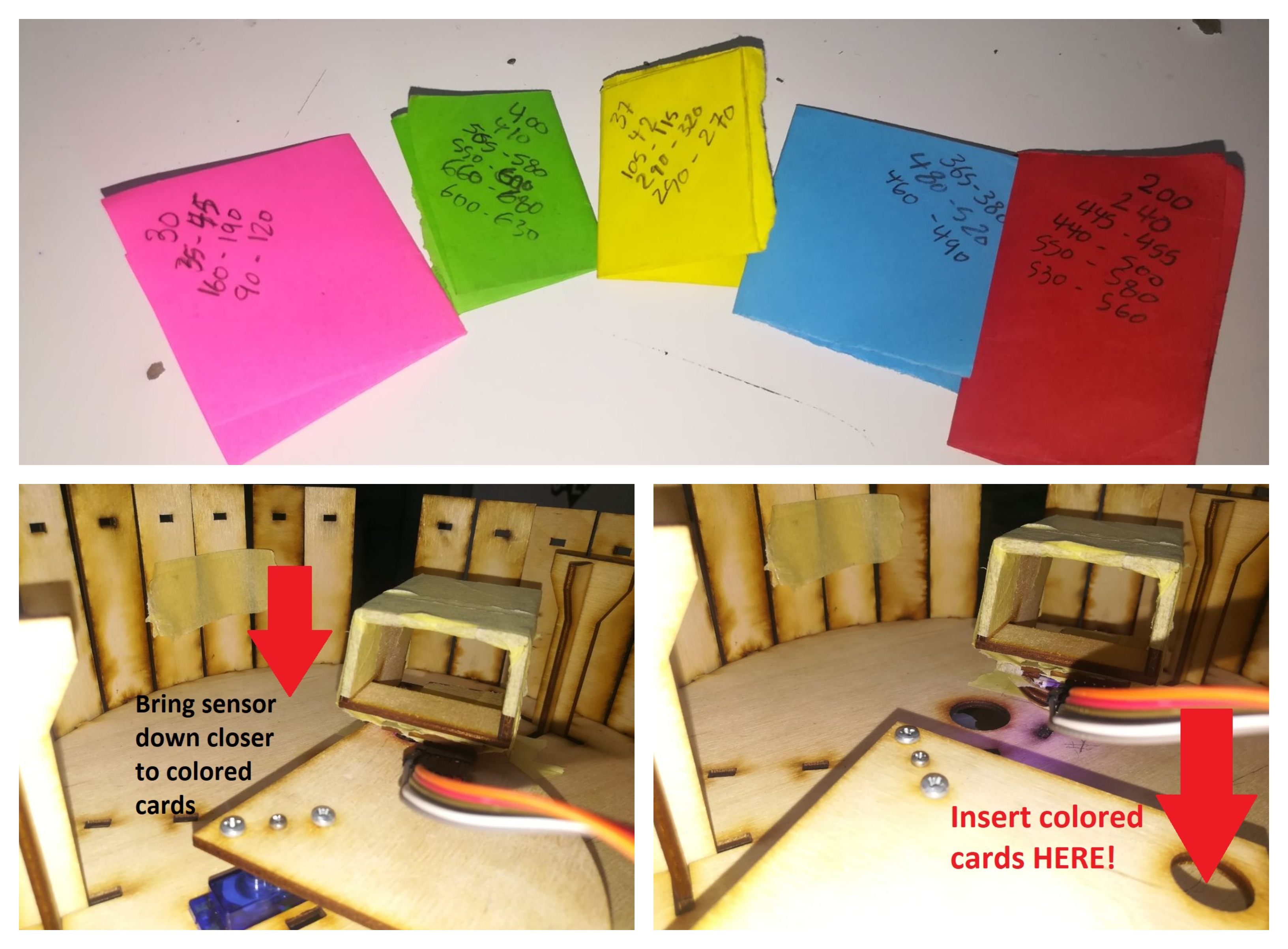
- These were the reading results: Blue range: from 440 to 515, Green range: from 580 to 650, Red range: from 520 to 590, Yellow range: from 250 to 300, and Pink range: from 60 to 170.
- Next we assigned a unique character to each color range, and programmed the sensor board to send that unique character on the RX serial pin for each colored card it reads.
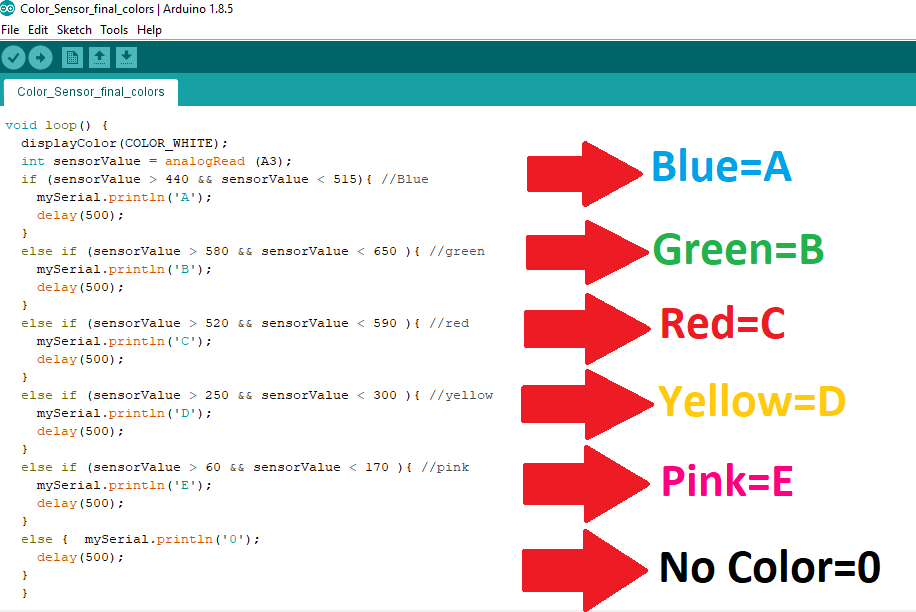
- The video below demos how the sensor outputs a character for each color it reads on the serial monitor:
- The next step is to feed these characters into Satchakit microcontroller via serial communication, which will operate the servo motors according to the character.
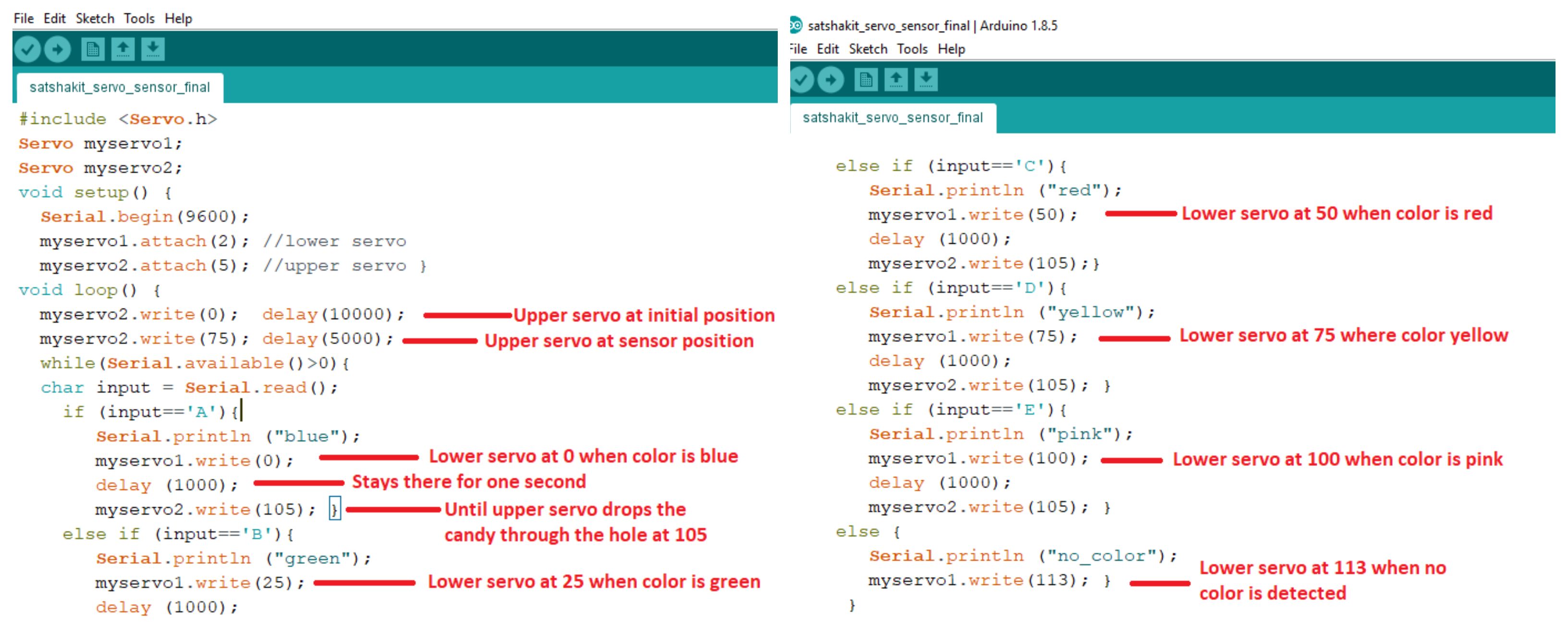
- We calibrated the angles of the upper servo motor as follows: an angle of 0 degrees as the intial position of the rotation plate, 75 degrees as the sensor position, and 105 degrees is the dropping hole position.
- For the lower servo motor, each color/character was assigned a unique position/angle. Blue at 0, green at 25, red at 50 and yellow at 75.
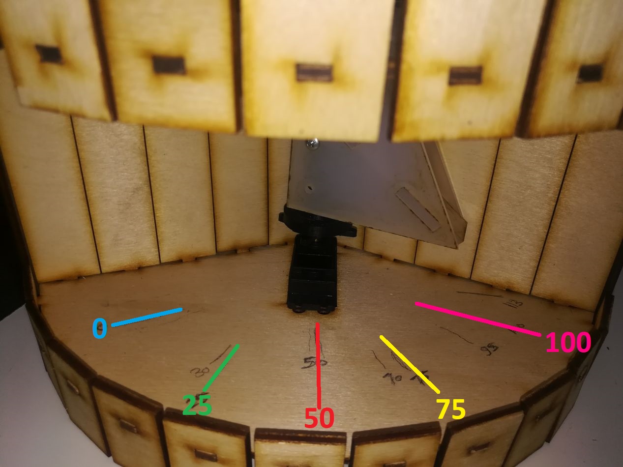
- The code is simply a series of if-conditions, when one is true, upper and lower servo motors will go to the underlying angles.
- When all the conditions are false the lower servo will go to an angle of 113 degrees.
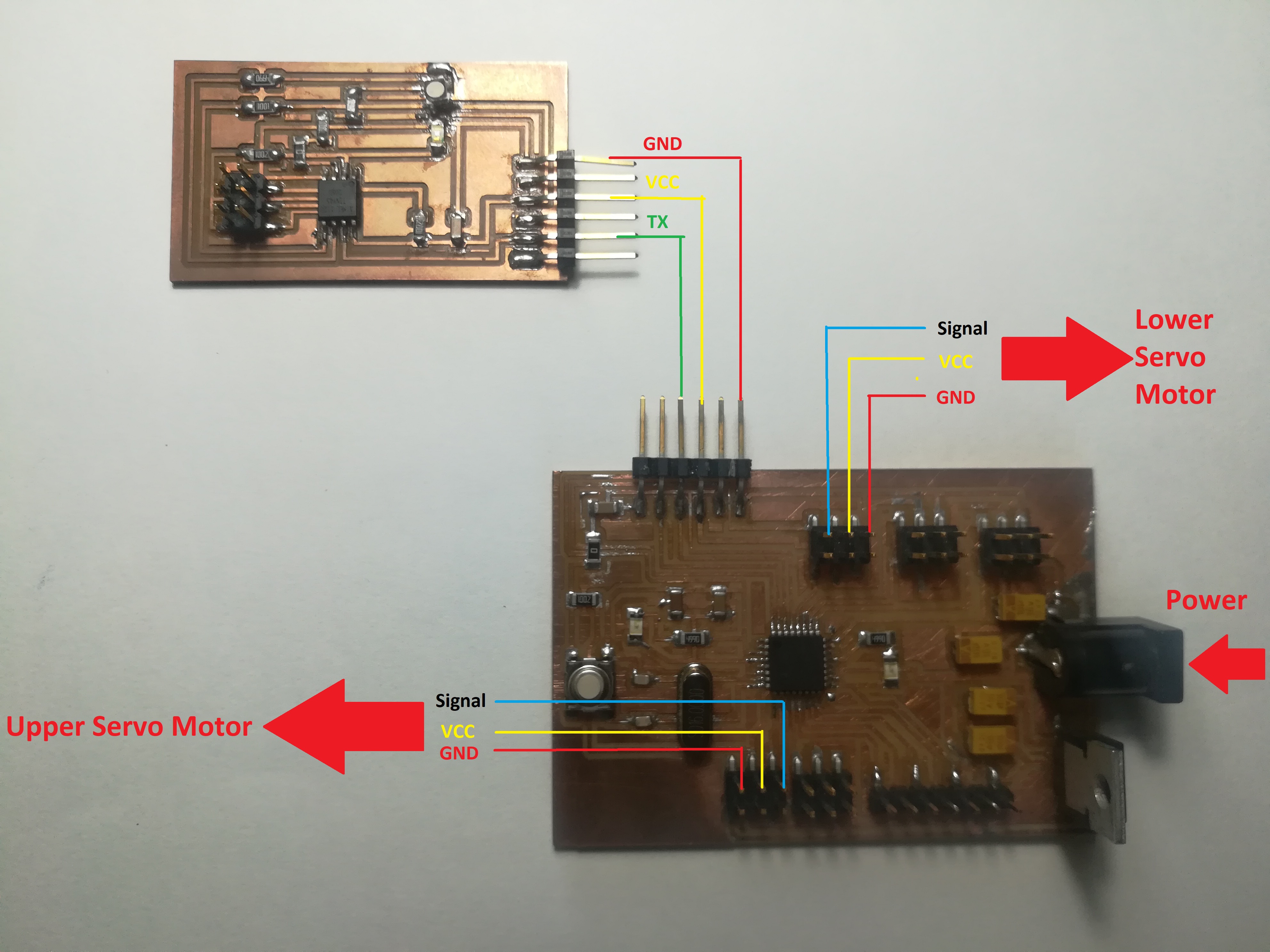
- The boards and servos were wired according to the diagram below:
- A final demo of the machine sorting colors:
Design Files