Output Devices Week #12
Introduction
This week we have two main assignments:
- Individually: Add an output device to a microcontroller board you've designed, and program it to do something
- In a group: Measure the power consumption of an output device
Output Device #1: RGB LED
- The first output device I worked with this week is the RGB LED, I started working with the RGB LED during the input devices week, I used it as part of the color detection board and for this specific purpose I used it only used only the white color. For this week's assignment I worked with different colors as I will explain below.
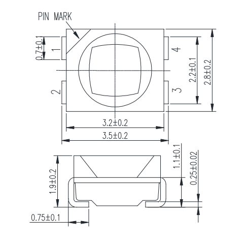
- The RGB LED is simply a 3 in 1, Red, blue and green LEDs in one package, by activating more than one LED at once, we can simply output different colors. The RGB LED's (PLCC4) data sheet indicates that the LED has 4 pins, 1 pin for each color and 1 common anode.
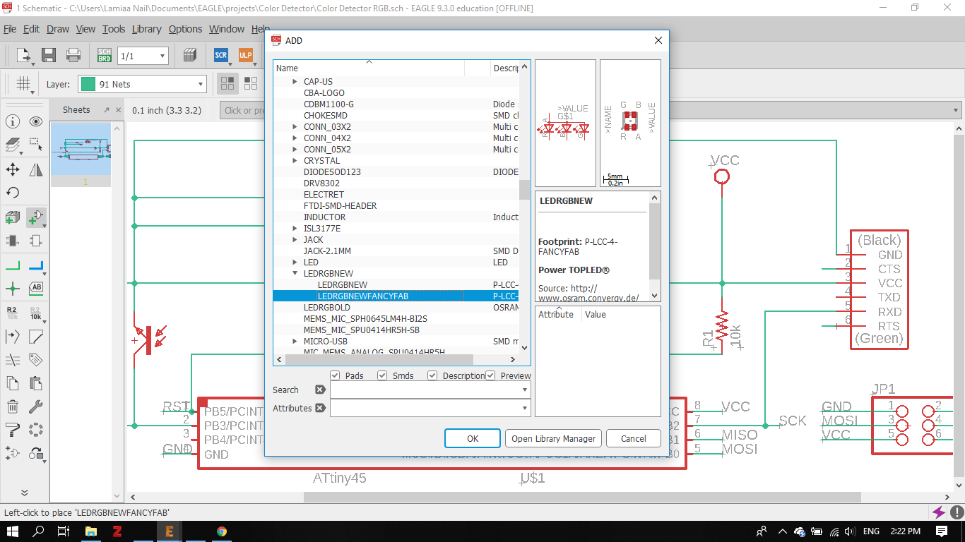
- I designed the board on Eagle by following the RGB LED board design on Fab Academy's website, added the RGB LED component to the phototransistor board from last week.
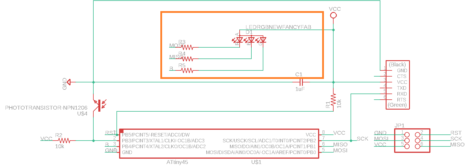
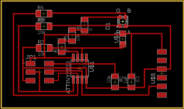
- Here is the final board design from Eagle:
- I milled and soldered the board last week as I mentioned before, and this is the final fabricated board:
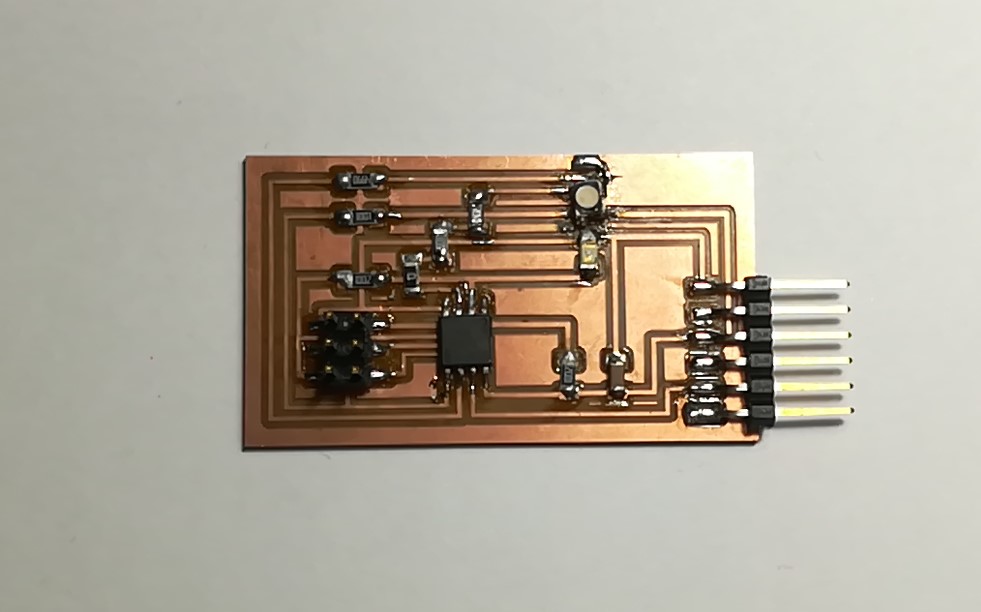
- Now, programming time! I used Arduino IDE to program the RGB LED. I searched around on the internet and found an interesting tutotial on the Arduino project hub to operate the RBG LED.
- I programmed the RBG LED to light up with 8 colors: Red, Green, Blue, Magenta, Cyan, yellow, White and Black. Each color is a combination of 1, 2 or 3 colors as will be shown in the code below.
const byte COLOR_BLACK = 0b000; const byte COLOR_RED = 0b100; const byte COLOR_GREEN = 0b010; const byte COLOR_BLUE = 0b001; const byte COLOR_MAGENTA = 0b101; const byte COLOR_CYAN = 0b011; const byte COLOR_YELLOW = 0b110; const byte COLOR_WHITE = 0b111; const byte PIN_LED_R = 0; const byte PIN_LED_G = A2; const byte PIN_LED_B = 1; void setup() { pinMode(PIN_LED_R, OUTPUT); pinMode(PIN_LED_G, OUTPUT); pinMode(PIN_LED_B, OUTPUT); displayColor(COLOR_BLACK); } void loop() { displayColor(COLOR_RED); delay(100); displayColor(COLOR_GREEN); delay(100); displayColor(COLOR_BLUE); delay(100); displayColor(COLOR_MAGENTA); delay(100); displayColor(COLOR_CYAN); delay(100); displayColor(COLOR_YELLOW); delay(100); displayColor(COLOR_WHITE); delay(100); displayColor(COLOR_BLACK); delay(100); } void displayColor(byte color) { digitalWrite(PIN_LED_R, !bitRead(color, 2)); digitalWrite(PIN_LED_G, !bitRead(color, 1)); digitalWrite(PIN_LED_B, !bitRead(color, 0)); }
- For the first part of the code, we need to define each of the 8 colors. Each color's value is stored in a byte that contains a unique value. The last 3 bits are simply the on/off signals of the 3 LEDs. For example, the black color means to turn off all LED, so the 3 bits are assigned 000, Whereas, for the white all the 3 LEDs should be lit, so the 3 bits are assigned the value 111.
- Using the pinout diagram of ATTiny 45, I mapped the 3 pins PB0, PB1 and PB4 in the ATTiny 45 to 0, A2 and 1 respectively in the Arduino.
- Using the pinout diagram of ATTiny 45, I mapped the 3 pins PB0, PB1 and PB4 in the ATTiny 45 to 0, A2 and 1 respectively in the Arduino. I set the pinMode of these 3 pins to Output.

- For the next part of the code, a function was created (displayColor) that takes the color as a parameter and outputs the associated byte.
- The function bitRead() takes a number and read a bit of it. So, it takes the number 001 which correspondes to the color blue, it will read the first bit and assign its value (0) to the red LED, so it will be turned off, assign the second bit's value (0) to the green, so it will be turned off as well, and finally assigns the third bit's value (1) to the blue LED, turning it ON. Thus it will display the blue color
- I finally uploaded the code to the board:
- The first time I uploaded the code, the LED displayed 3 colors only, and I found out the problem was that I didn't solder the RED pin well. Once I did soldering, the RGB LED displayed the full range of colors as shown.
Output Device #2: Servo Motor
- For my final project, I will be using servo motors to animate the animatronic face features, so I chose to work with servo motor for this week's assignment.
What is PWM (Pulse width modulation)?
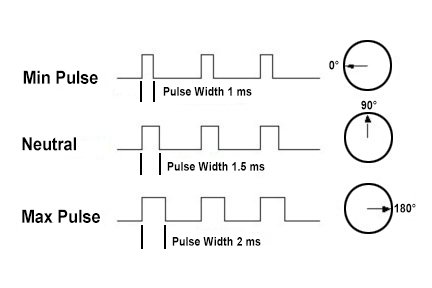
Servo motors are controlled by sending out pulses of variable widths or pulse width modulation (PWM) through the control wire. The pulse that a servo take determine the position of its shaft. The minimum pulse (1 ms) rotates the shaft to the 0 degrees position, the neutral pulse (1.5 ms) rotates to the 90 degrees position, and the maximum pulse rotates to the 180 degrees position. The servo motor expects to receive a new pulse every 20 ms.
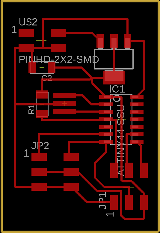
- I redesigned the servo motor board from the Fab Academy website, using the ZLDO1117 voltage regulator.
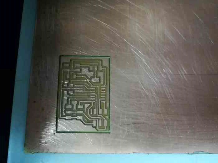
- Then, I imported the board design into Fab Modules to prepare it for fabrication on the Modela.
- Finally, I soldered the board and now it is ready for programming!
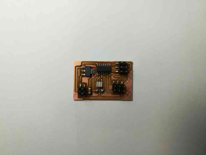
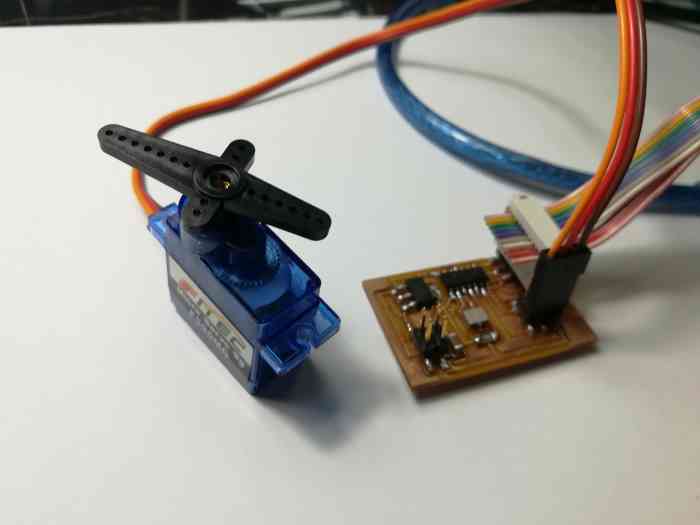
- To control the servo motor, I needed first to configure the Attiny 44 to use the external crystal, so I used the make fuse command.
- Then, with the help of our instructor, our first attemp was using Arduino IDE to program the board. Arduino IDE provides a whole servo library. I used the sweep example on the Arduino IDE, I just changed the output to pin 7 where the servo is attached to the Attiny 44. However, it didn't work.
- We figured that the servo library will not be suitable for the Attiny 44. Thus, our second attempt was to write a PWM script on Arduino IDE. The idea of the script is very similar to Neil's C code.
- For the first position (0 degrees), we send a high signal that lasts for 1 ms, then a low signal that lasts for 20 ms - 1 ms = 19 ms.
- For the second position (90 degrees), we send a high signal that lasts for 1.5 ms, then a low signal that lasts for 20 ms - 1.5 ms = 18.5 ms.
- For the third position (180 degrees), we send a high signal that lasts for 2 ms, then a low signal that lasts for 20 ms - 2 ms = 18 ms.
- This attempt failed as well. Our hypothsis is that the digitalWrite() function might not be working well with the Attiny 44 as well. The problem might be a timing problem.
- Our third attempt was actually trying out Neil's code for software PWM. I made minor edits to the code, I kept only the code parts to control one servo motor.
- I used the make program command to upload the c code to the board using FabISB: make -f hello.servo.44.2.make program-usbtiny
- The outcome:
- I noticed that the rotation angles were not 0 90 180 degrees as expected, it is 0 45 90 degrees instead. After consulting our instructor, we learned that these angles changes from one servo motor to others, and we should get back to the datasheet to check the corresponding angles before programming the board.
Group Assignment: Power Consumption
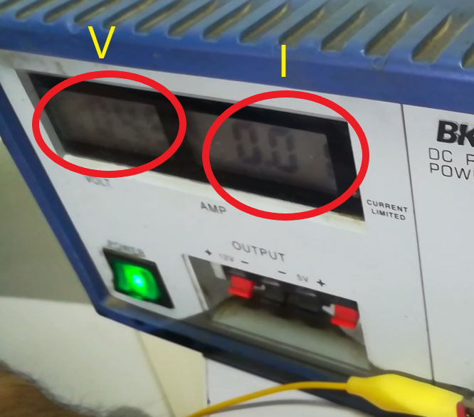
- We adjusted the input voltage to 5 V.
- We connected 2 aligator wires to the power supply leads, one to the positive lead and the other to the ground lead of the power supply.
- Then, we tested the RGB LED's by supplying it with voltage, by putting the positive and negative leads around it.
- Now, we notice the amount of current the LED draws from the power supply. For the RGB LED it is around 0.01 amps.
- To calculate the power consumption we use the equation: P= I X V= 0.02 X 4.9 = 0.049 Watts.
Design Files