Computer-controlled Machining Week #8
Introduction
This week we have two main assignments:
- Individual Assignment: Make (design+mill+assemble) something big
- Group Assignment: test runout, alignment, speeds, feeds, and toolpaths for your machine
Design something big
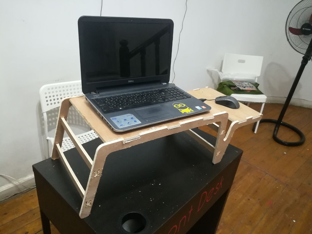
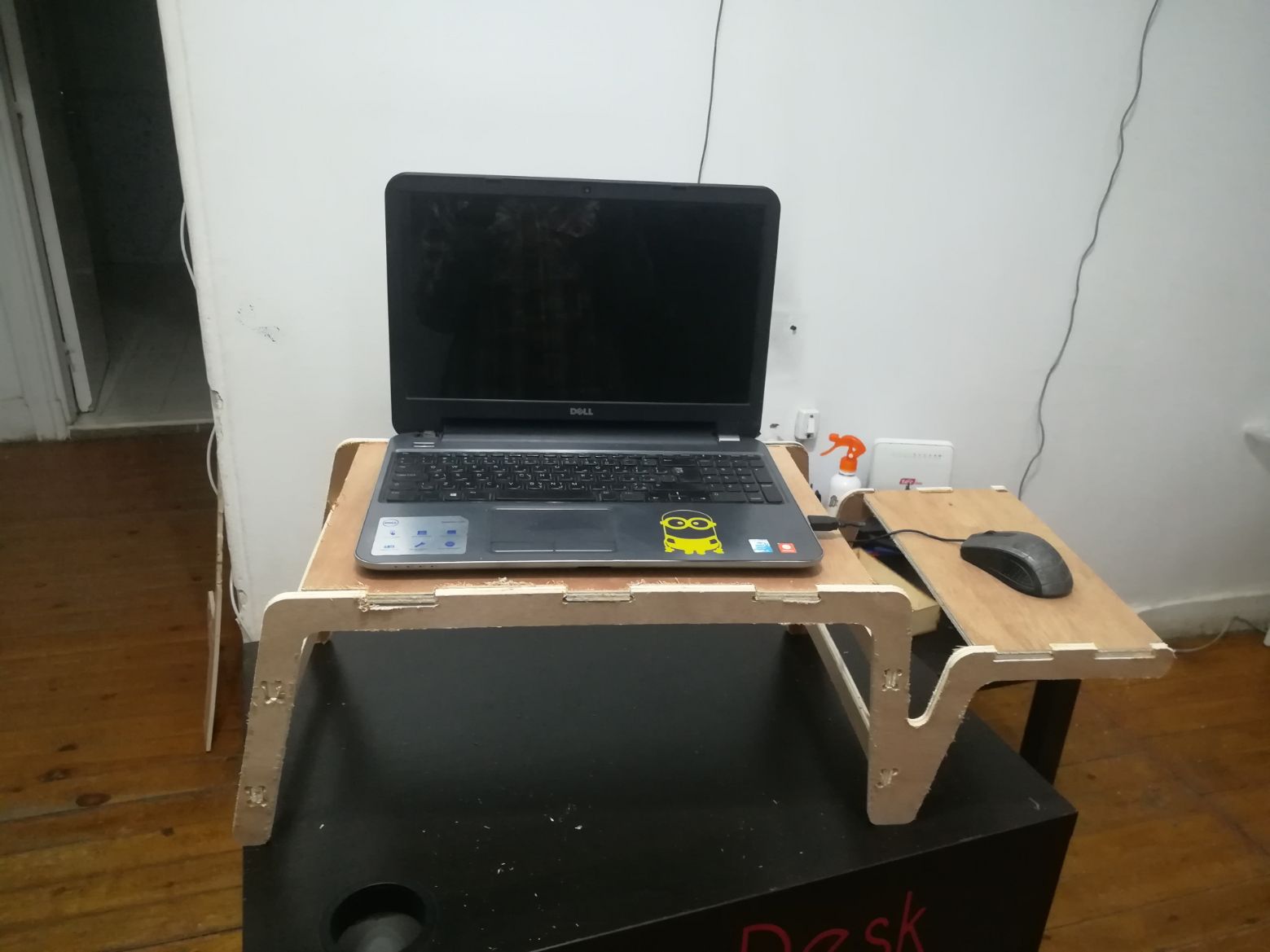
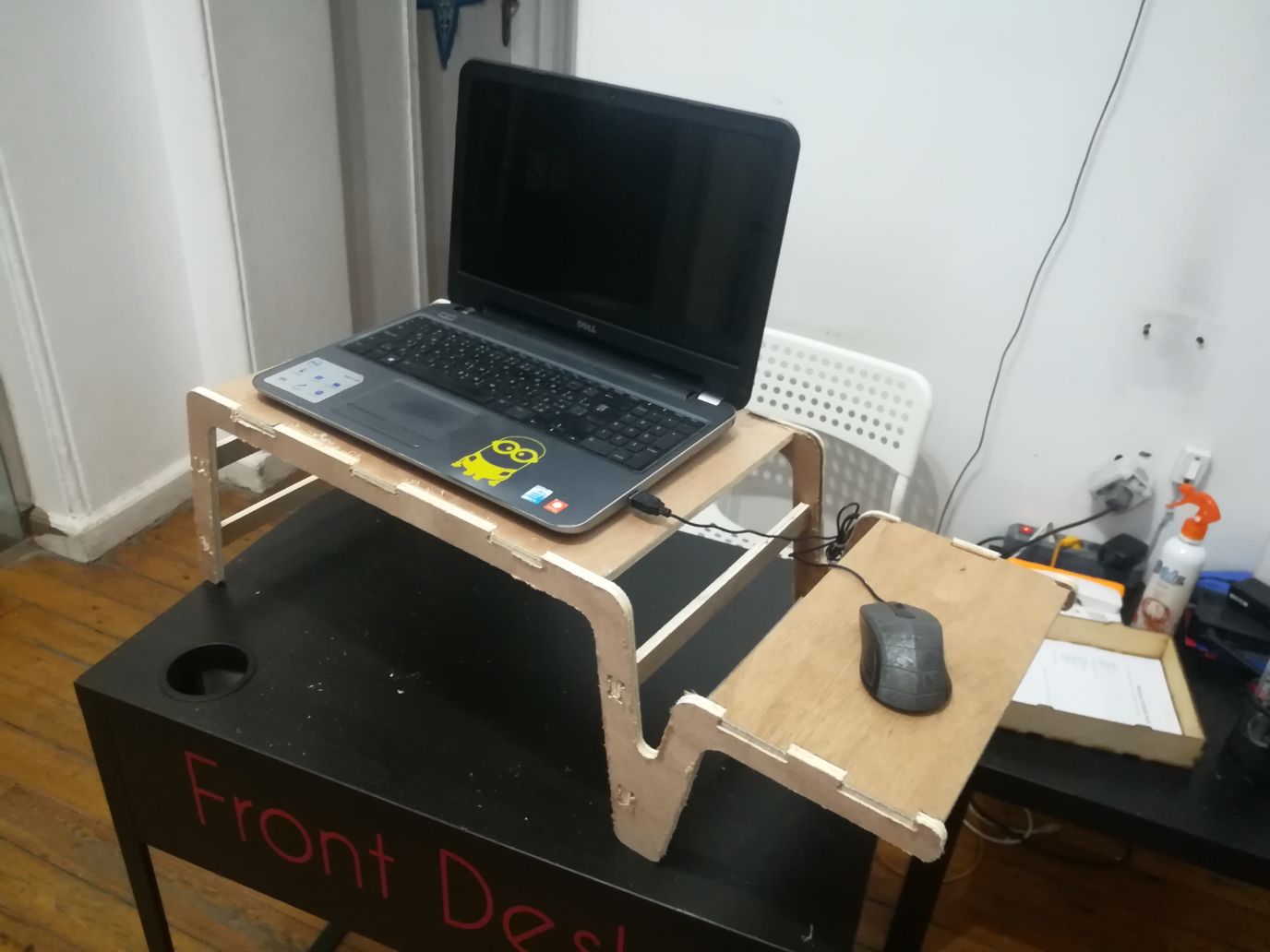
- For this assignment, I decided to build a laptop stand that I can use while laying down in bed.
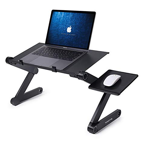
- I used Fusion 360 to design the laptop stand. The laptop stand consists of 4 parts: tabletop, Mousepad, legs and supports.
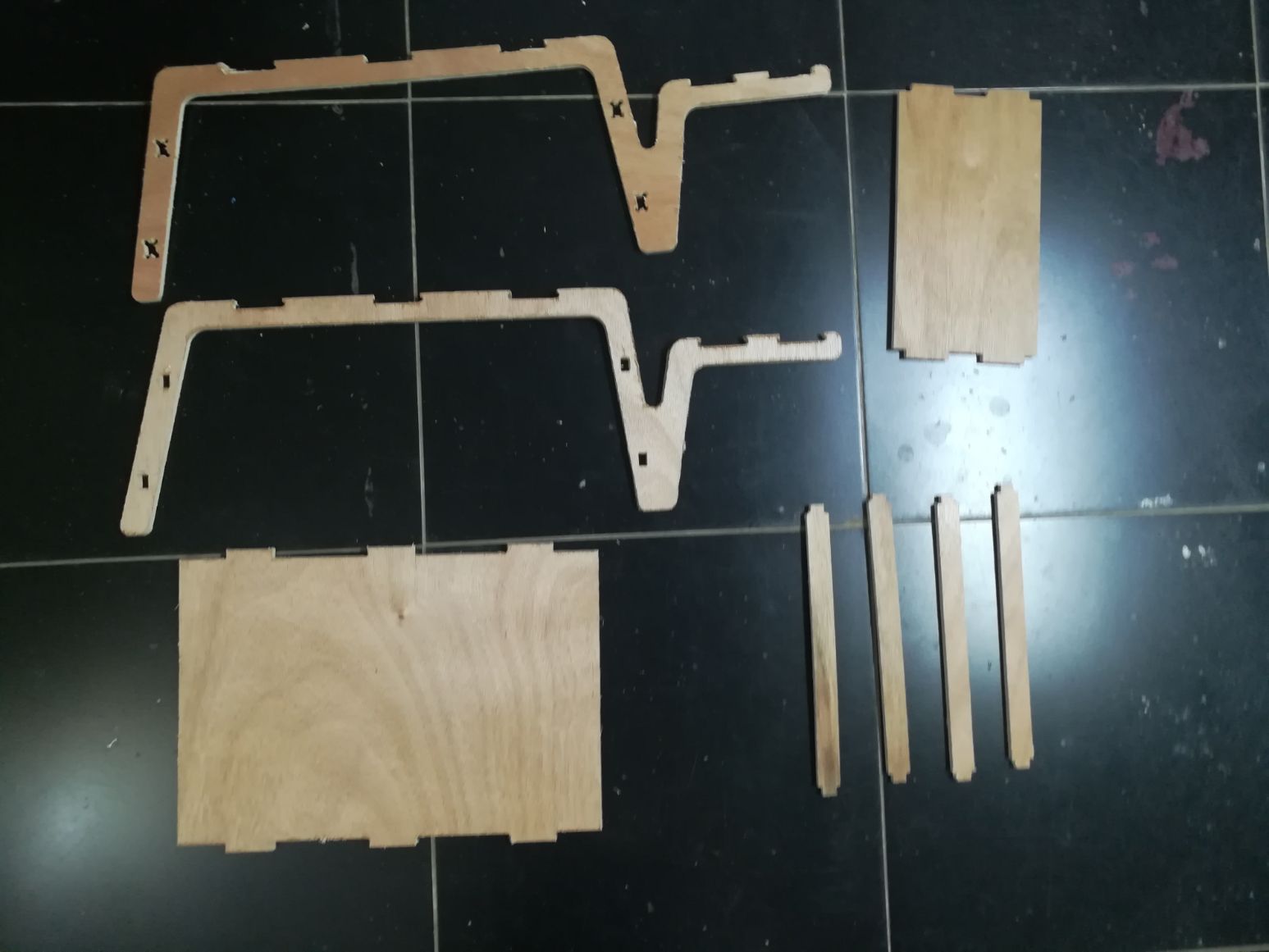
- Leg part: two pieces of this part will be fabricated (front and back legs)
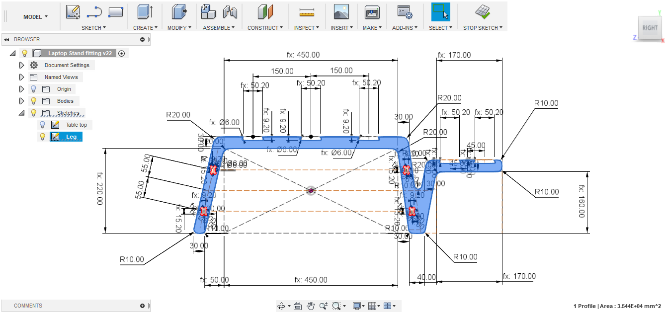
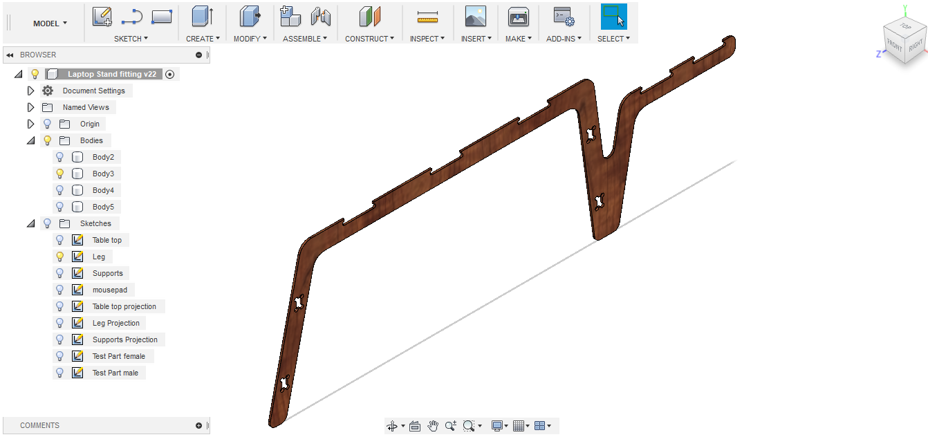
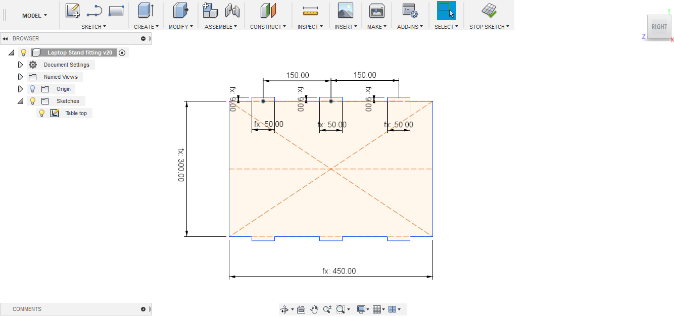
- Table-top part: one piece of this part will be fabricated
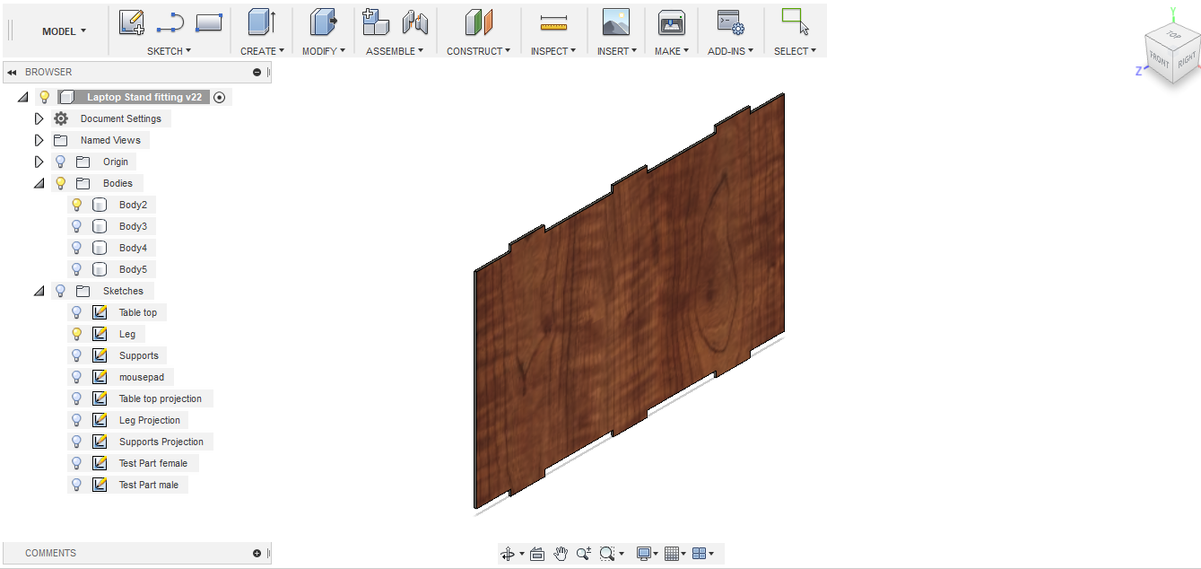
- Mousepad part: one piece of this part will be fabricated
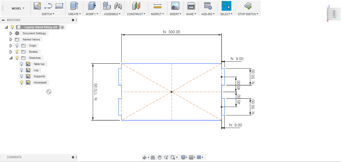
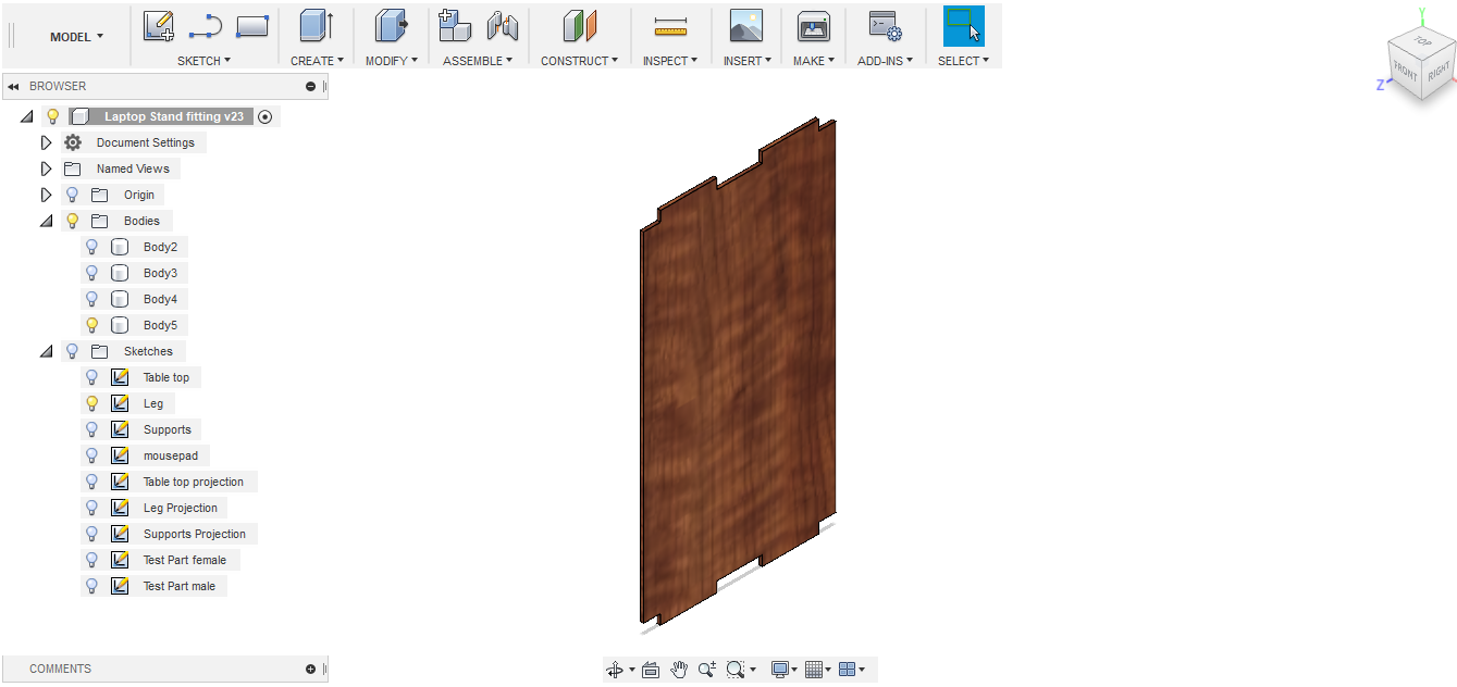
- Supports part: four pieces of this part will be fabricated
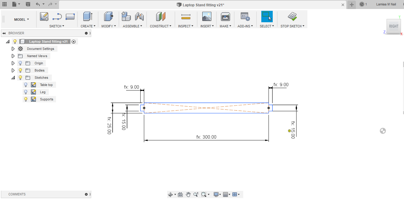
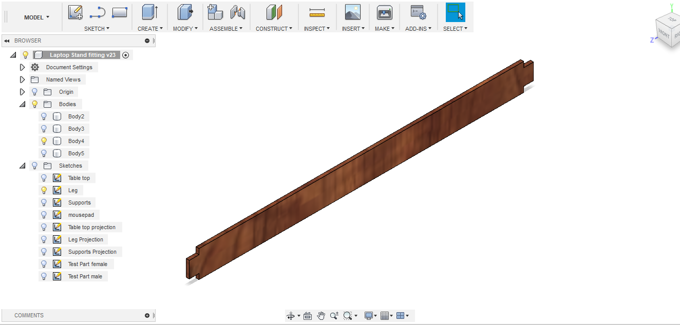
- I designed the laptop stand parts to press-fit together, for this purpose I created dog-bones in the female part (the front and back legs), where the supports will press-fit, and T-bones where the tabletop and mousepad press-fit
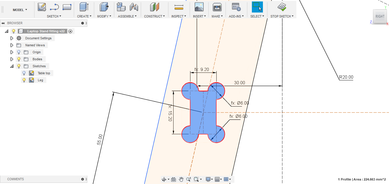
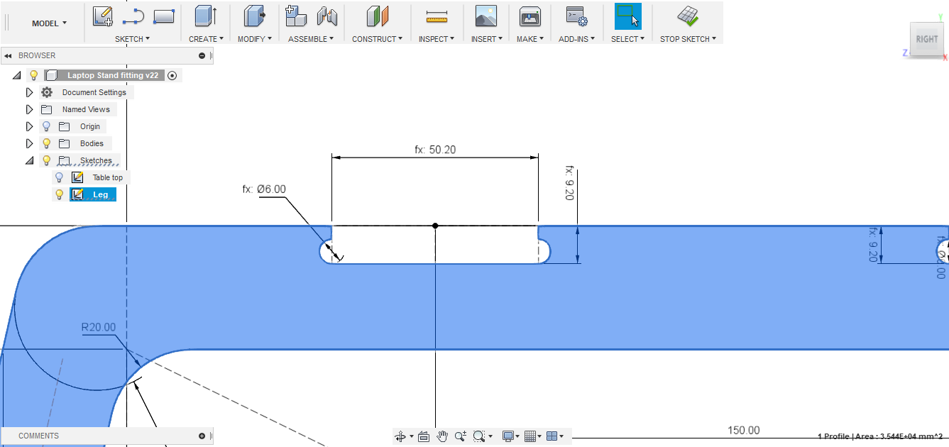
- For the parts to actually press-fit together nicely, I needed to test for the tool tolerance. For this purpose, I designed two small test parts, one male and one female. I first created a parameter named "tolerance", so that I can change it easily during tests. The final tolerance that made the parts pressfit nicely was 0.2 mm.
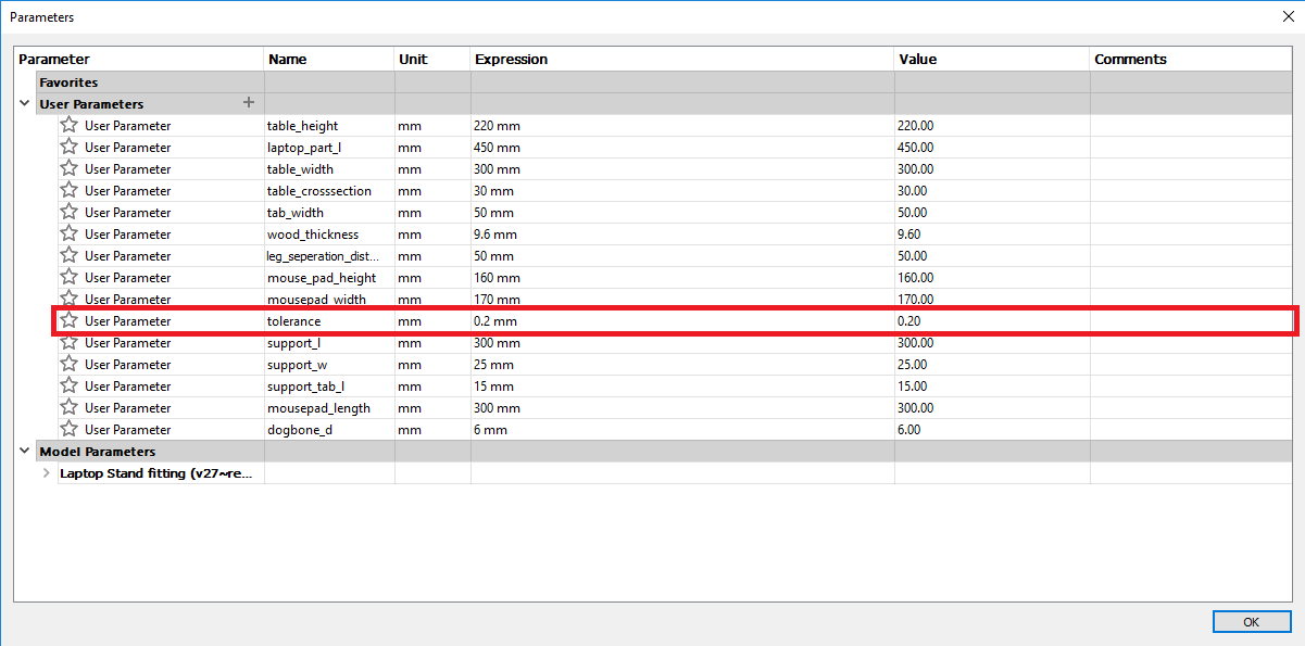
- I put the tolerance parameter into consideration while designing female dog and T-bones, while I kept the male part dimensions the same.
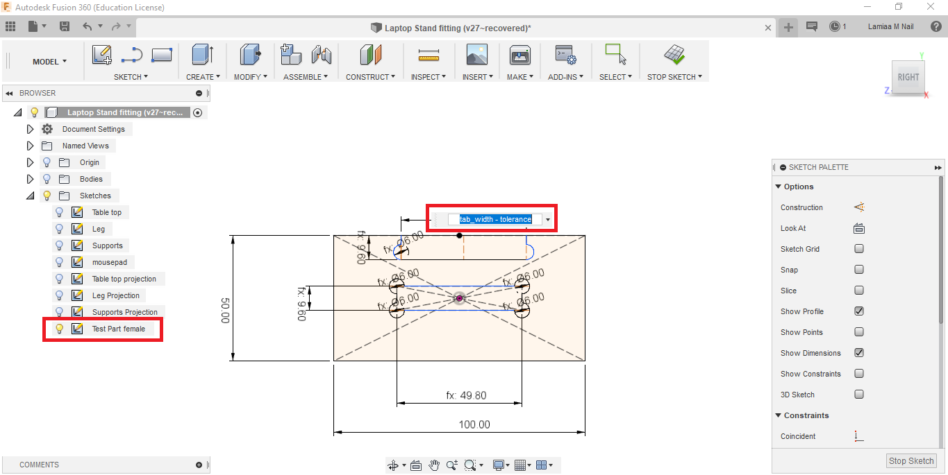
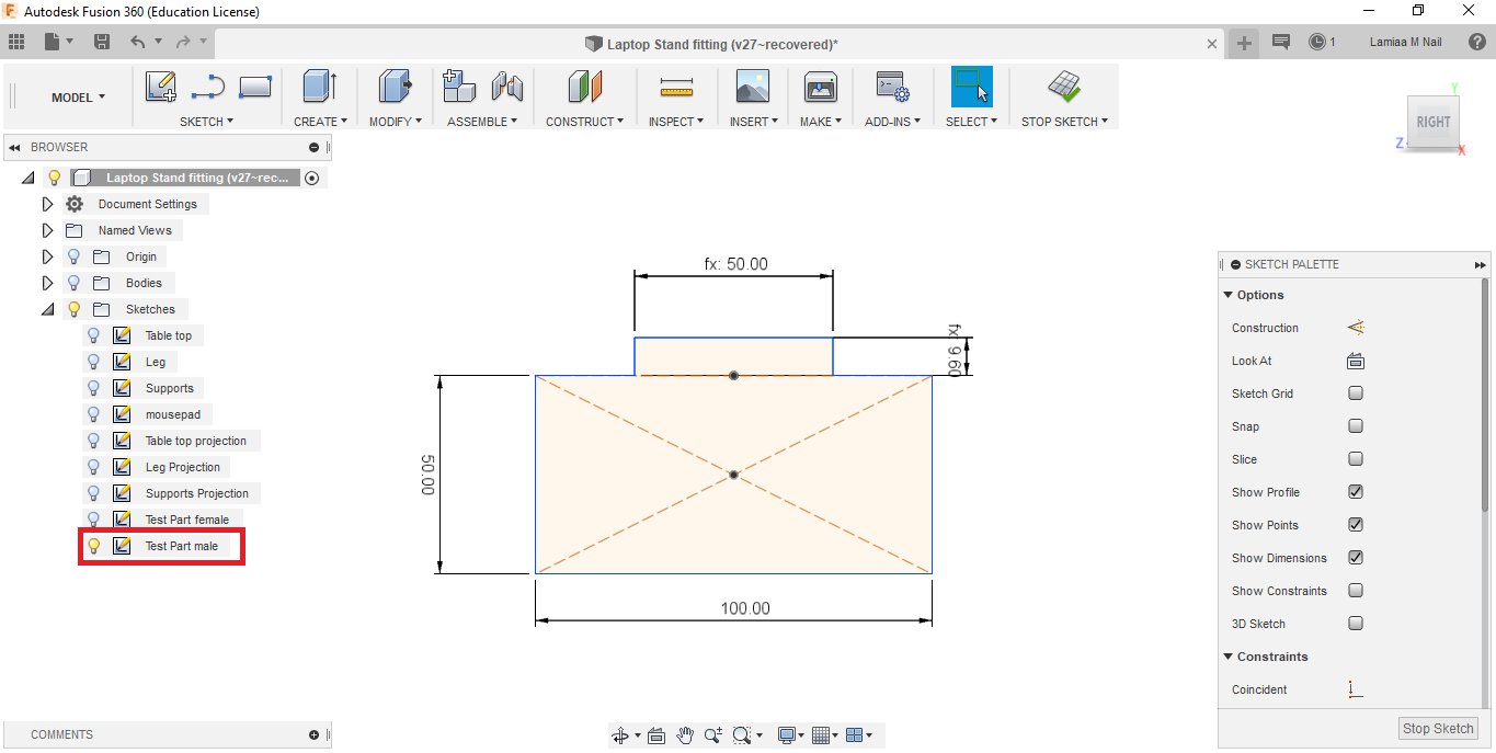
- After finsihing the design, I exported the 4 parts in DXF format to prepare for fabrication.
Mill something big
- I used Autodesk ArtCam software to create the toolpath for the CNC machine.
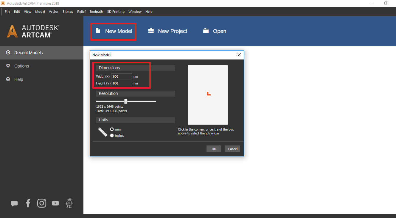
- First, I created a new model and started with setting the dimensions of the plywood sheet (600 mm x 900 mm)
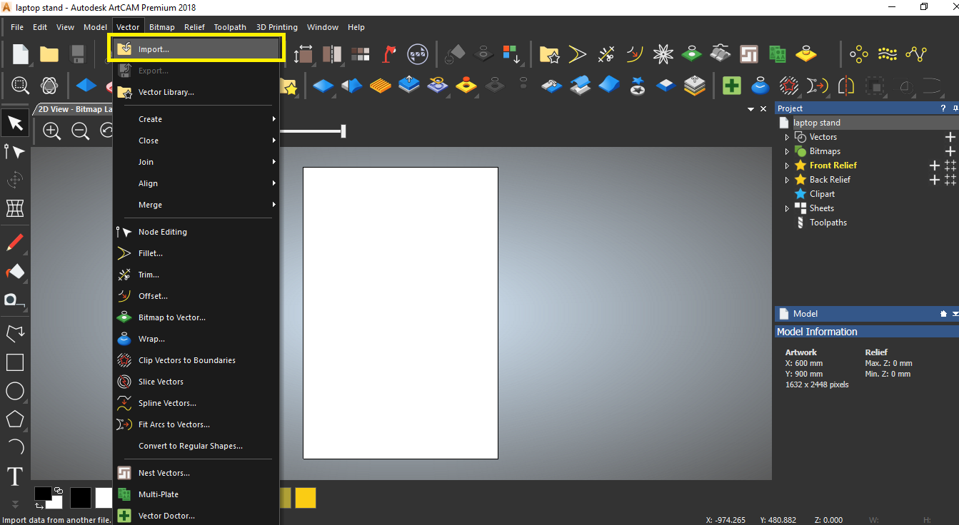
- Afterwards, I imported the DXF files of my design into Artcam, and aligned the parts on the sheet
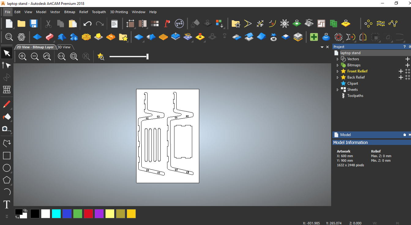
- Then, I started with setting up the material.
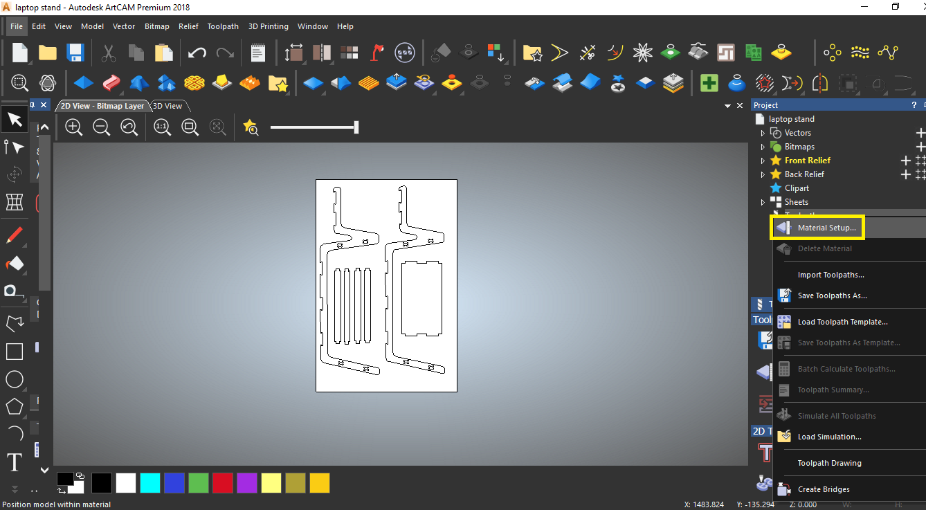
- Setting the material thickness is not that trivial! The "commercial" thickness of the plywood sheet that we used is 9 mm. However, the actual thickness varied from 9.1 to 9.6 mm in different parts of the sheet!
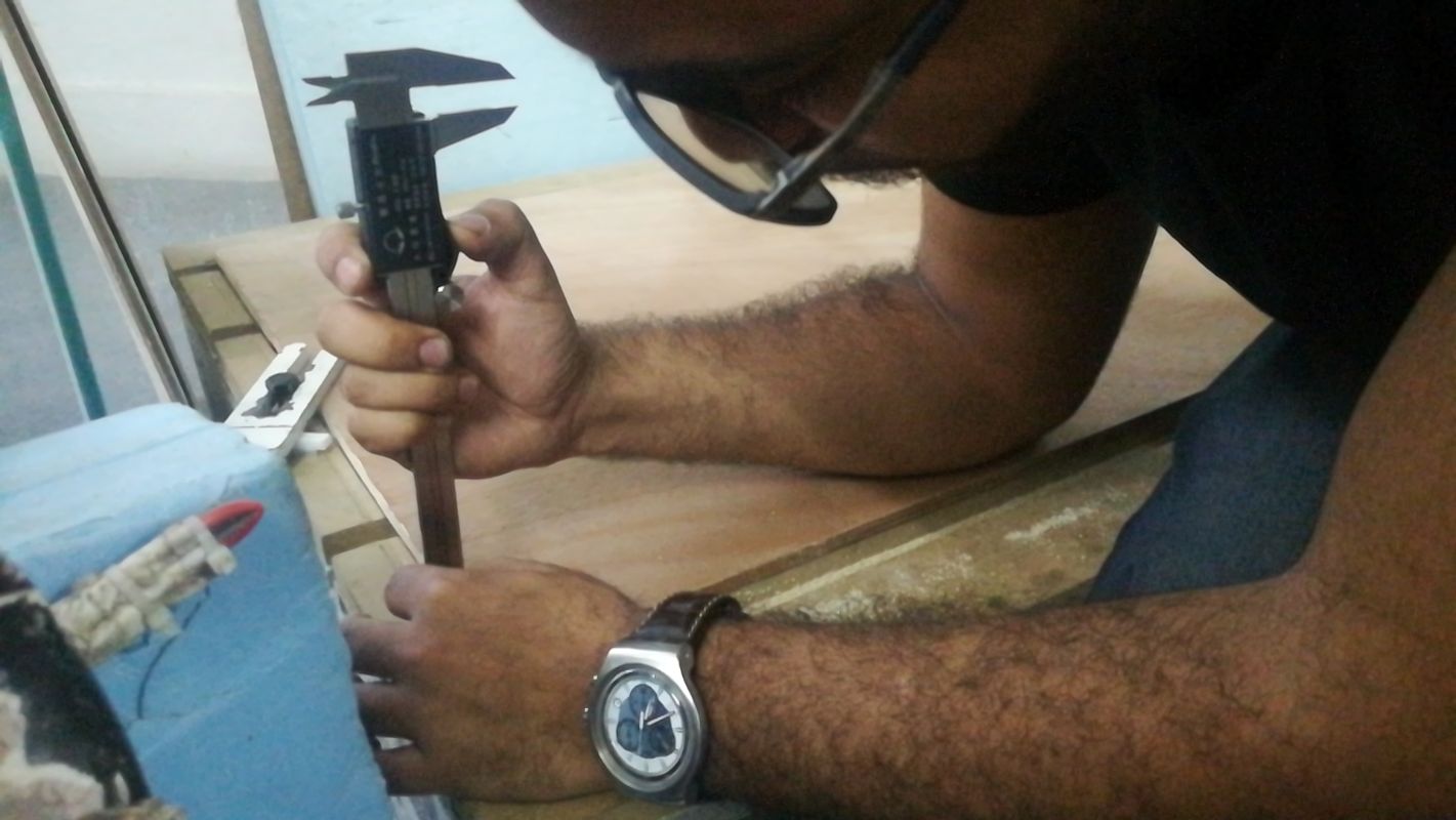
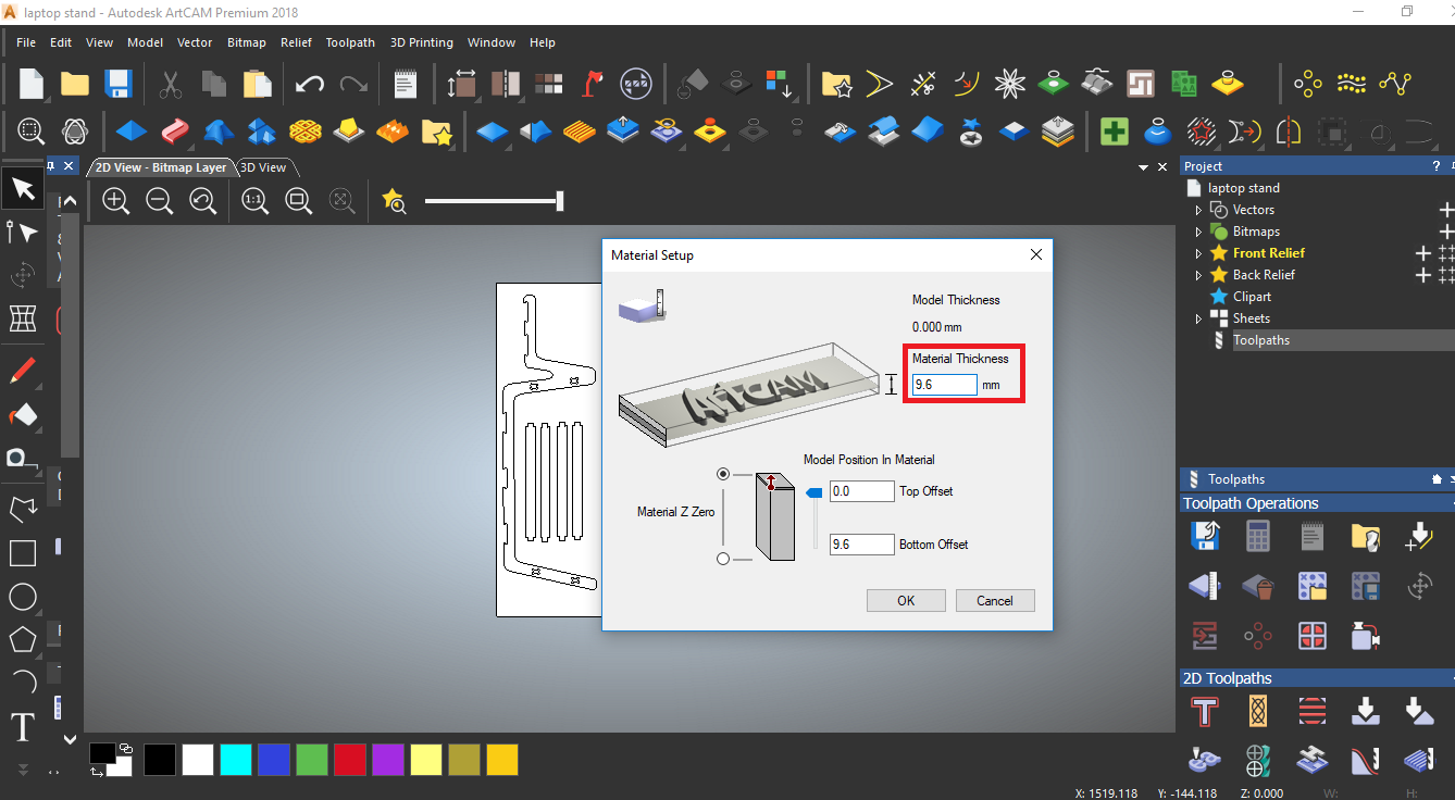
- So to be safe, I set the wood thickness to the maximum measured thickness 9.6 mm.
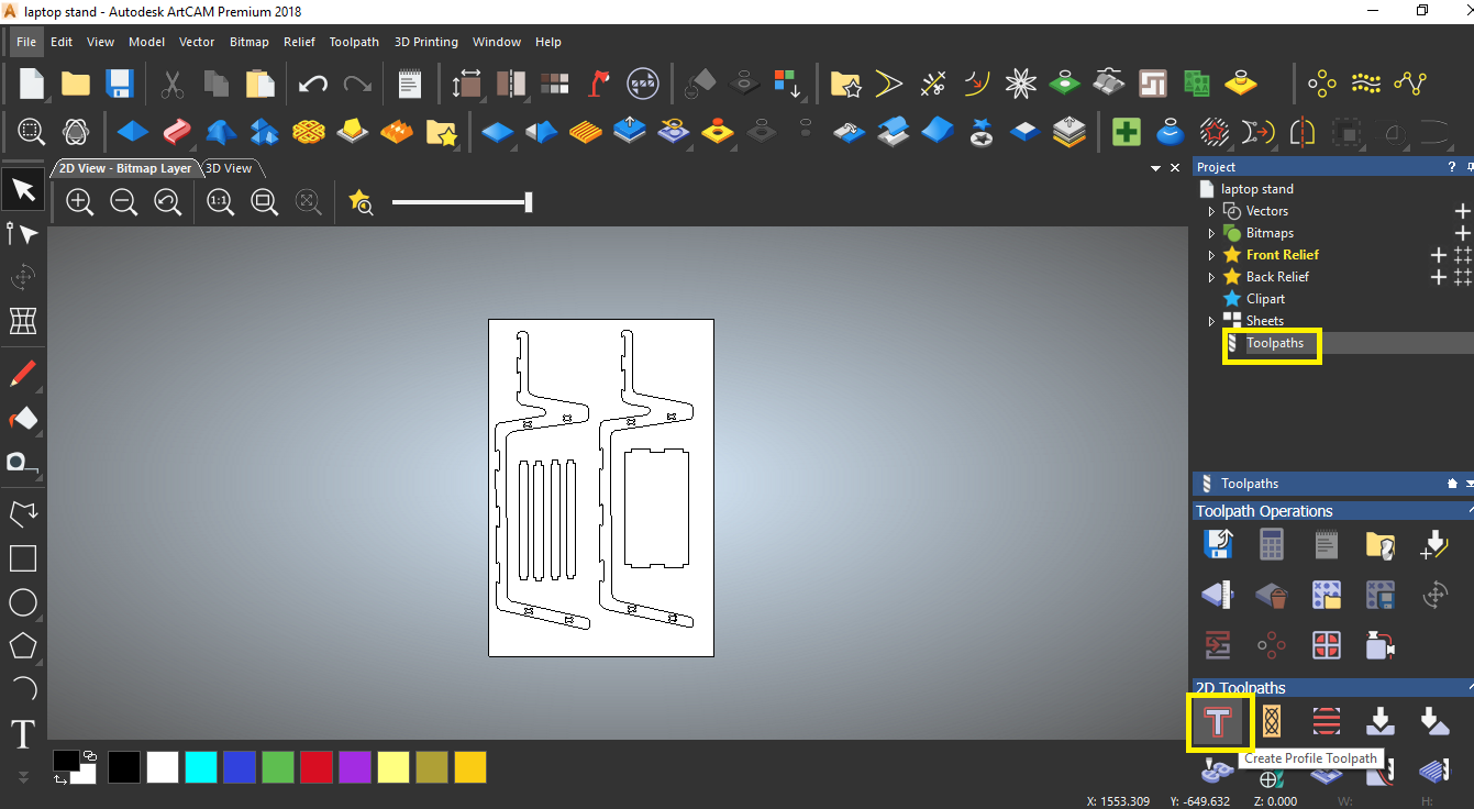
- Now, it is time to create the toolpath. Press 2D toolpath icon, the Profiling window will open.
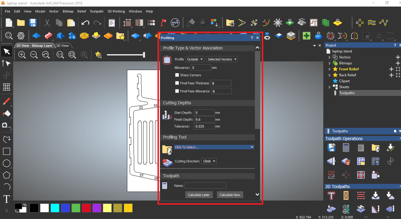
- Set the finish depth again to the maximum measured wood thickness 9.6 mm.
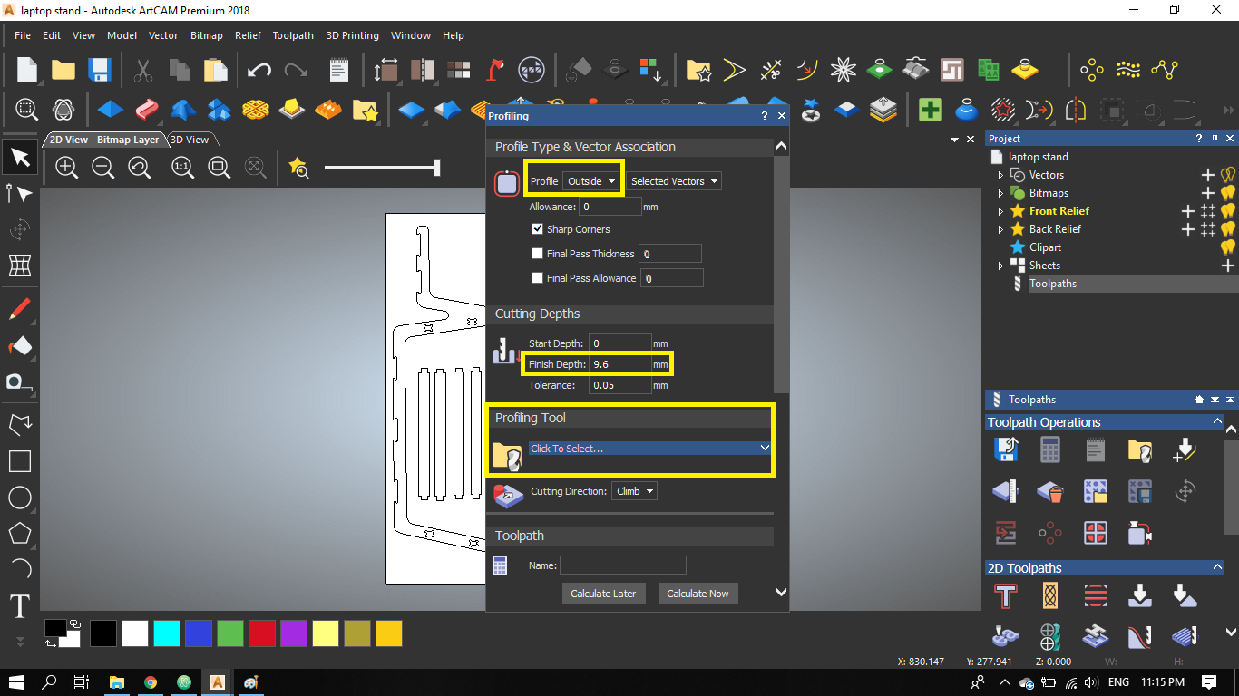
- The most important step of the process, setting the tool to a 4 mm endmill. I set the default machining values including the spindle speed, feedrate, and plunge rate.
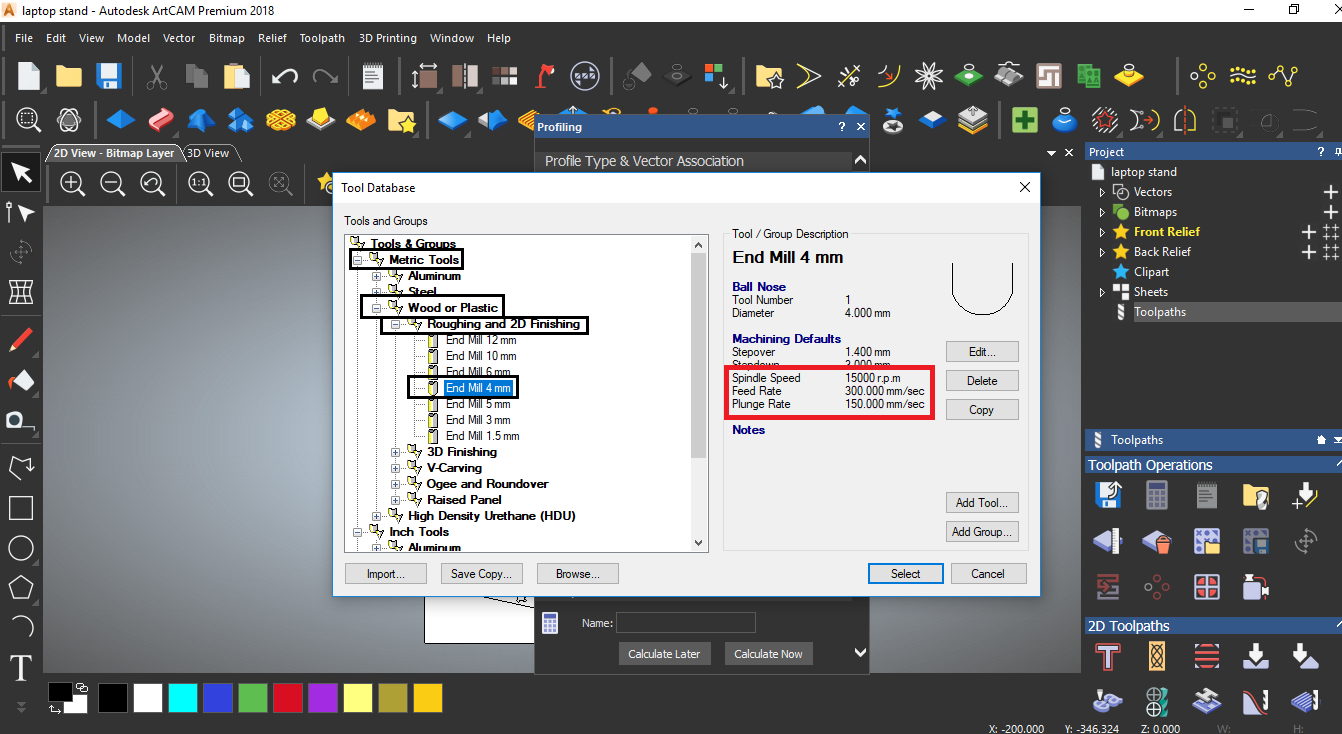
- The stepdown is set to 3 mm, which means that the endmill will go down 4 times to finish the cut along the wood thickness
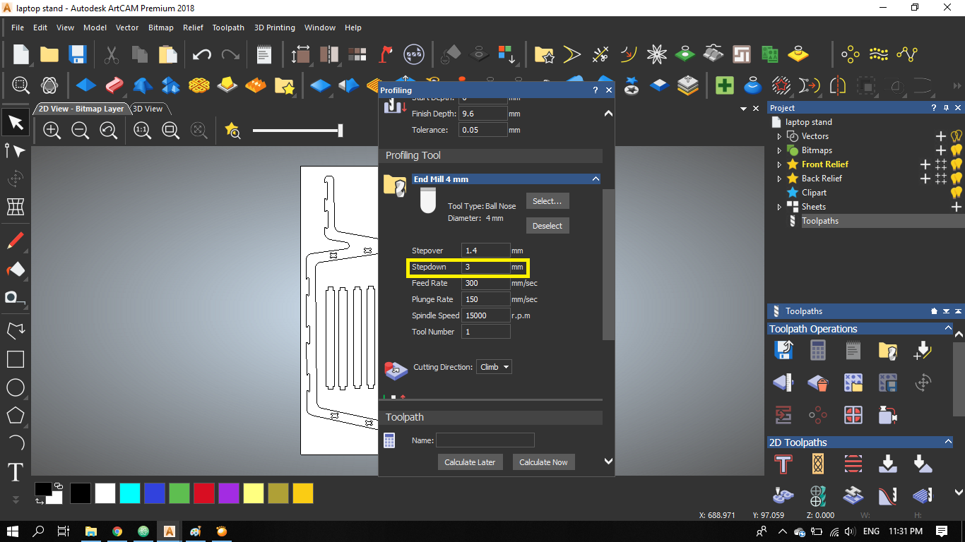
- Finally, I calculate the toolpath.
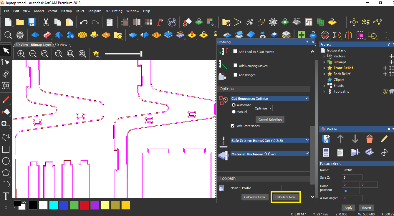
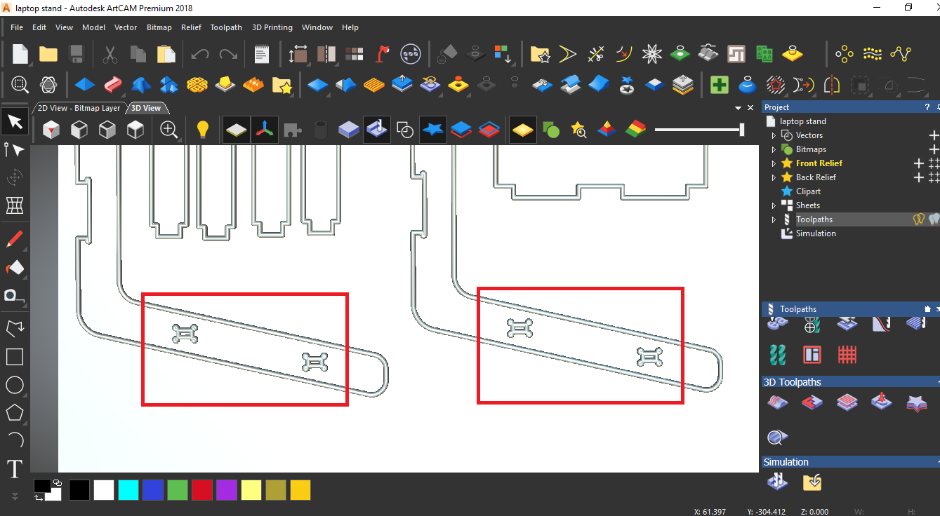
- It's important to simulate the toolpath afterwards to make sure that all the lines and specially the press-fit female parts are detected in the toolpath.
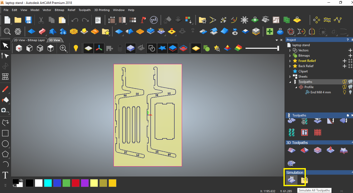
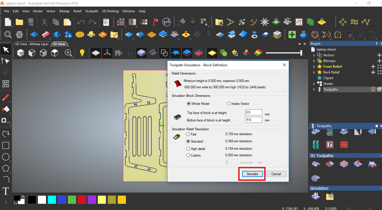
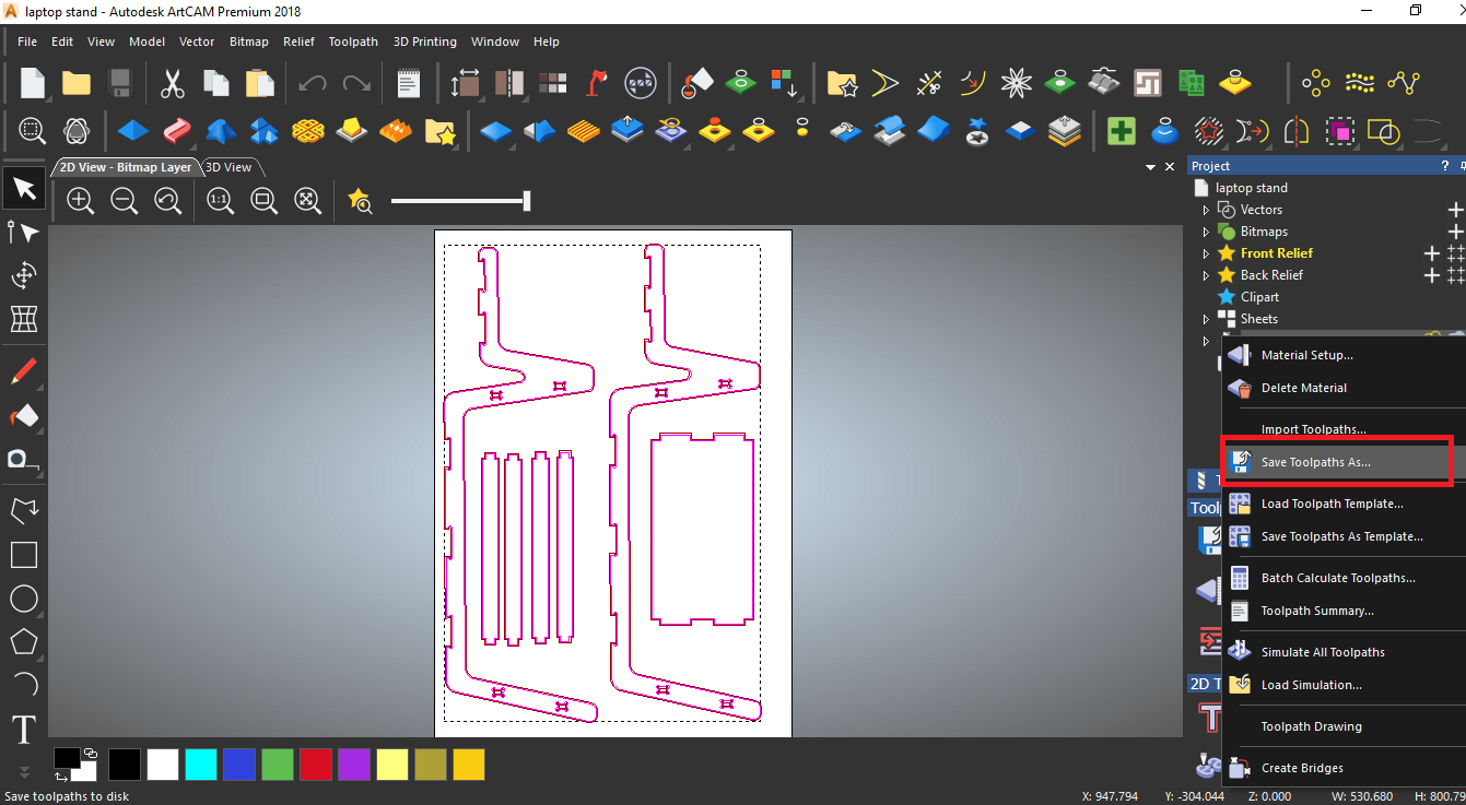
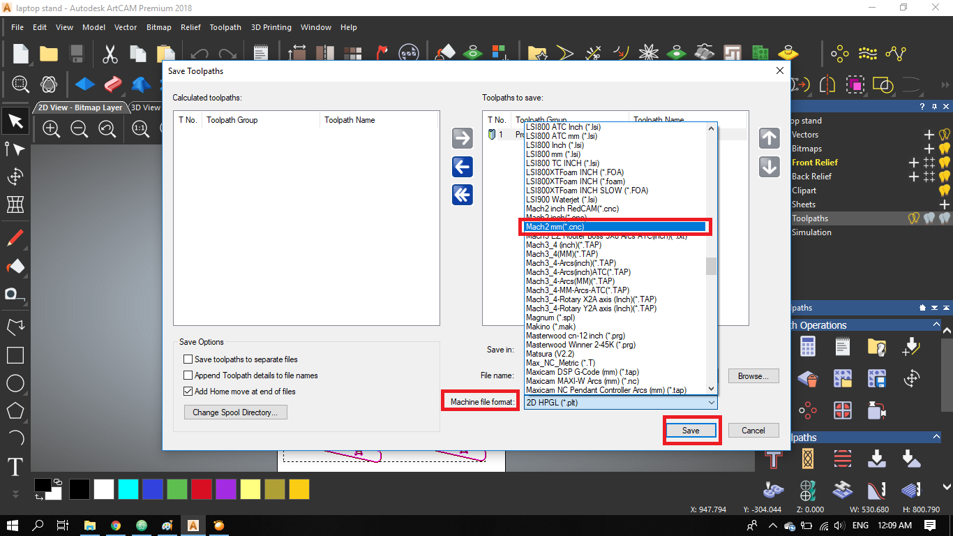
- Finally, I save the toolpath's gcode, and choose the format that is compatible with our CNC machine.
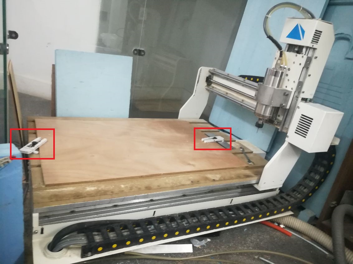
- Now, it's time to prepare for cutting, fixed the plywood on the CNC bed.
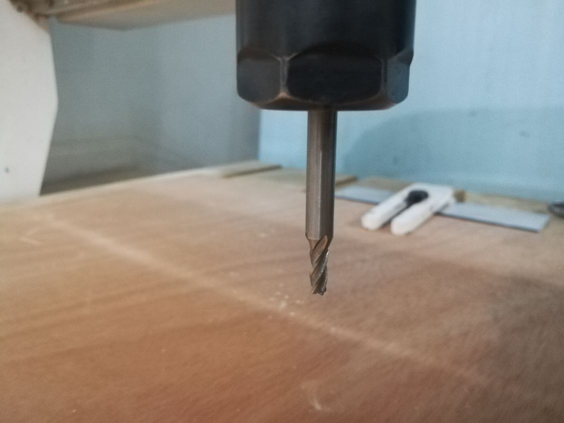
- And, fixed the 4 mm endmill to the spindle
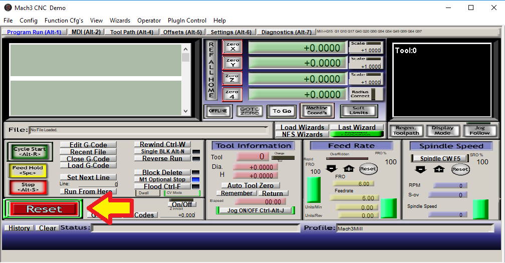
- Now, I used Mach3 Sotfware to control the CNC machine. Starting with powering up the machine and pressing the "reset" button to get into safety mode.
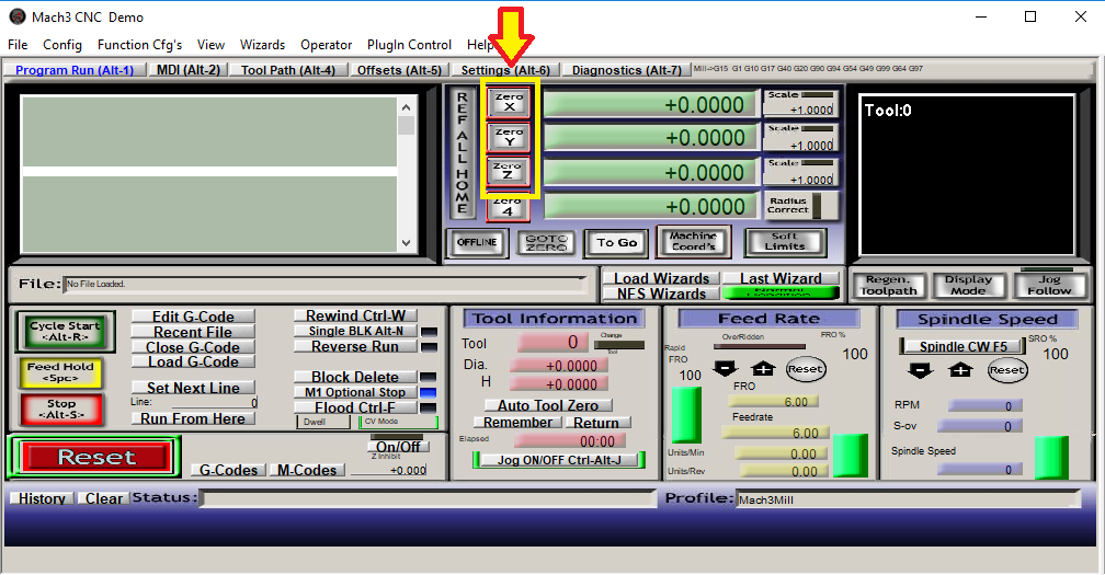
- To set the zero point, I started to move the endmill until I reached the desired zero point then I set it on the software by pressing the zero X, zero Y and zero Z buttons.
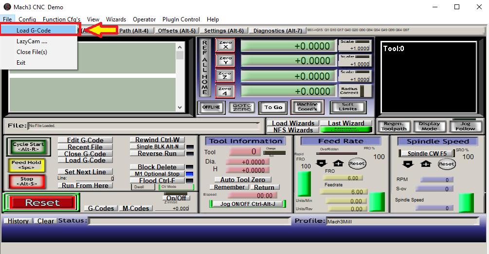
- Now, I import the gcode that I exported earlier, and I can see the associated toolpath on the screen's corner.
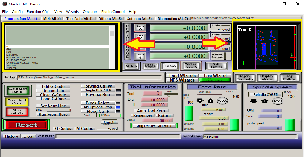
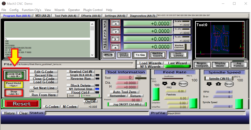
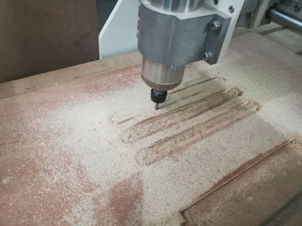
- Finally, I press "Cycle start" to start the excuting the code.
Assemble something big
- Now the parts are ready for assembly!
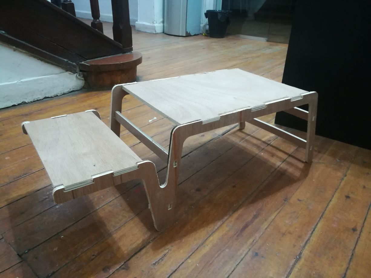
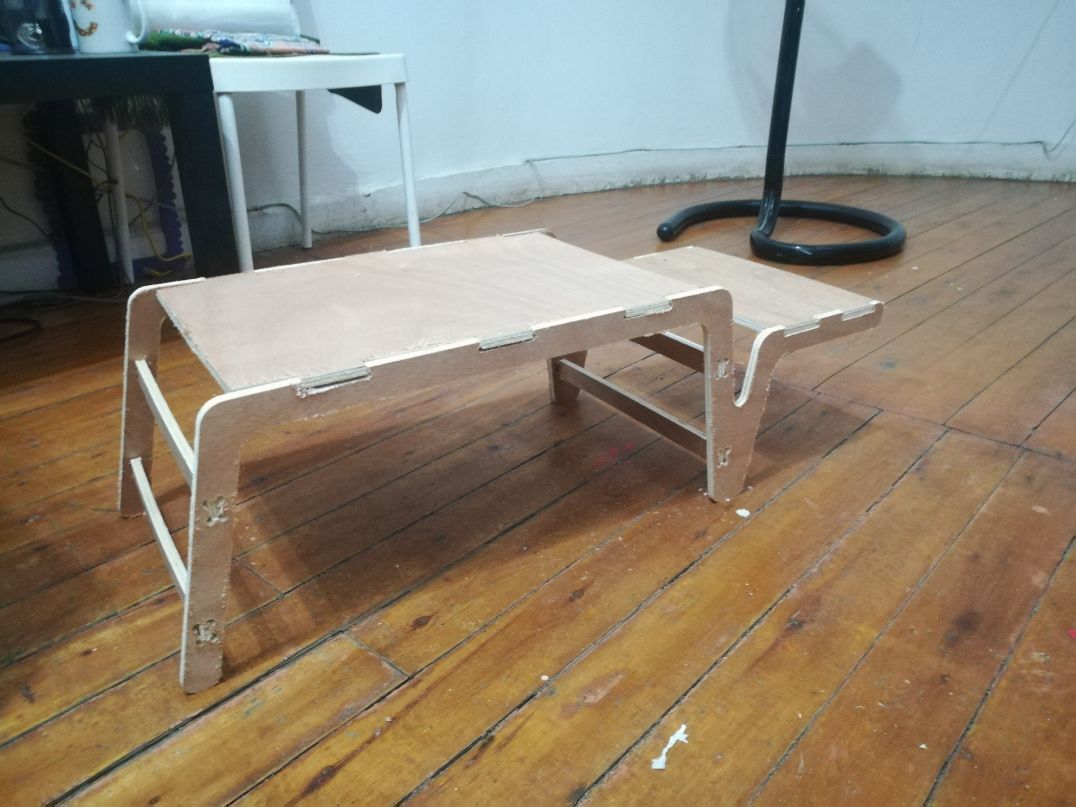
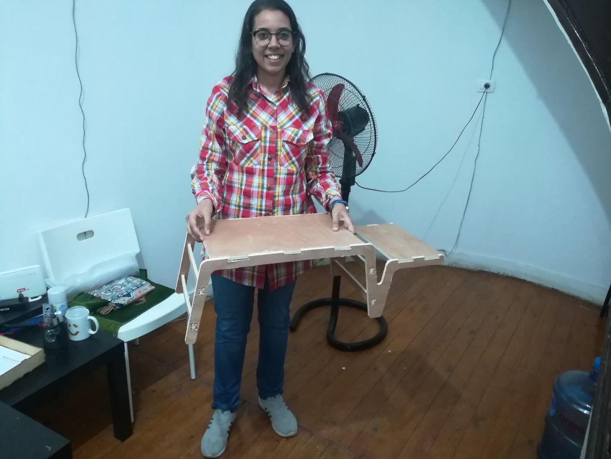
- Working from bed will be more fun!
Design Files