3D Scanning and Printing Week #6
Introduction
This week we have three main assignments:
- Design and 3D print an object (small, few cm3, limited by printer time) that could not be made subtractively
- 3D scan an object (and optionally print it)
- Test the design rules for your printer(s)
1. Design and 3D print an object (Individual Assignment)
1.1 Designing the object
- I used Autodesk Fusion 360 to design my object.
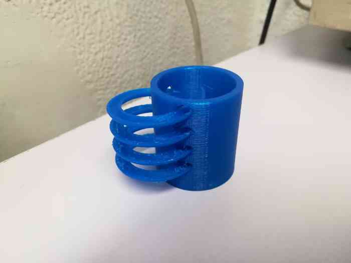
- My object of choice is a marble track, the track is helix, embedded within a cylinder which act as a scaffold for the track.
- I followed this tutorial to learn how to design the helix.
- I started with creating a cylinderical shape, using the pipe tool.
- Then, I created a coil, which aligns exactly with the cylinder.
- Then, I projected a helix from the coil.
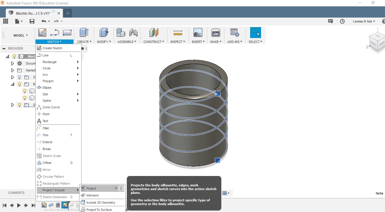
- Then, I created a new plane at the lowest point of the coil, where I sketched a half ring shape.
- Then, I used the sweep tool to create the track. I chose the helix as the path, the half ring as the profile, and the cylinder that I've created earlier as the guiding surface.
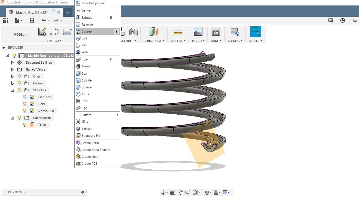
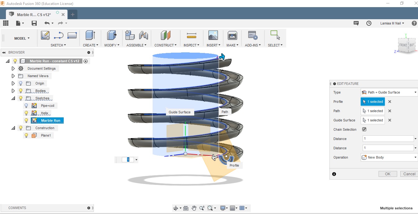
- I finally created the scaffold cylinder, within which the track is partially embedded.
- This object cannot be fabricated subtractively considering that the helical curvature of the track cannot be shaped and accessed by a milling tool.
1.2 printing the object
- I used the Ultimaker software to set the printing parameters and slice the object. I used a 20% infill and 0.2 mm layer height. And I used supports between the rings of the track.
- I used the Prusa i3 MK3 to print the marble track.
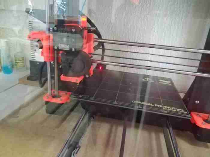
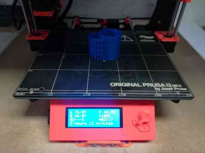
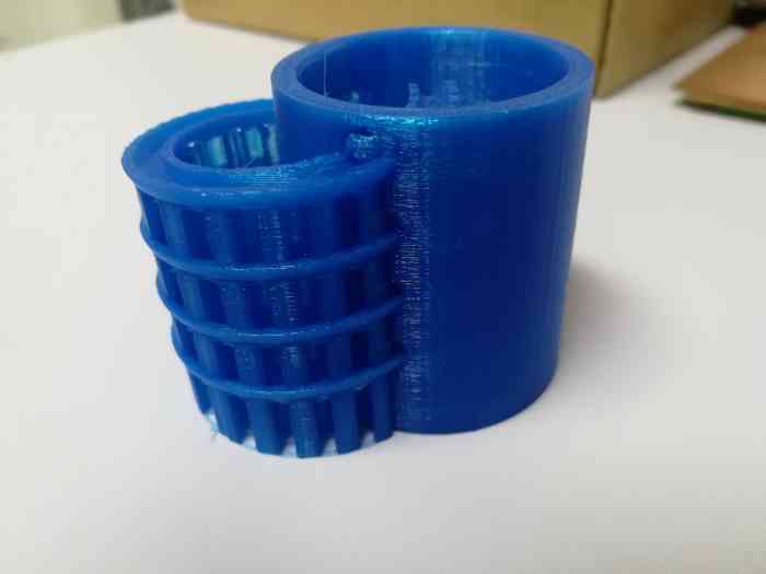
- I finally removed the supports between the tracks, but it was really hard to remove, and the supports inside the cylinderical scaffold were hardly accessible.
2. 3D Scanning an object
- MY software/app of choice for 3D scanning, is Qlone, mobile application that can be used for scanning, constructing and editing a 3D object.
- The app is available on Google play, I downloaded and installed the app on my phone.

- Before using the app, I watched a quick tutorial/commerical on how to use it
- From the video, I was facinated by the app, not putting in mind how commercials usually cover up the defects as I discovered later after using the app.
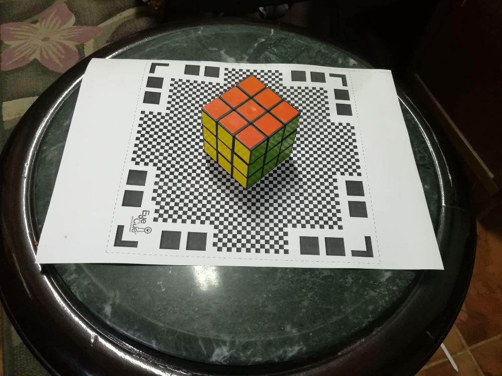
- The app requires download a "mate" a pixel-like black and white image to print and put underneath the object.
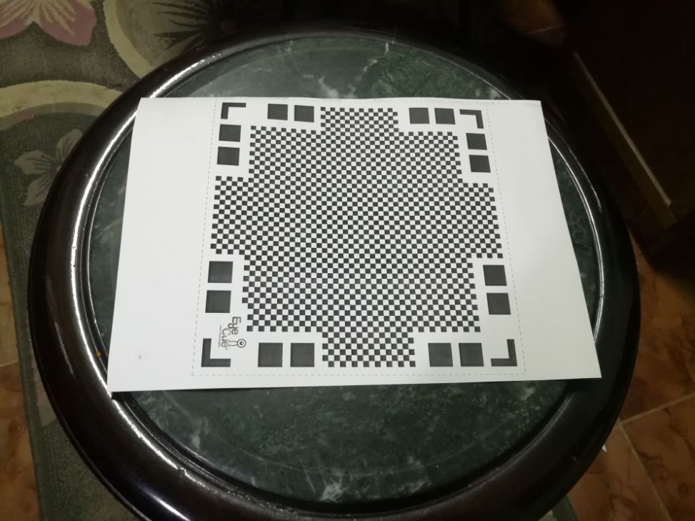
- My object of choice is a Rubik's cube. I placed it exactly at the center of the mate as instructed in the video.
- I opened the app, and clicked the "+" sign in the lower right corner to start a new scan.


- An agumented reality (AR) domw appears over the object, and as I move around it the small tiles of the dome start to disappear one by one.
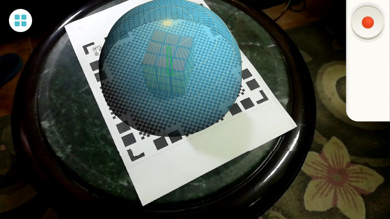
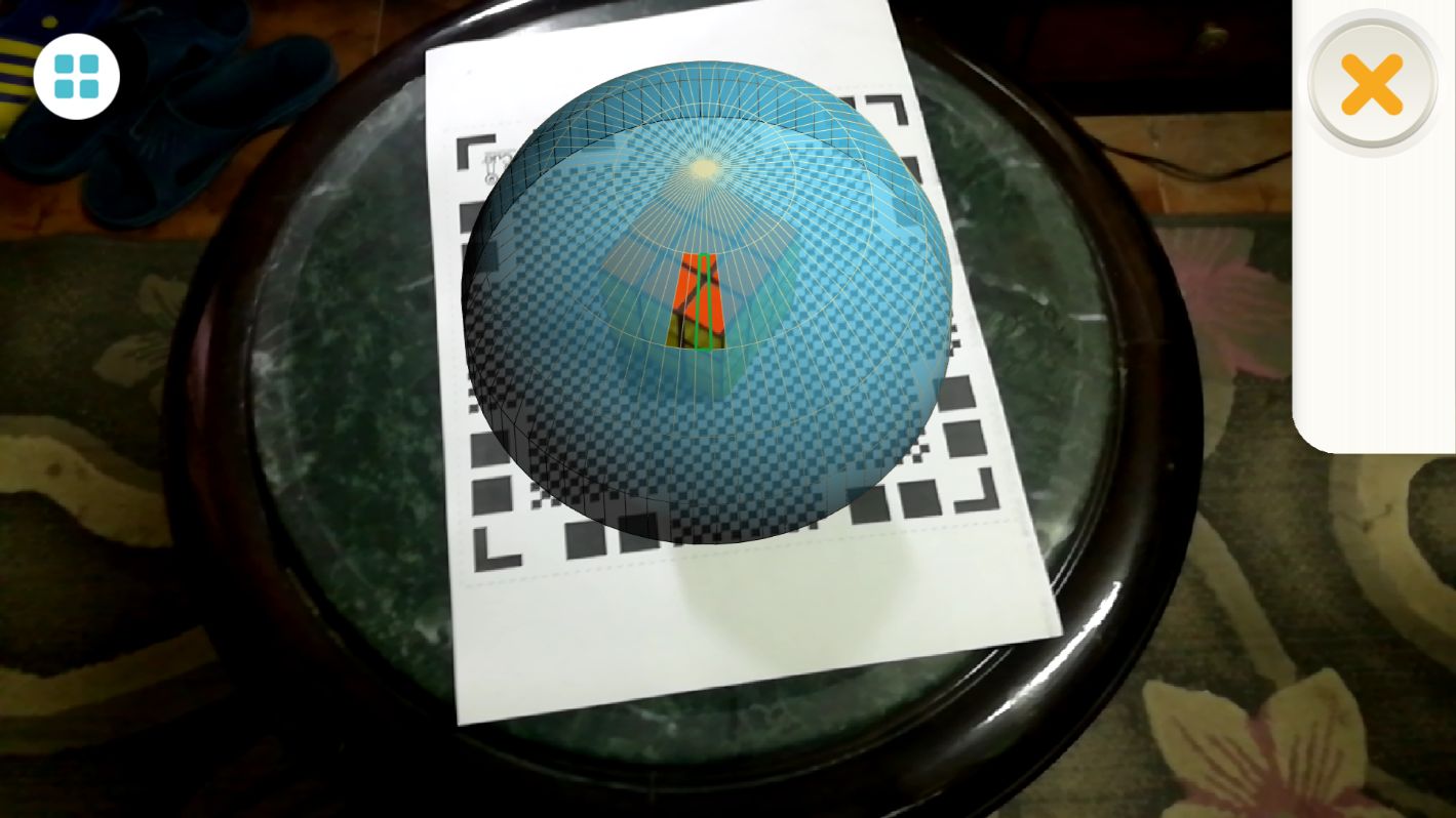
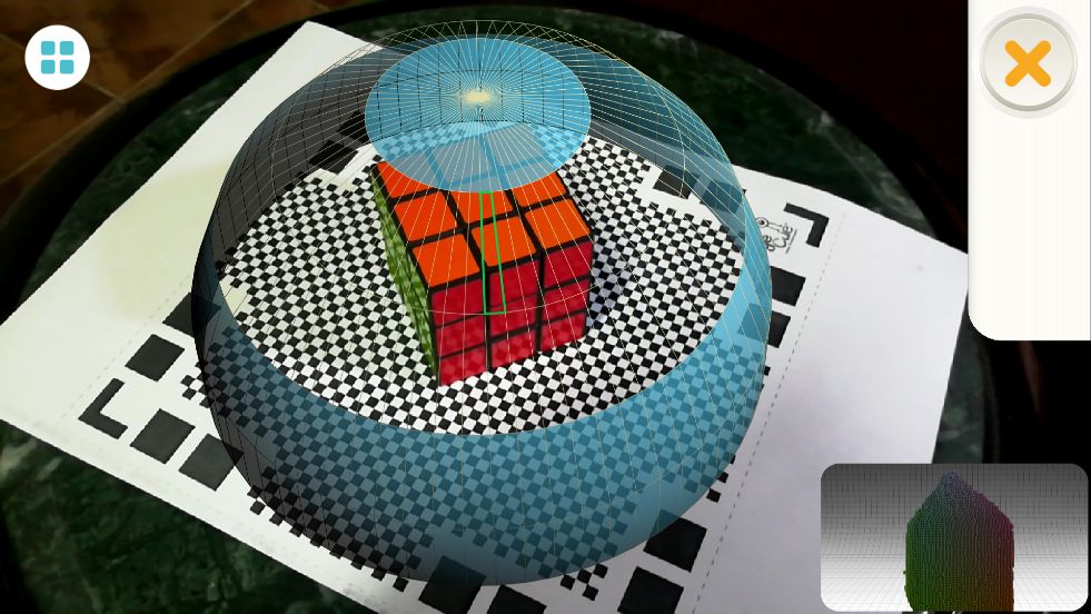
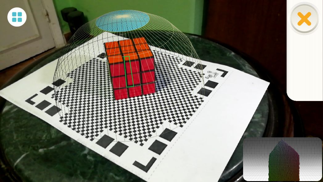
- After the entire dome disappears, the app starts to process the scanned object.
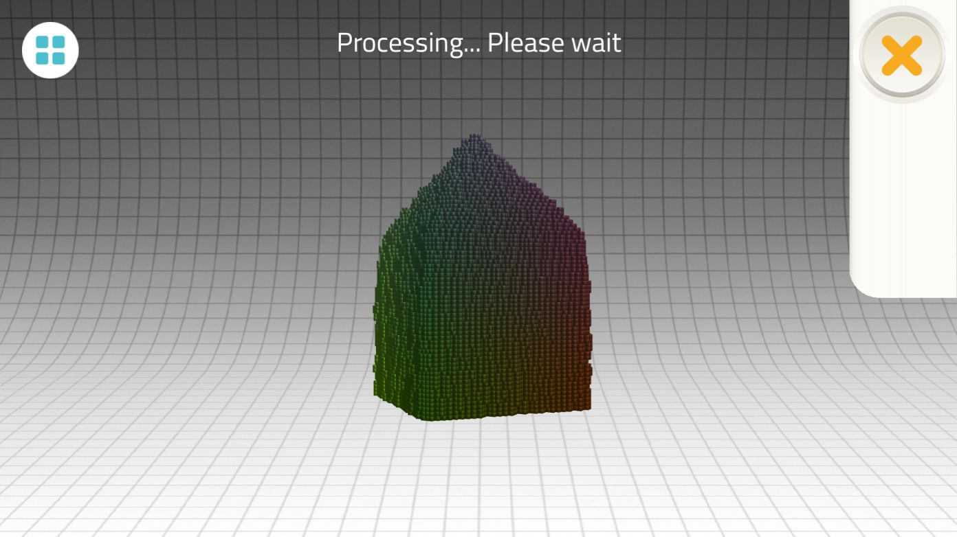
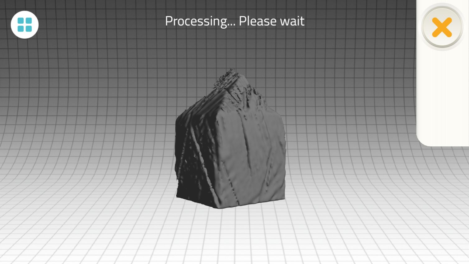
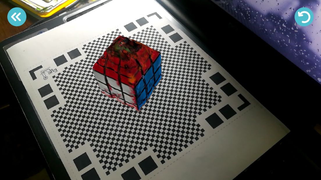
- After the app has done processing, the final object appeared. It had a weird pointy deformation at the top!
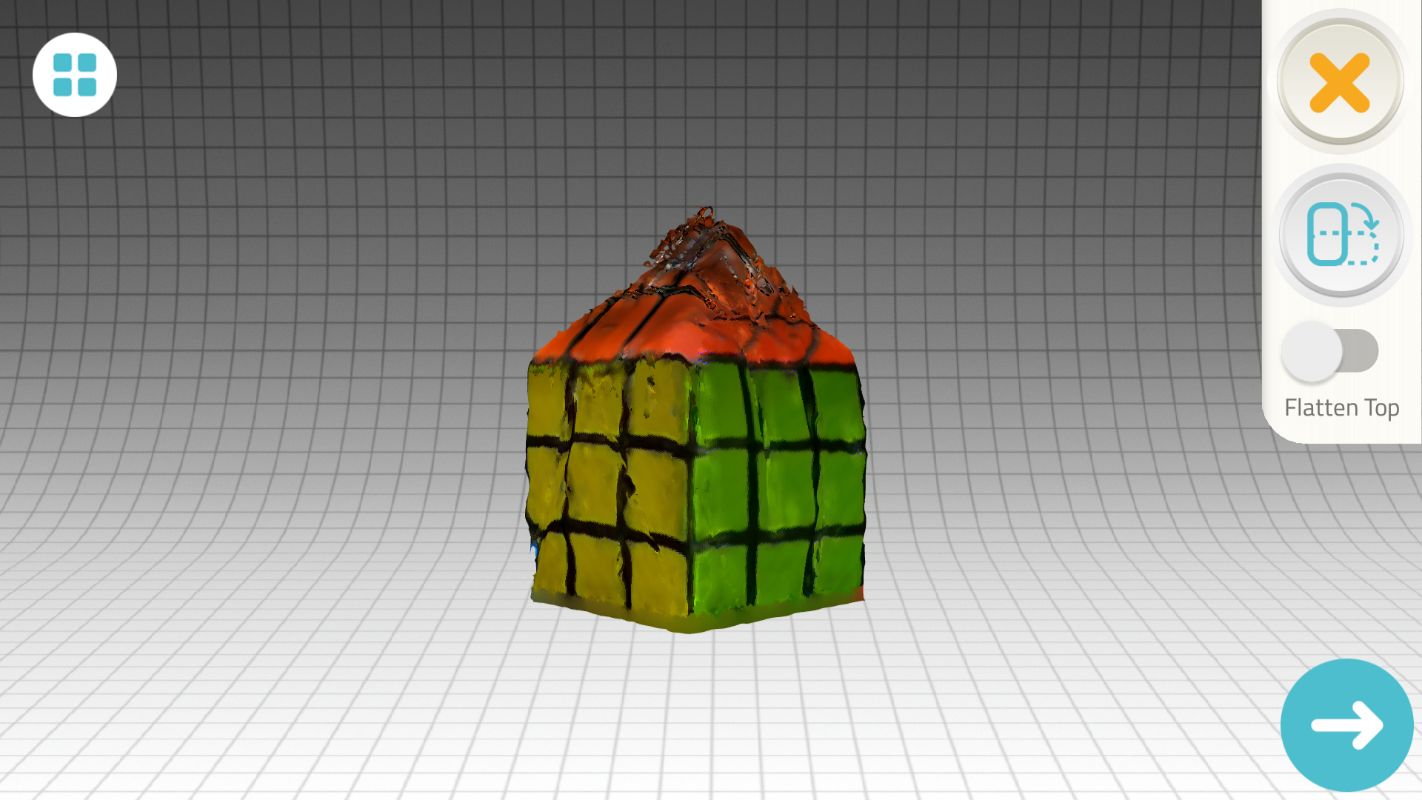
- But it seems that the app developers already know this defect in processing, so they added a feature to the app where you can "flatten" the top.
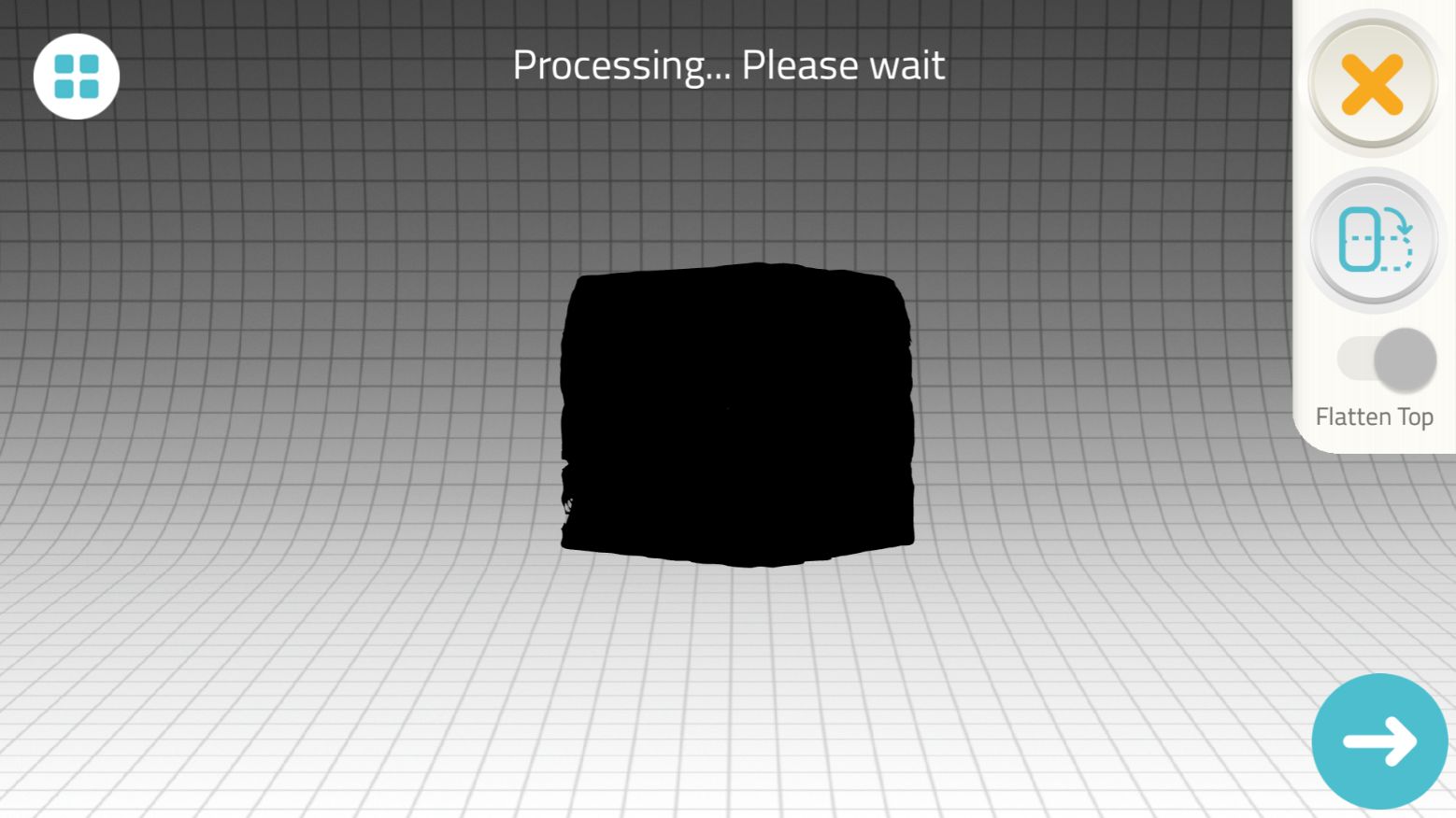
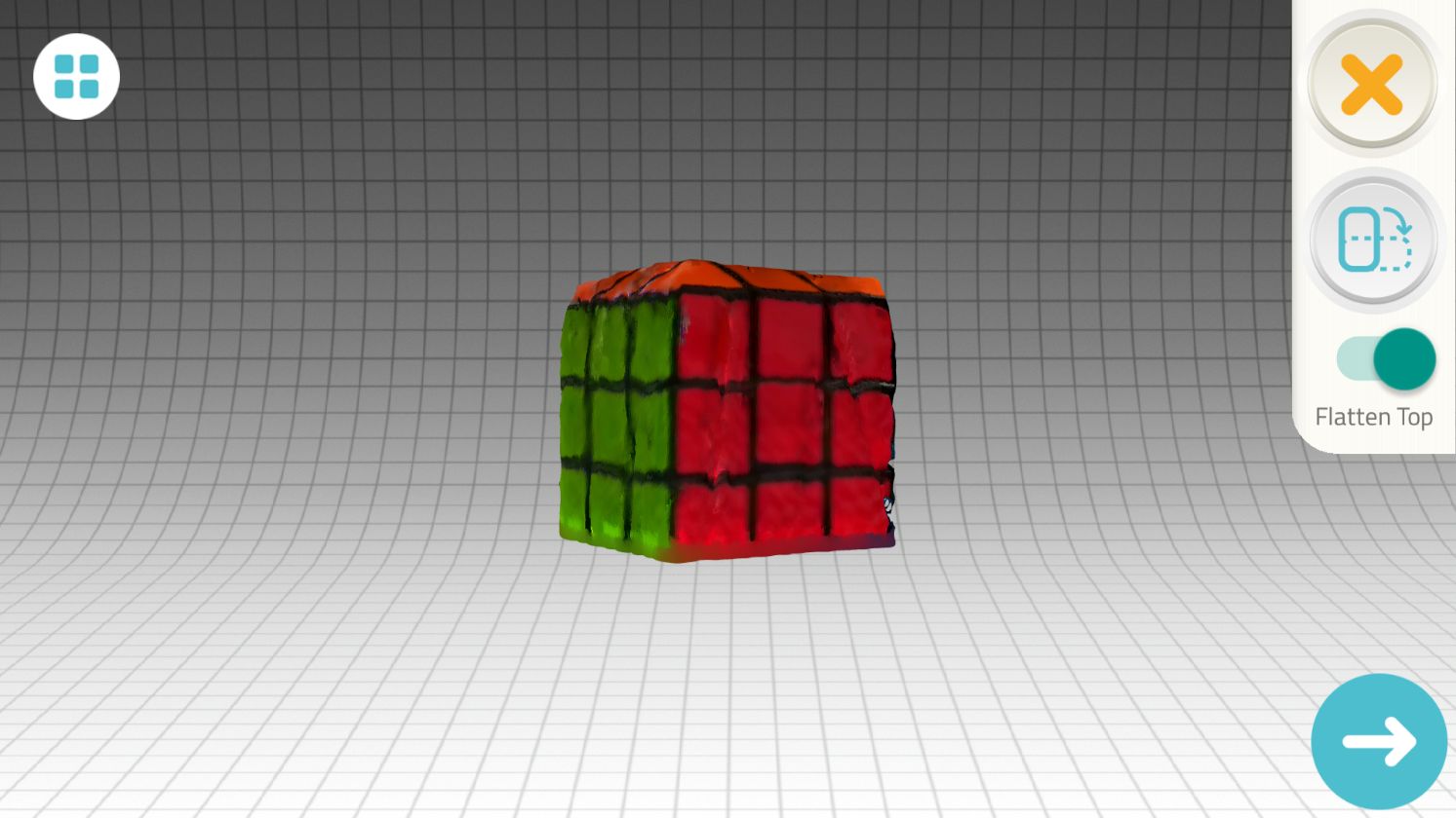
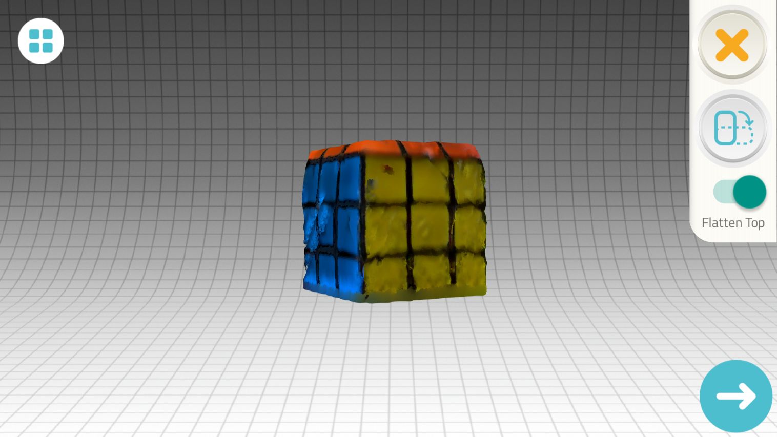
- The app also provides the option to manipulate the object and scan it from another pose.
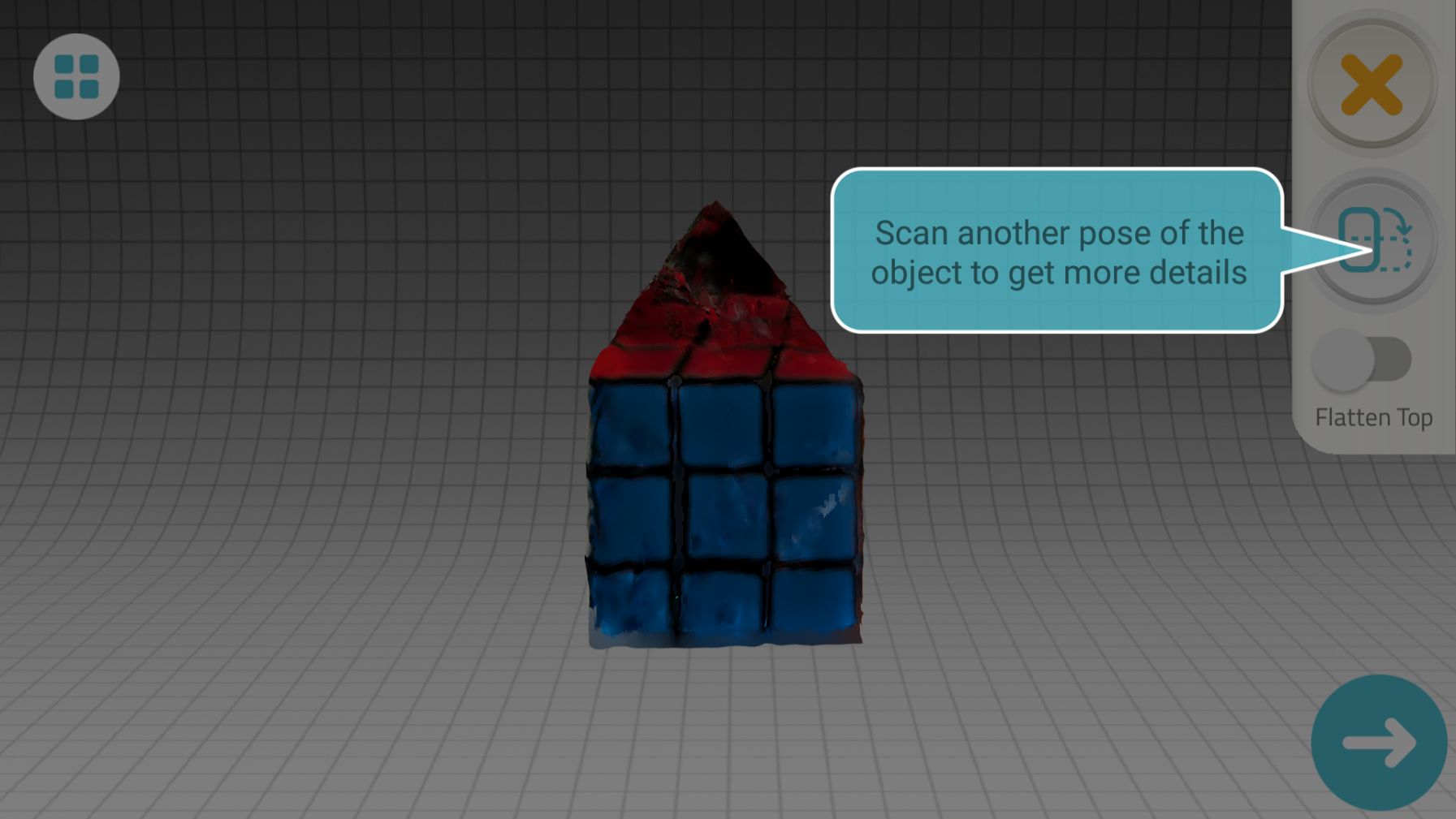
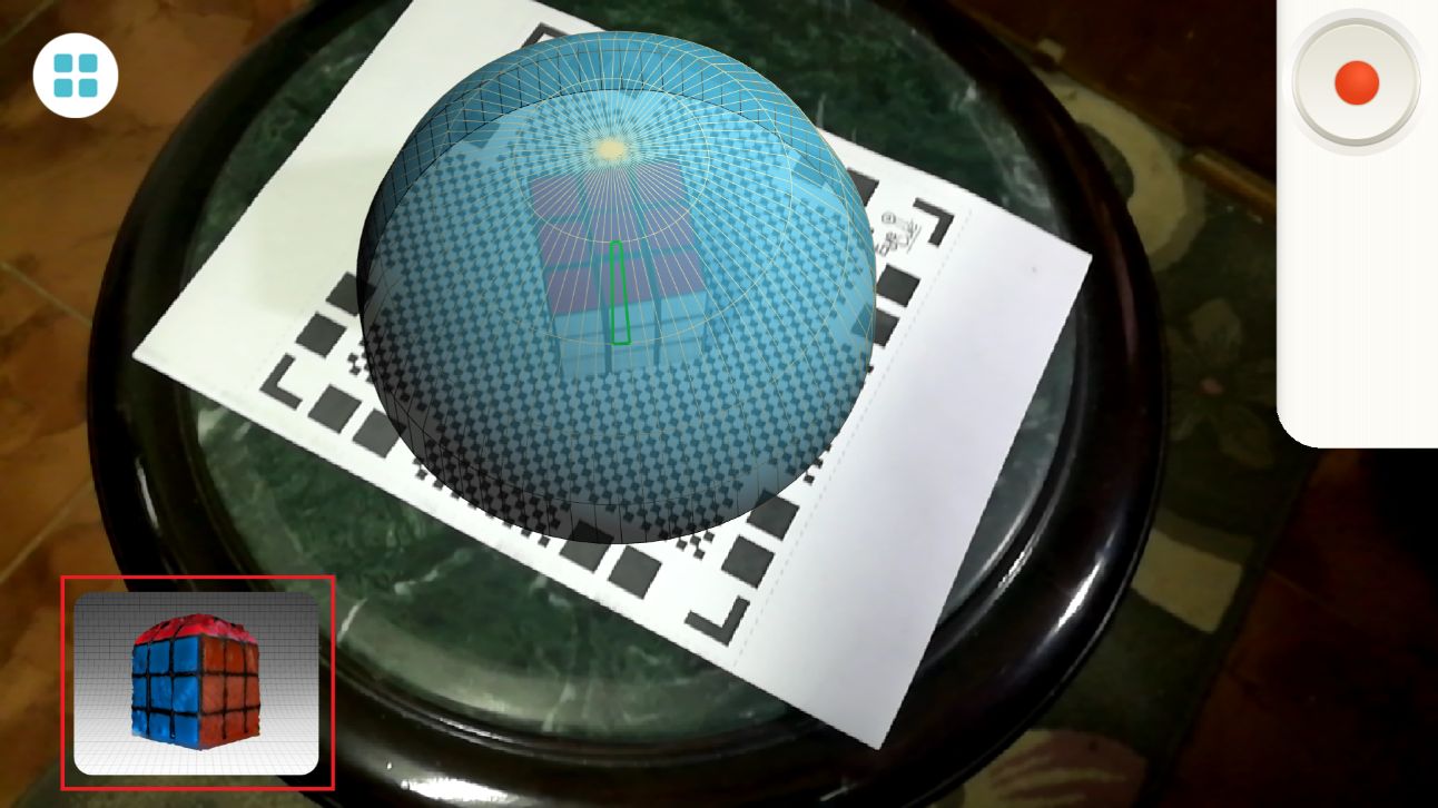
- The app then merges the two scans to provide an enhanced version of the object. However, I didn't notice any enhancement of any sort!
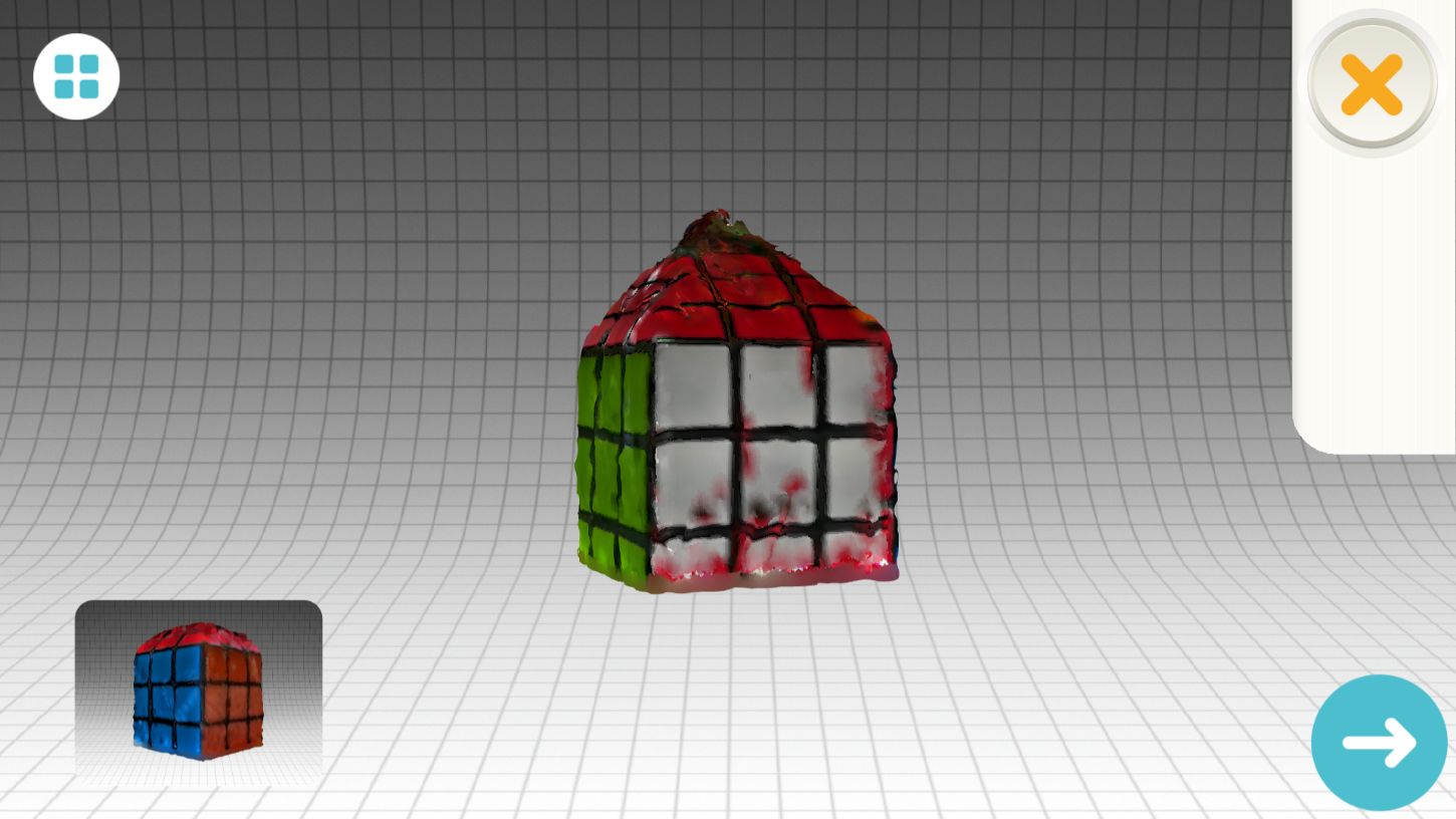
- Now that the object has be scanned, the provides me with options to edit it. However, the editing was challenging on a touch screen.
- I can for example clean it, but after cleaning I didn't notice change.
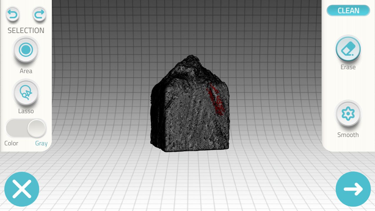
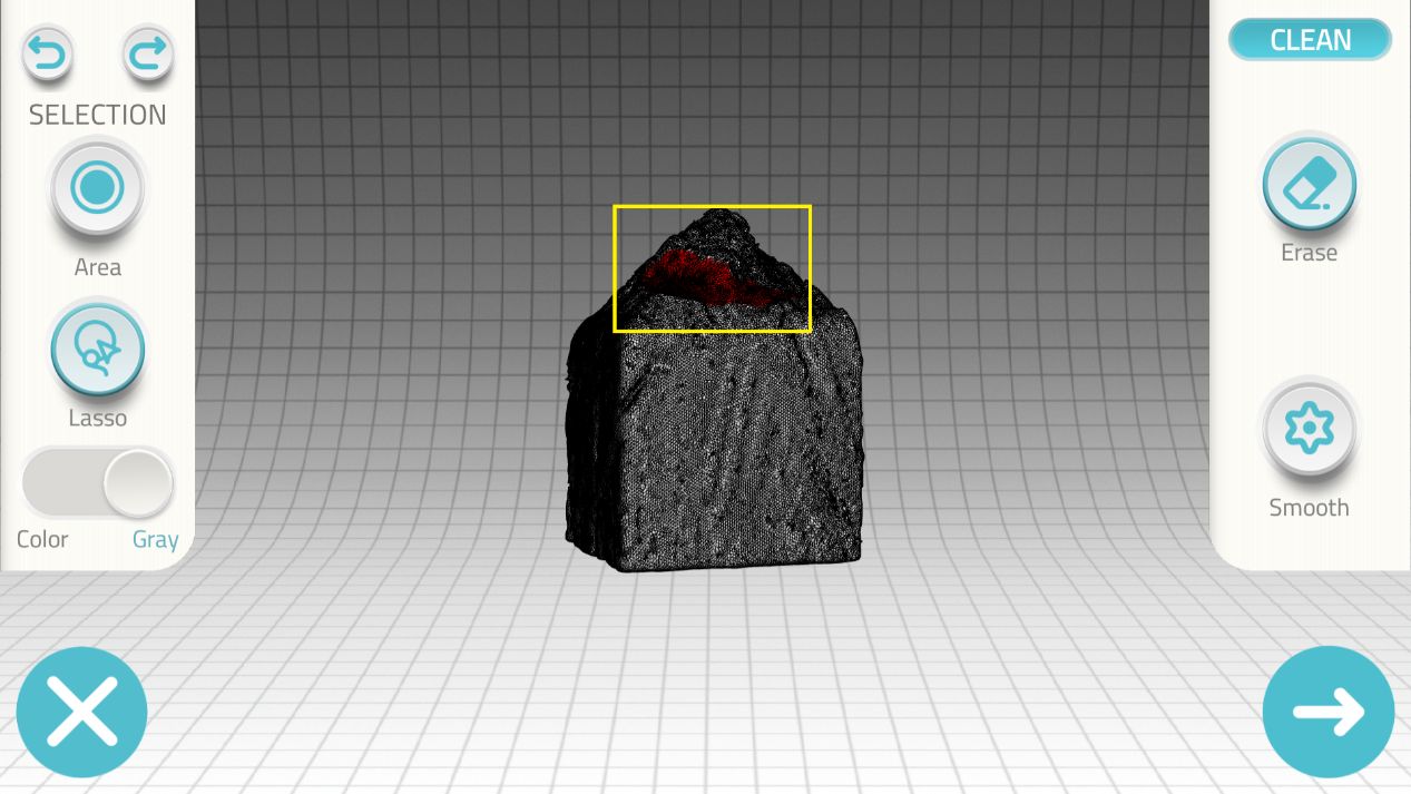
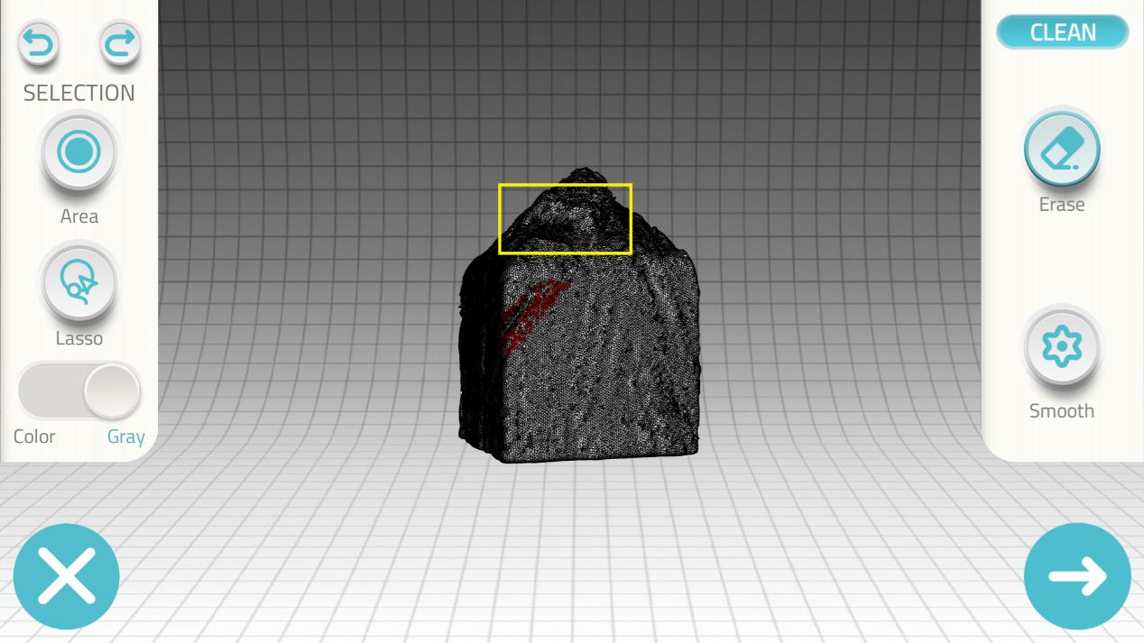
- There is another option to sculpt the object, which I also failed to preform on the touch screen.
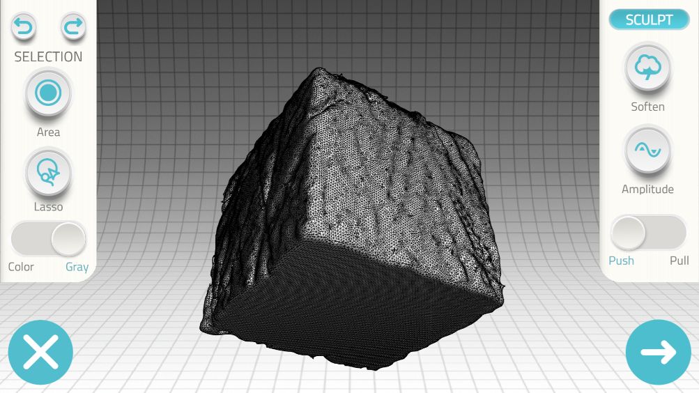
- And finally, there is an option "texture", where I was able to use a "color pick" tool to "paint" parts of the object.
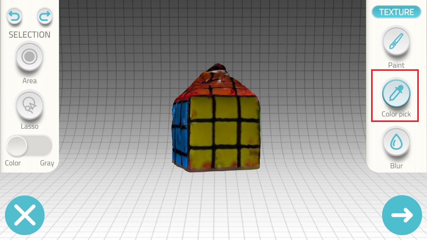
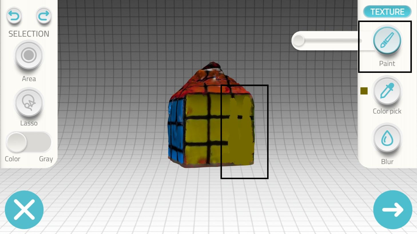
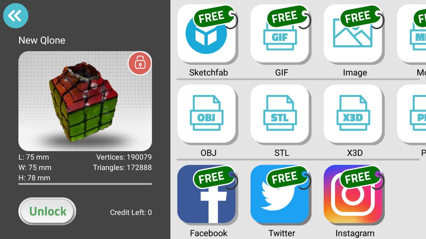
- Done with editing the cube! To export the scanned object the app requires you to purchase.
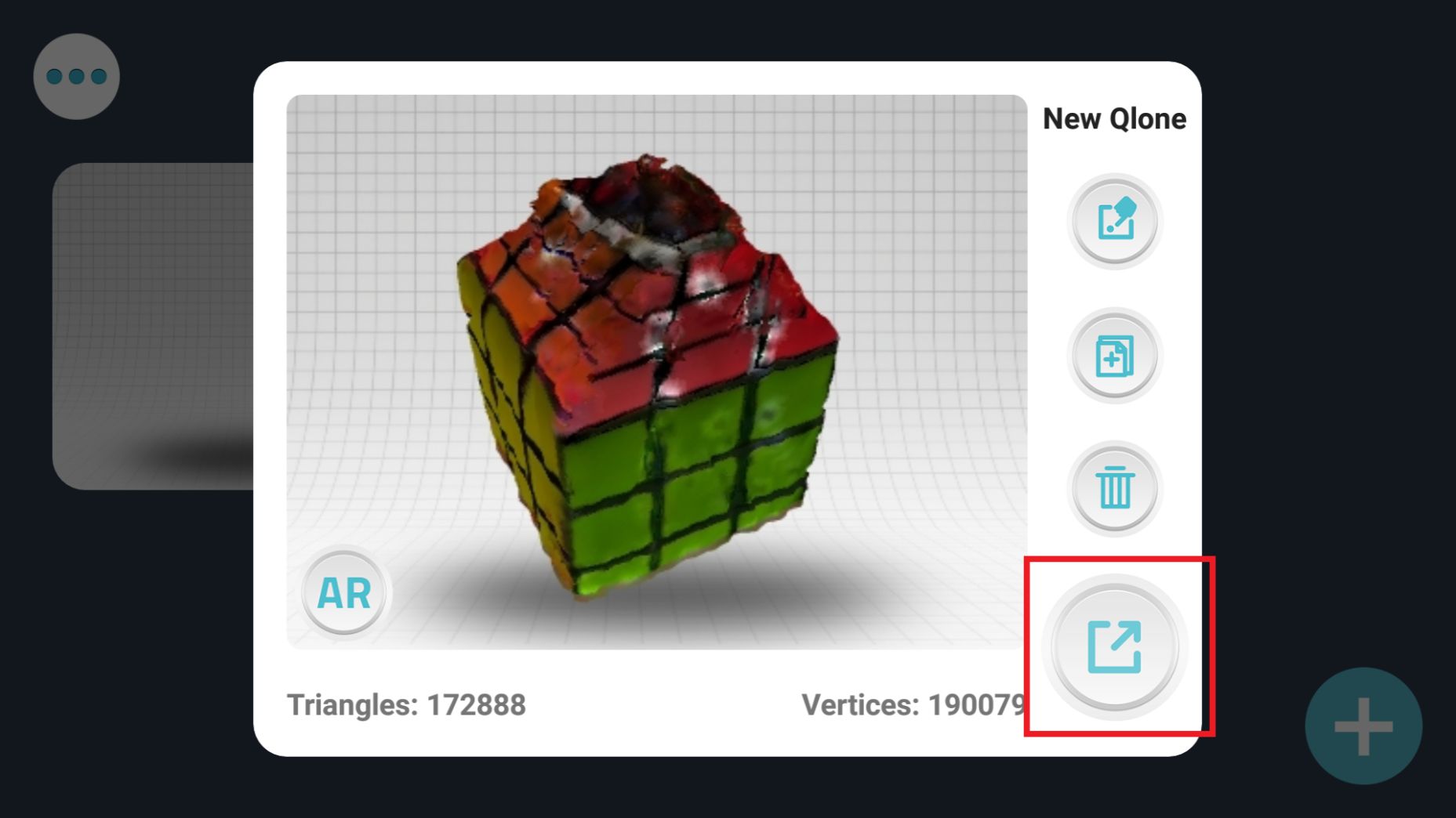
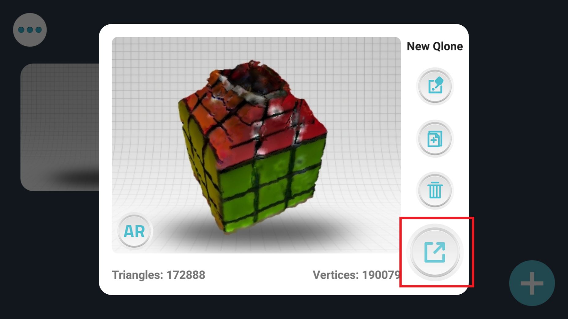
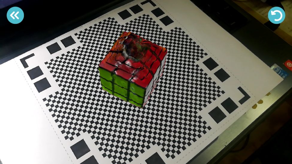
- Finally the app gives you the capability to project the scanned object back into reality again using AR technology. Just point the camera back at the mate to see the scanned object in the real world.
3. Test the design rules of your printer
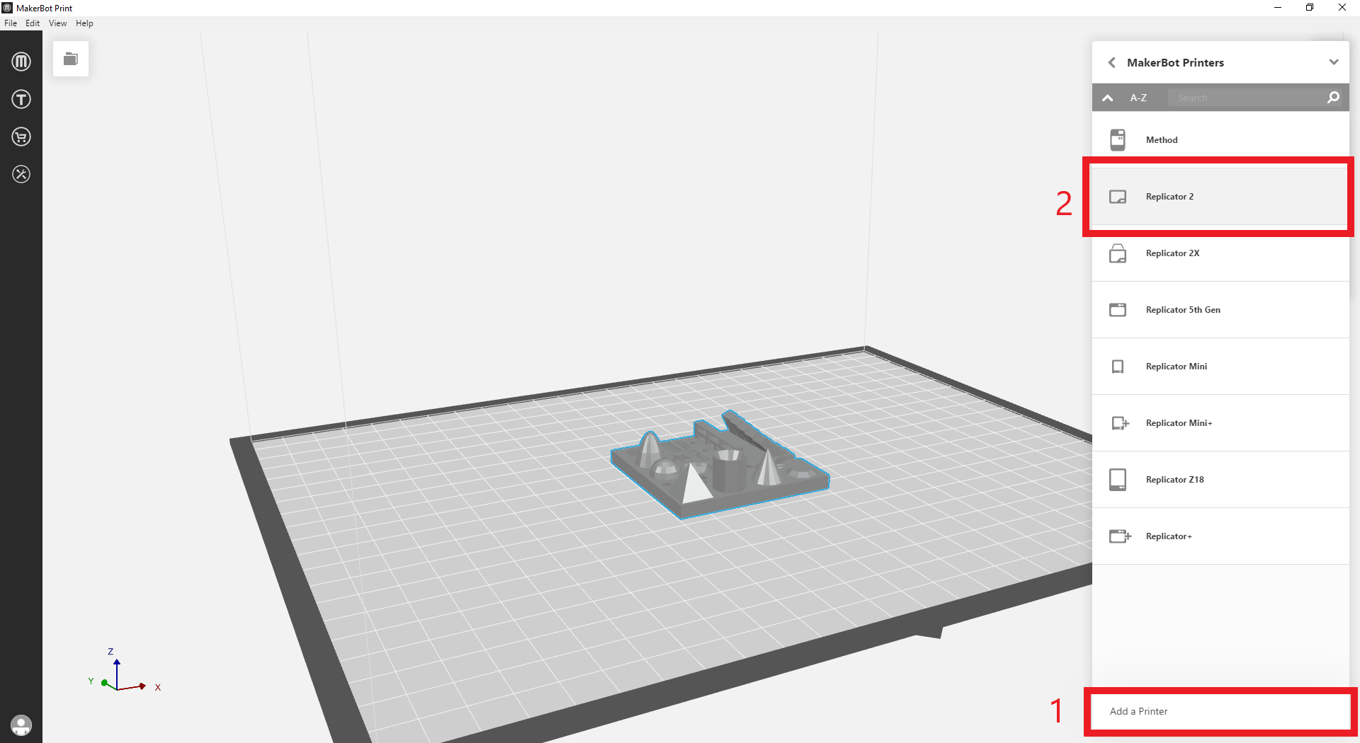
- For this group assigment, My classmate Nada and I divided our efforts, considering that she did her design tests for Prusa MK2 and MK3 printers, I decided to do my tests for the Makerbot Replicator2 printer at FabLab Egypt. In my investigation, I focused on testing 4 design parameters: Dimensional Accuracy, Overhangs, Bridging and Retraction Performnace.
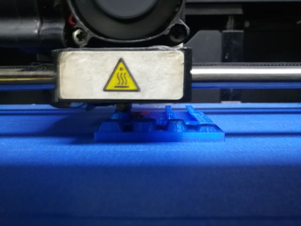
- For this purpose, I downloaded a test part from thingiverse, the part is designed to test for various design features including the four that I'm focused on.
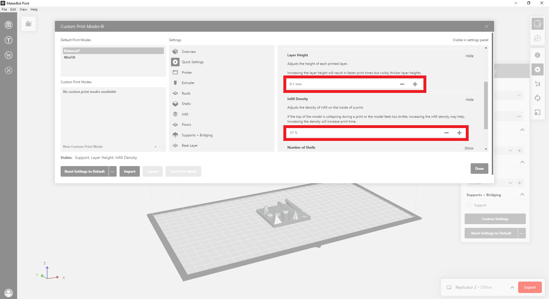
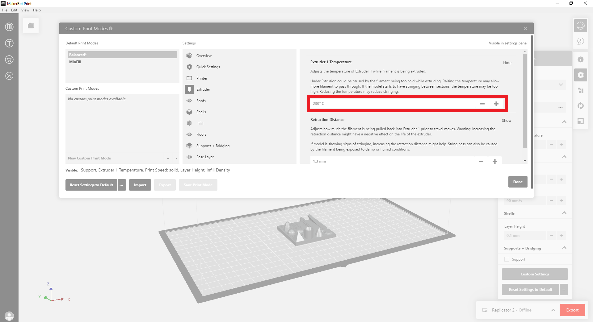
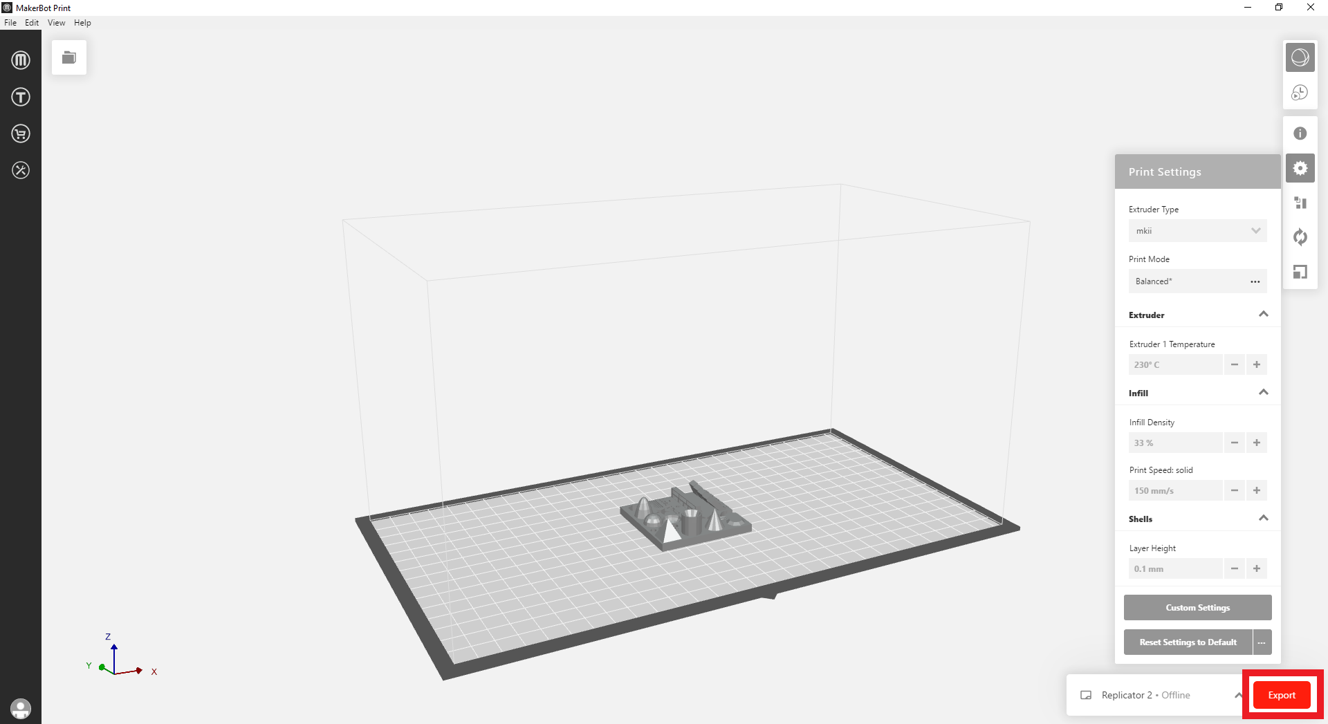
- I imported the test part in Makerbot software to set the printing parameters. The designer recommended the following printing parameters: 33% infil , 0.1 mm layer height, and printing speed between 60 to 200 mm/s.
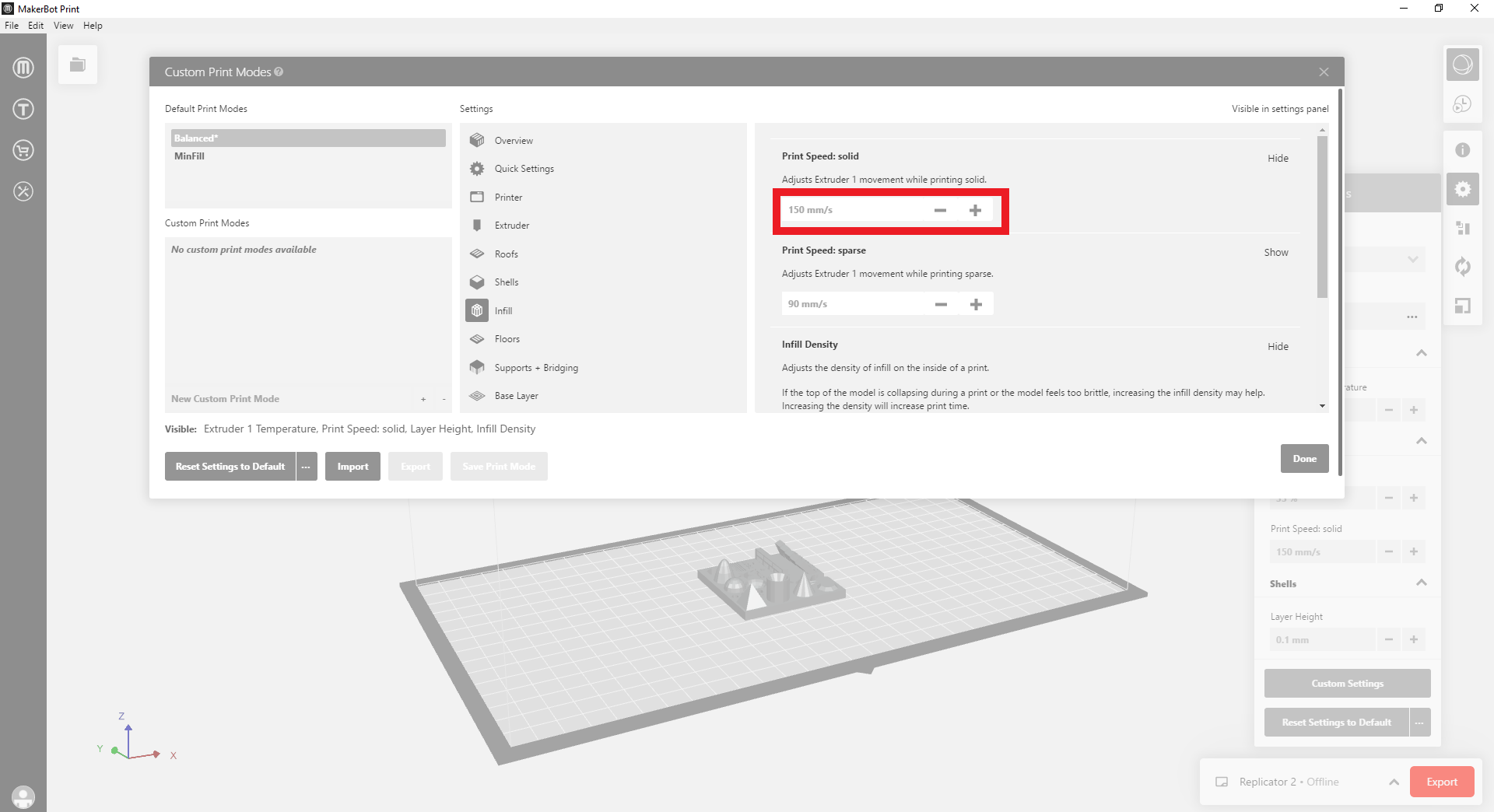
- I used the recommended settings for the temperture at 230 degrees
- I finally exported the gcode for Printing
3.1 Dimensional Accuracy
- Starting with testing for dimensional accuracy, I measured the length, width, and height of the object, and compared them to the dimensions.
- The original design dimensions are: 50x50x4 mm, whereas the printed object dimesnions were: 49.59x49.57x3.83 mm
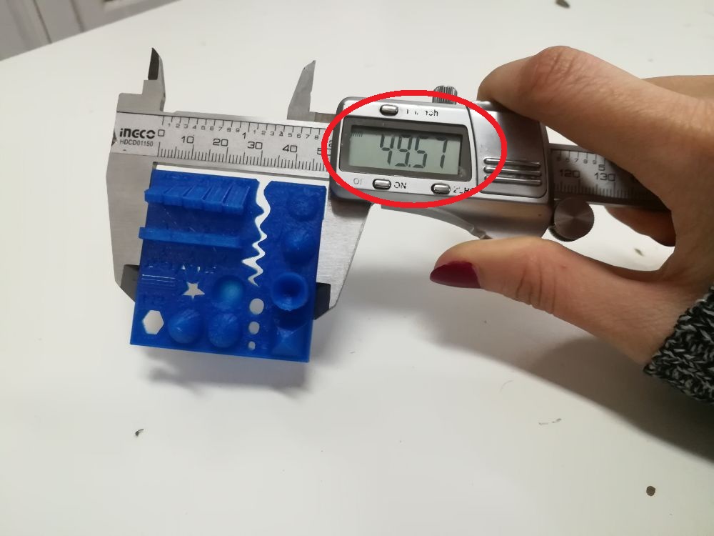
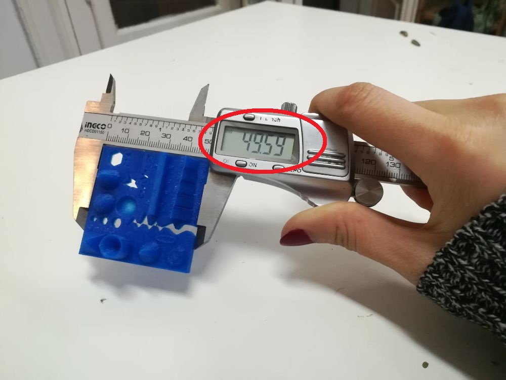
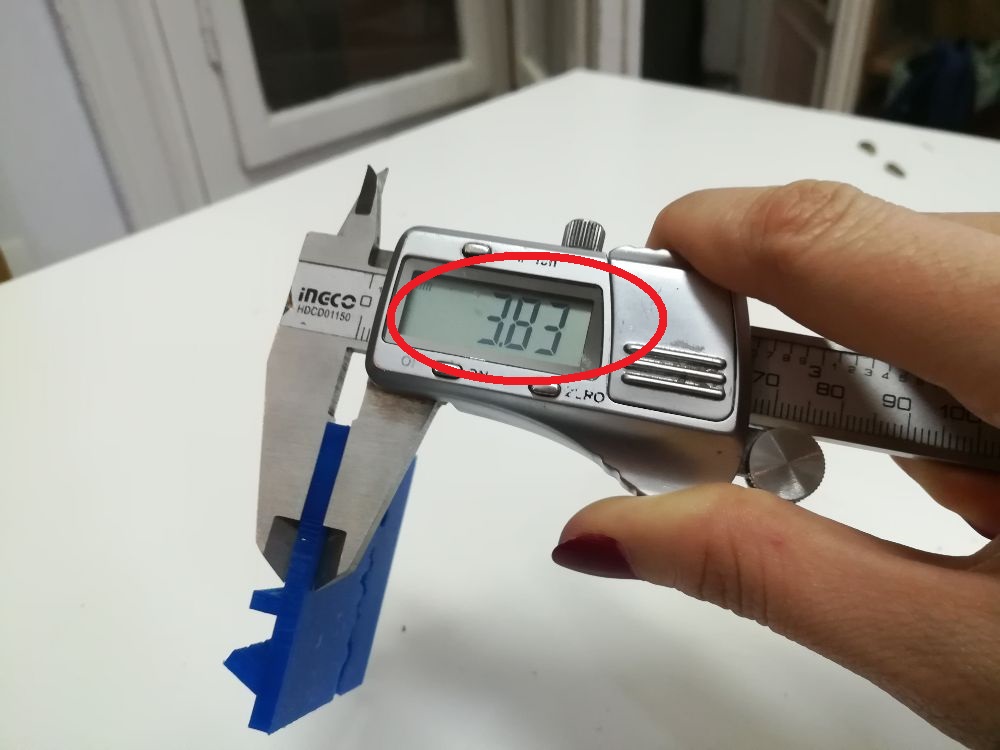
- I concluded from this test that the dimensions are 0.2 to 0.4 mm below the actual. There are several factors that affect dimensional accuracy, one of which is the tension in the belts, loose or tight belts can lead to inaccurate dimensions, the belts have to be tight enough so that the gears doesn't slip and cause inaccuracies during printing.
- There is also another obvious solution for this problem, which is actually accounting for this dimensional difference while designing,
3.2 Retraction Performance
- Strings can be a visible outcome of printing more than one part at once or if the print structure has wide gabs within.
- This can be a direct result of retraction length (how much the filament is retracted while moving from one part to the next), or printing speed.
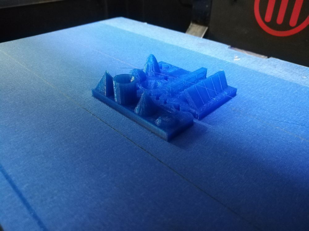
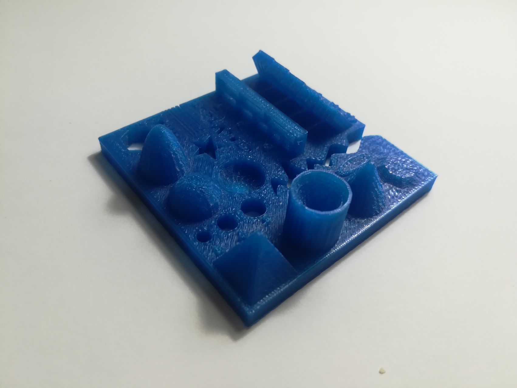
- In this particular test, the retraction performance was perfect with no visible stringing.
3.3 Overhangs
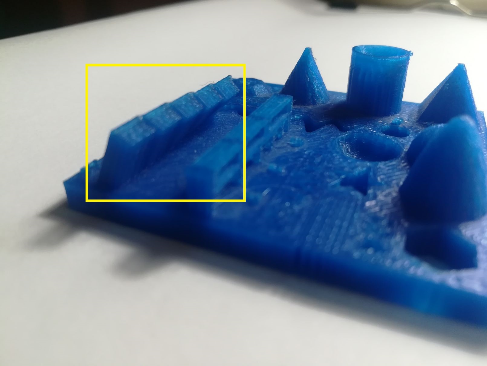
- Overhanging is basically having an unsupported material in the Z-direction. Most printers can achieve overhanging up to 45 degrees, others can exceed it.
- This test part is designed with overhang of 25°/30°/35°/40°/45°. The overhangs at all degrees looks good with no need for supports.
3.4 Bridging
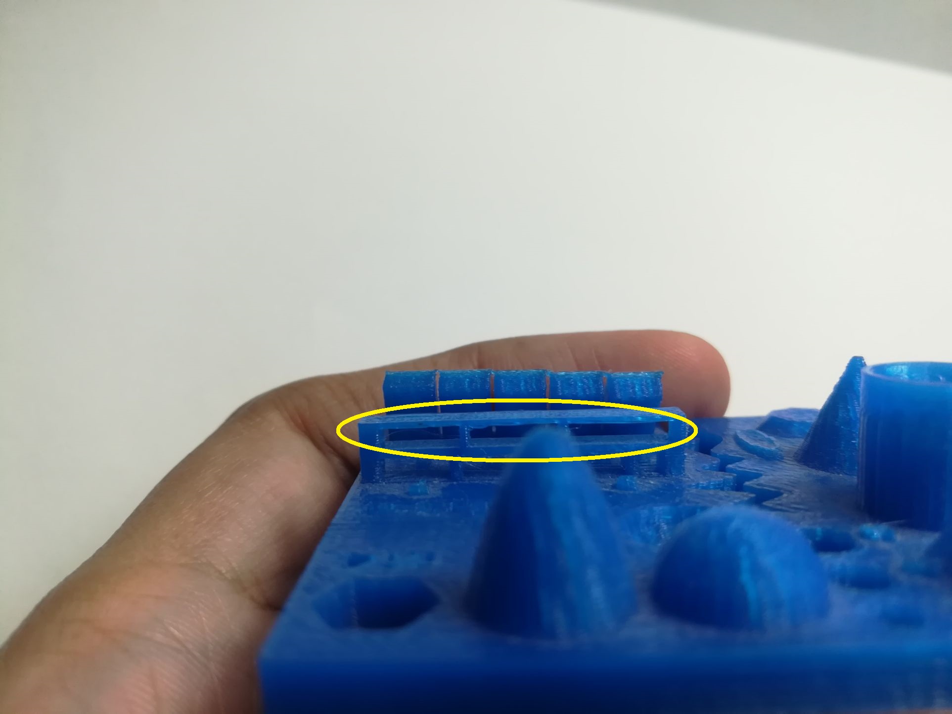
- Bridges are printed flat sections that cross open gabs in the model horizontally.
- For this test part, bridges spanned for distances of 2/3/4/5/6/7/8/9mm.
- I noticed that the bridges from 2 to 6 mm where good with no visible sagging stringes. However, bridges at 7, 8 and 9 mm, sagging is visible.
- This problem can be mitigated by lowering the extruder speed from 20 to 30 mm/s.
Design Files