3D scanning and printing
Assignments
#1 - Design and 3D print an object (small, few cm3, limited by printer time) that could not be made subtractively
#2 - Group assignment - Test the design rules for your printer(s)
See here
References
Lecture
This week is about 3D printing and scanning:
- How to design 3D virtual objects using FreeCad
- How to scan existing 3D objects
- How to prepare virtual objects to be physically printed
- How to print those objects
Recitation
Nothing planned for the week
Topics covered (course) Video recording (course) Students and Labs My filesLearnings
Using FreeCad to design objects in 3D
My target for this week is to design and to 3D-print a bearing. Usualy a bearing is made in metal and looks like this:

I started from a project I found here . The project is fully parametric. I found also another script-based method to build it here
- Draw a ball
- Draw two circle. Pad a ring from them, set some height, position n balls along the circle, with equal distance between them
- Once combined, the ball circle and the torus create a custom collar with place for the balls
- The following object represents the path that the balls will follow, inside the bearing
- The parts in green are the internal and external walls
- One method to get the grooves is to substract a tore from the internal and external rings
- We need an insert to add the balls once the bearing structure will be added
- Here is how it looks with the walls and the balls but there is an issue, there is nothing to enforce a fix distance between balls
- It is fixed when we add the collar...


Here is why I cannot use another tool (like a CNC) to make such a part: both the inner ring and the outer ring have a groove. The one on the inner ring (when not inside the outer ring) can easily by made using a lathe. The groove on the outer ring is internal and I don't see how we could make it using a CNC, even with a 5 axis CNC since there is no room for the tooling. MAYBE it would be possible using a lathe, with a custom tool but I'm not an expert in lathe. The internal colar is an even bigger challenge: in theory, it looks possible to drill each slot one at a time and then to turn the wheel and drill the next slot but we would need to be VERY carefull with the angle. 3D printing looks to be the best process to achieve it
I do not plan to print the balls, it should not be perfectly round and it could not resist to friction for a long time.
Using a slicer to prepare (virtual) objects for printing
(from this site ) A so-called slicer takes a 3D drawing (most often in .STL format) and translates this model into individual layers. It then generates the machine code that the printer will use for printing.
A slicer program allows to calibrate printer settings for various types of "areas to print", like: extrusion speed (rotations / minute), head speed, temperature,Fan on/off. Furthermore, the program allows to define: wall thickness, fill patterns, xtrusion speed, head speed and temperature per type of are,...
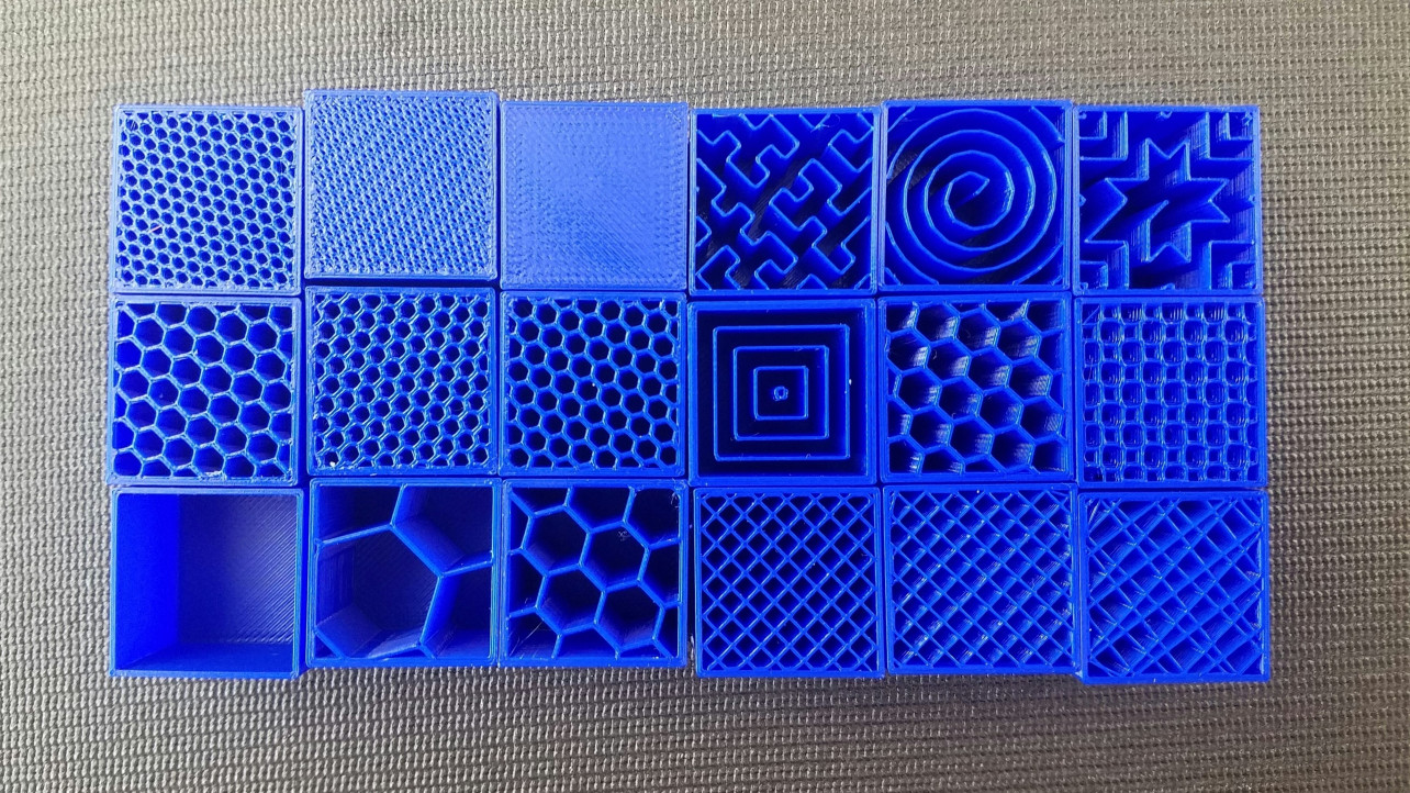
Infill density is the amount of filament printed inside the object, and this directly relates to the strength, weight and printing duration of your print. Different 3D print infill types, or infill patterns, can affect the object's final strength without changing the print's weight or filament used. Here are some examples:
I know two slicers but I'm used to Cura . The other one is Slic3R
Once the STL file is opened within Cura and sliced, here is how it looks like (I tuned the settings to see the result approximatively the half of the printing process so you can see to each layer is added)

My initial plan was to use the Ditto Pro at echoFab but I saw that almost everybody was using the Prusa MK3 and I changed my mind. By default, Cura has not built-in configuration for that specific printer. I switched to Slic3R
It is easy to adapt and the layout is similar

There is a way to see the internal structure by playing with the cursor that represents the time

The following view is intresting because it highlight a potential issue. In my object, there are three moving parts and the distance between those parts should be minimal to get a working bearing but if it is too small, the parts will glue together.

Using a 3D printer to make virtual objects real
3D printers can be either controlled through a small on-board control screen or through a (USB) interface with a computer or through both. User interface/control software allows a user to send a machine code file from the computer to the 3D printer, change some parameters on run time (e.g. speed, flow and temperature), and move the print head manually around the x/y/z axis.
Current low-end 3D printers extrude plastic like ABS or PLA from filament. The filament is pulled into the extruder and heated in its nozzle (hot end) and finally deposited. The extruder (also called print-head) will move while extruding, or move (or jump) without extruding.
3D printing can take a long time, hours.. Hopefully, there is an SD card reader and it is easier to copy your file (G-code) to an SD card and to insert it into the printer.

3D printers have limitations. Just consider this little Yoda (I know, Yoda is always little..). Just check the ears and how the printer has been pushed to the limit. There are no supports, i.e each layer relies only on the previous one and we cannot print on nothng. Once the figure was printed, some cleaning was required to remove a few filaments that did not glue correctly and were hanging here and there, espacialy under the ears.


One way to bypass that limitation should be to use a printer with two feed, one with PLA and another one with another material that I could dissolve (in water or any other solvent, depending on the material).
To come back to my bearings, here are my samples. The one in black are printed using my 5 years old no-name printer and the white one comes from the Prusa MK3. Resolution is really better with the latest


I think I met the requirements: my object cannot be manufactured using a CNC (mainly due to the internal grooves, there is no room for the cutting tool). It could be manufactured in a mold with platic injection but this is not an equipment we have access to. The next step would be to print the smalls balls that are inserted within the collar. Currently, I m using metal ones.
Using a 3D scanner to build (virtual) objects out of real ones

My first attempt was to scan a green apple such as this one

It did not work. The software does not manage it well, maybe because there is some wax on it. I tried with a black background, I put it on a chair, on the top of a glass. No luck .. The scanner does not get a grip on it. The green apple ended in my lunch..
My second attempt was successfull and the outcome is shown on Francis web site.
My third attempt was not ok until Francis told me I had wrong settings ("face" vs "object"). The targeted object was a nice pink toad originally printed on a 3D printer. Here is the outcome:

And the nice toad is now sitting on the virtual 3D printer bed, ready to be cloned !

How to get a better result ? I found out this this site where there are some great advices on how to do a better job. To summarise:
- The scan quality will greatly depend on the lighting conditions. Maybe it could justify some investment in our FabLab
- Using a turntable has the big advantage of not having to walk around the subject
- Shiny objects (as my green apple ! )cannot be 3D captured in their original state. But if you’re just caring about the geometric shape and not the esthetics, there is a solution for this: making the object opaque and matte. This can be done using a a matte, light-colored spray


Achievements
3D printer
I cannot say I learned it because I had one at home but I learned what a better printer can do
3D scanner
My first try with such a tool. I mostly learned what does NOT work, I finaly got a decent result and I found (but did not experiment) ways to get yet better results. I suggest our Lab Manager to build a nice setup with better lighting and a turning table for this tool at echoFab
Capstone
#1 - Figure out how 3D printing could contribute to the final project.
The enclosure for my final project has two parts: the bottom and the cover. For the cover, I would like to have a clean finish, as smooth as possible. The bottom is less visible. For the moment, my thinking process is the following:
- Bottom : it is basicaly a 10cm * 10 cm * 7 cm box. I tried to make it with the laser cutter and it looks ok for me. Next step is to use acrylic instead of wood and to tune a little bit the fitting (kerf was not well taken into account in my first attempt)
- Cover: I'm waiting for the "casting and molding" course to give the process a try. I will use the CNC to create a positive, than build a mold and finaly mold id.
- Currently, there is nothing obvious I plan to build with the 3D Printer but I'm sure I missed details.