Embedded programming

week 9
March 13, 2019
This week, we have to read a microcontroller datasheet and also to program our board for week 7 to make it do something with as many different programming languages
and programming environments as possible.
Read the datasheet
The first step before you want to program a microcontroller is to read the documentation in the datasheet. All electronic components have a datasheet directly from the manufacturer. It is in this document that we find all the information possible on the component.
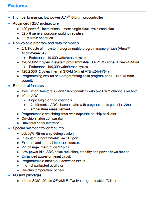
Here is the datasheet of the attiny44
To begin we can see that the datasheet is not only for attiny44. Sometimes, one component can be very similar to another and that is why the manufacturer groups them together in the same documentation.

It is easy to find the important information on the first pages to get an idea of the functionality of the part. I was really surprised that it could have all these features in this little microcontroller. This is the first page of the datasheet.
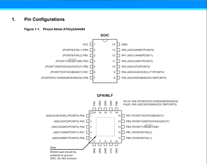
Here again in the first pages (in our case page 3), we find the pin configurations. In most cases the components have several formats. In our case the part is in SOIC and QFN/MLF format. I noticed that one format had more pine trees than the other. After reading the note, I understood that these are pins that are used for nothing other than soldering the component to the circuit. They are not connected.
By reading the datasheet I learned more about the possible features than how to use them. I believe that in all datasheet readings, it is important to know the potential of our component to know what is available. When a feature interests us, it is at that moment that we can read more deeply to understand how it is used. I learned that there were two counters for the PWM. There were 12 ADC (Analog to digital converter), a watchdog timer and an external and internal interrupt sources. What surprised me the most is that there is a temperature sensor directly on the chip. Always handy to know if our microcontroller is overheating. For such a low price I am surprised to see what it can do.
Here is the datasheet of the attiny44
To begin we can see that the datasheet is not only for attiny44. Sometimes, one component can be very similar to another and that is why the manufacturer groups them together in the same documentation.
It is easy to find the important information on the first pages to get an idea of the functionality of the part. I was really surprised that it could have all these features in this little microcontroller. This is the first page of the datasheet.
Here again in the first pages (in our case page 3), we find the pin configurations. In most cases the components have several formats. In our case the part is in SOIC and QFN/MLF format. I noticed that one format had more pine trees than the other. After reading the note, I understood that these are pins that are used for nothing other than soldering the component to the circuit. They are not connected.
By reading the datasheet I learned more about the possible features than how to use them. I believe that in all datasheet readings, it is important to know the potential of our component to know what is available. When a feature interests us, it is at that moment that we can read more deeply to understand how it is used. I learned that there were two counters for the PWM. There were 12 ADC (Analog to digital converter), a watchdog timer and an external and internal interrupt sources. What surprised me the most is that there is a temperature sensor directly on the chip. Always handy to know if our microcontroller is overheating. For such a low price I am surprised to see what it can do.
question...
I wonder if it is possible to calibrate an oscillator. This question came to me at week 7 in the asignement group when I was measuring signals and after reading the datasheet. In the code I had a delay of 100 ms and I really got 106 ms. So I would like to know if there is such a thing as knowing how to calibrate an oscillator.Program our board
Program with Arduino IDE with C
Prepare Arduino IDE
To get started, I decided to use the Arduino IDE because it is compatible with Atmel processors. So here is the GUI of the program.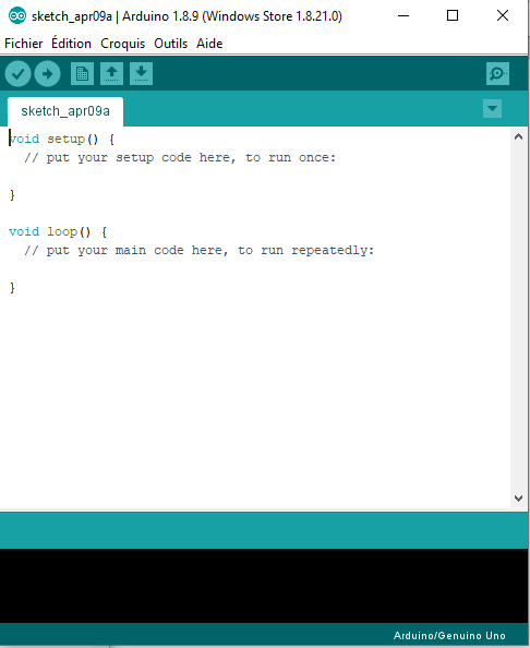
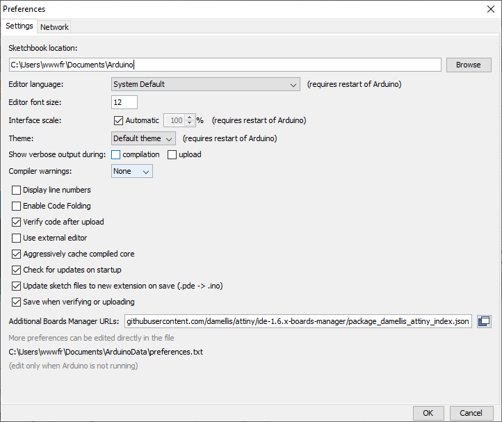
To have the option to program the Attiny44, simply install a small add-on in the program. To do this, you have to go to the file tab and then preferences. Copy the following link in the Additional Boards Manager URLs.
link: https://raw.githubusercontent.com/damellis/attiny/ide-1.6.x-boards-manager/package_damellis_attiny_index.json
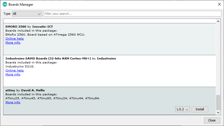
Then, we go to the tools tab, and then to boards - boards manager. We go to the bottom of the list and we have to install attiny by David A. Mellis.
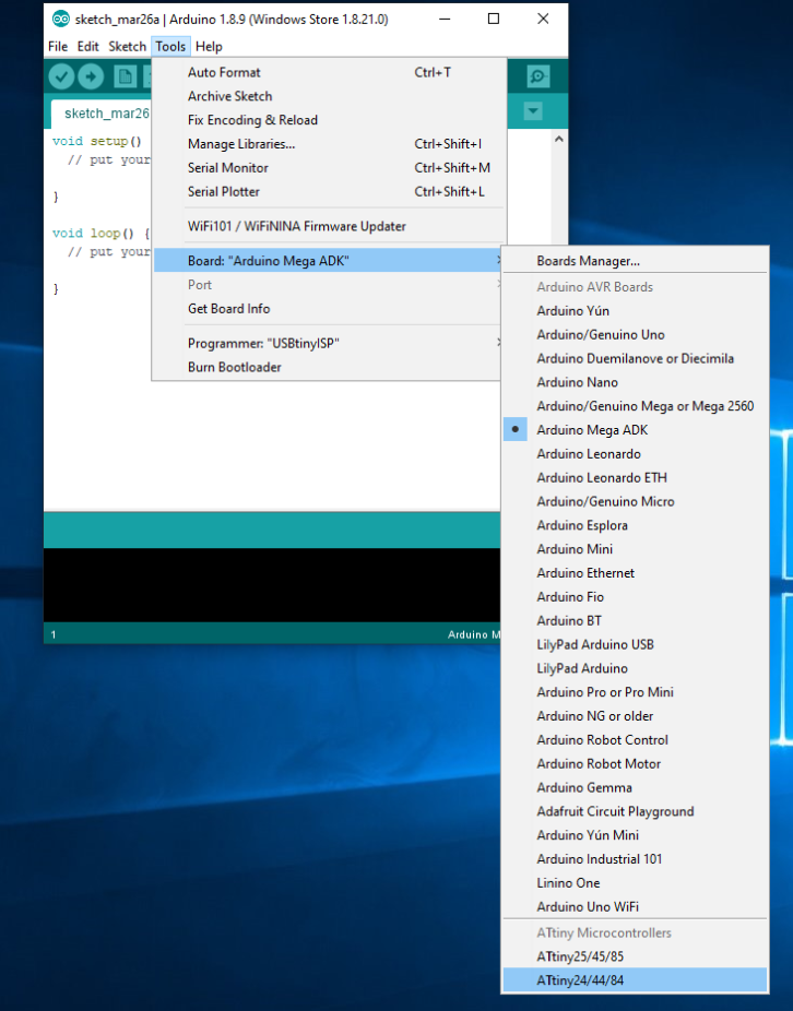
Now in the choice of boards, you should see the ATtiny44. Select it
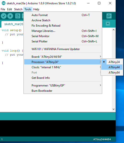
Now select the ATtiny44 processor.
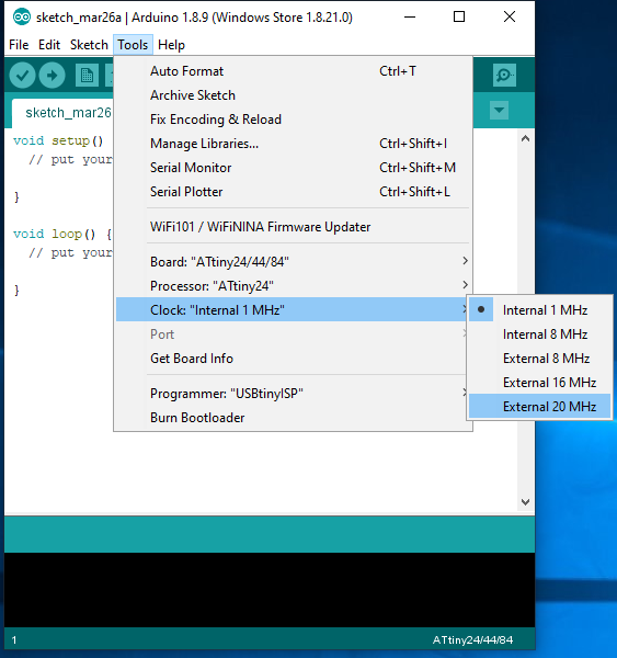
Now select the clock speed which is in my case 20 MHz.
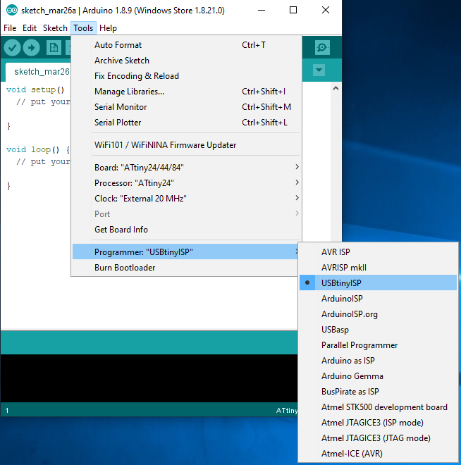
Finally, we select the programmer we use. In my case it's the USBtinyISP
Program our board
When I tried to program my board for the first time with an example from Arduino IDE, I had this error.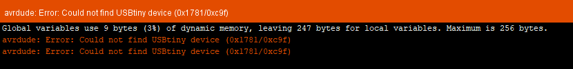
If you ever see this error, it is because you did not install the drivers for the AVR programmer & SPI interface. Just click on this link to download and install the driver.
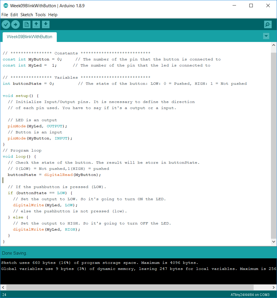
This is the program I wrote to test the programmer. All comments are in the program to understand how it works.
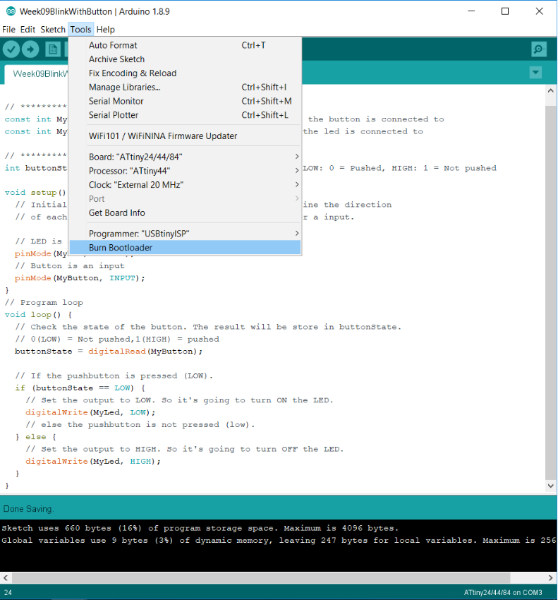
The first time I programmed the attiny44. I noticed that there was a delay when I pressed the button. So I programmed the microcontrollers with the blink example to make the LED blink every one second. I noticed that the time was 20 times longer. I noticed that the clock settings were not good. To solve the problem, I burned the attiny44 bootloader directly into the Arduino IDE.
Result
Program with Makefile with C
Create the makefile
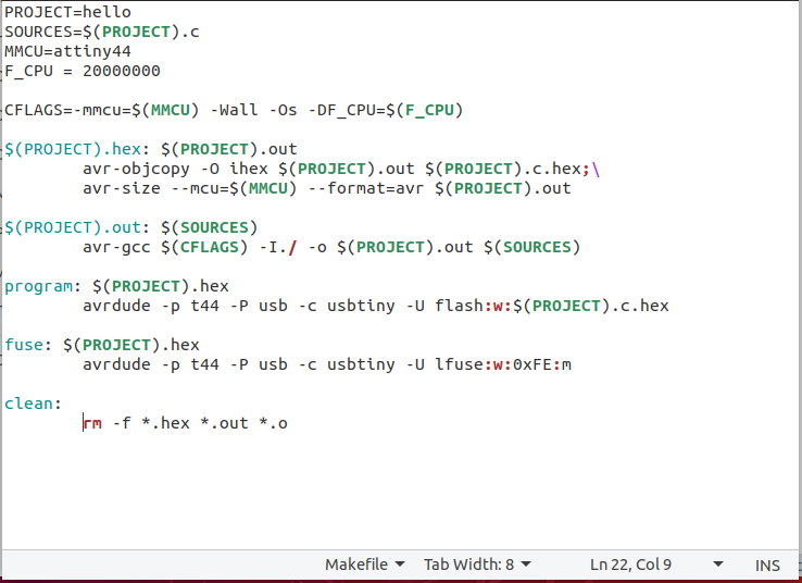
A makefile is mainly used to launch several commands by typing a simple word preceded by the make command. In this context, we use the makefile to compile the code, set the right fuses and program our microcontrollers. I used this site to better understand the orders as well as students from previous years.In my makefile, I have defined the name of my project and my file for compilation. It is also important to define the microcontrollers and the CPU frequency.
The first two lines are used to compile the code and create files for programming (.hex,.out,.o).
The three commands of the makefile are:
make: to make all the files for the programmation.
program: which is used to program the microcontrollers.
Fuse: that is to fuse the microcontrollers that is used to define parameters such as CPU frequency.
Clean: is useful to clean the code before recompiling the code again.
this is my makefile.
Program our board
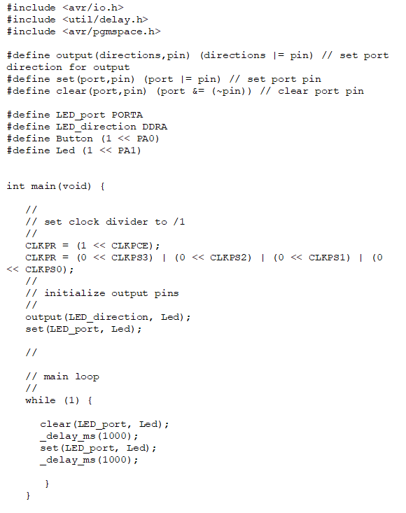
It is now time to program our board from our makefile. We cannot use exactly the same program because we are not in the Arduino IDE. Libraries and functions do not have the same name.I used this week's Hello code to make the following code.
To summarize the code, first it is important to define the ports we will use and the pins. Next, you have to set the registers and in our case it is the register in relation to the clock frequency. After that, you must initialize the pins as in the setup section in our arduino code. Finally there is the main loop of the program which is the same principle as that of the arduino.
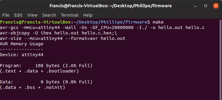
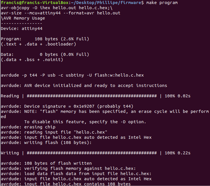
Now it's time to load the program in the board. The first command to use is make because we need to create all the files to laod in the board.
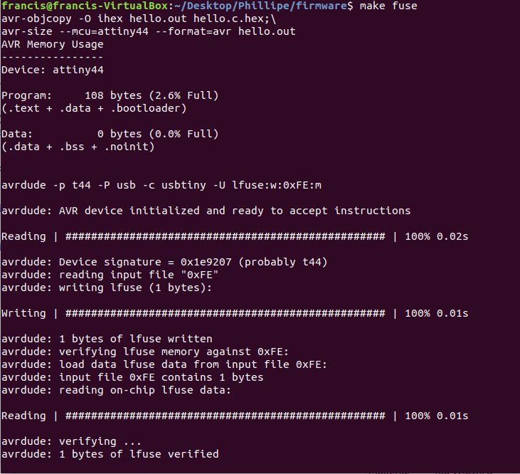
After, we need to use the commad fuse to set all the parameters in the board.
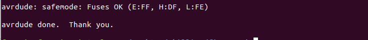
And finally is the command program to laod the program in the board.
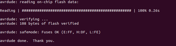
Result
I got the same result as with the Arduino IDE. This is a good thing because my goal was to make a LED flash in two different ways.Group asignement
The person who documents the group assignment this week is Philippe.
You can download all the files of this week right here.