Computer-controlled machining
week 8
March 06, 2019
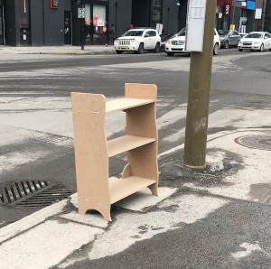
This week, we have to do something big with the CNC. So this week, we have to design our project, choose the right tools for milling, and mill our project. When I heard design something big I asked myself as a question what was the size of this big thing. The CNC which was easily accessible can mill an area of 24x36 inches. Subsequently, I look back the years and noticed that the most popular was to make furniture. I have just moved to a new office and I just miss storage. I decided to make a shelf to put next to my desk.
Make something big with the CNC
Design the 3d model
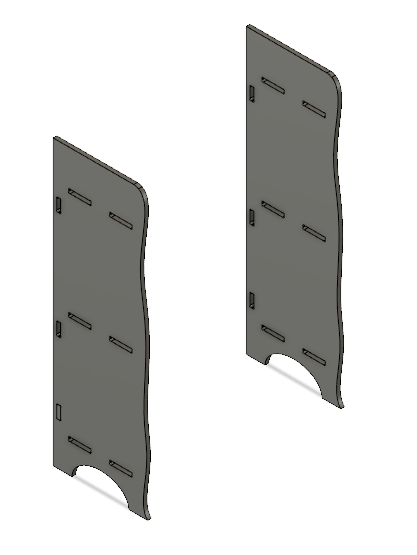
For the design, I wanted to make a shelf that showed it was a custom-made shelf. That's why when I drew the sides, I gave a slightly more special shape than just just two rectangular faces. I decided to make three tablets in my shelf being given that my height was only 36 inches. It is important to put dogbone in all the inner corners of the shape. I explain what is a dogbone in the pressfit test design section below.
I decided to make the shelf pressfit so without using glue or screws. To get more rigidity, I had the suggestion of my Fab manager to put a piece in each corner. This will strengthen the tablets and also prevent the shelf from tipping left and right.This piece will fit in the side panel in the small hole under the tablet and also in the tablet.
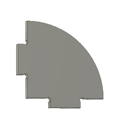
I decided to make two sections that fit into the side of each side to have the most rigidity without weakening the sides.
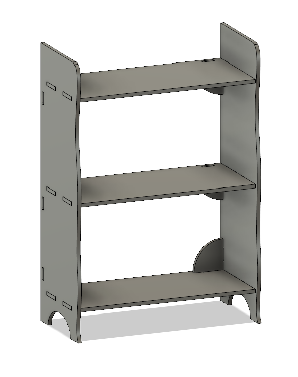
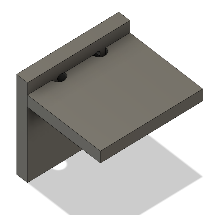
Here is the result assembled with the different components of the drawings. Seen from the front.
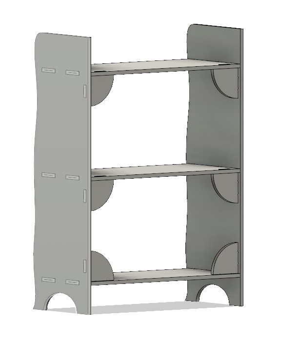
Seen from the back. We can see the parts that helps to strengthen the shelf. The reason that the last two pieces of the bottom are above the shelf instead of below is that it did not have enough space under the last shelf of the bottom.
To be able to make a pressfit part, it is necessary to have the thickness of the material to be able to have a good solidity. I did several tests in the next section.
Design pressfit test
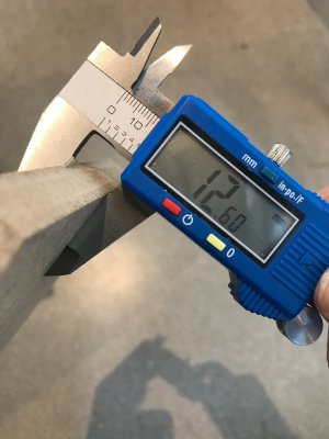
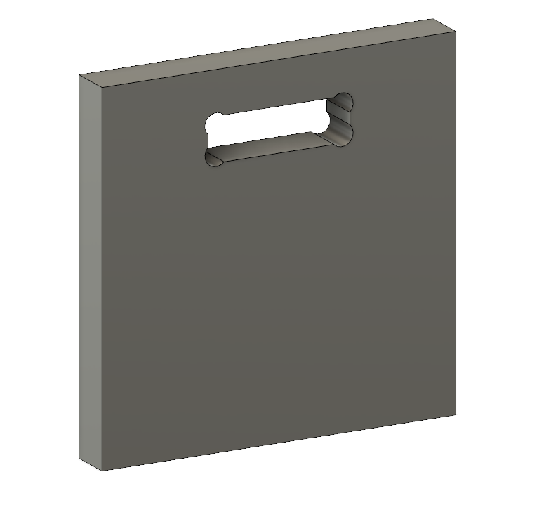
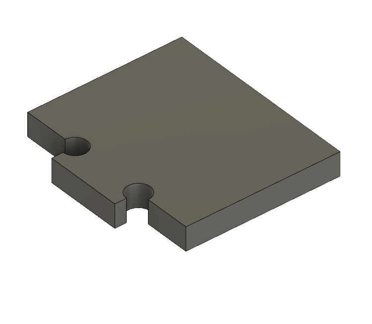
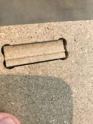
We work with a CNC that has a round tool so it's impossible to make square corners in an inner shape. That's why we need to include dogbones in our design. Dogbones are circles in the inner square corners of a shape. It is not necessary to put dogbone in the outer corners of a shape because the tools can make a square corner outside without problems. I design two pieces that fit into each other to test the good size of a pressfit design. I start with the thickness of the material which is 12.6mm. As seen in the picture below, I put dogbones in each corner of the hole.
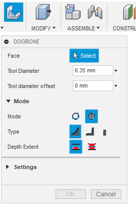
I found an add-in that allows to generate dogbones. The first time I drew my test part I did it manually and I saw that it could take a long time to do if we had more than one. The add-in looks like this and it is very simple to use. It is necessary to enter the diameter of the tools, to select the dogbone type and to choose the face of the component.
To download the add-in click here.
Here is the second part that will fit into the first. Again, you can notice the dogbone in the inner corners of the room so that the piece fits completely into the other
Here are the two pieces insert one into the other.
Design the CAM path
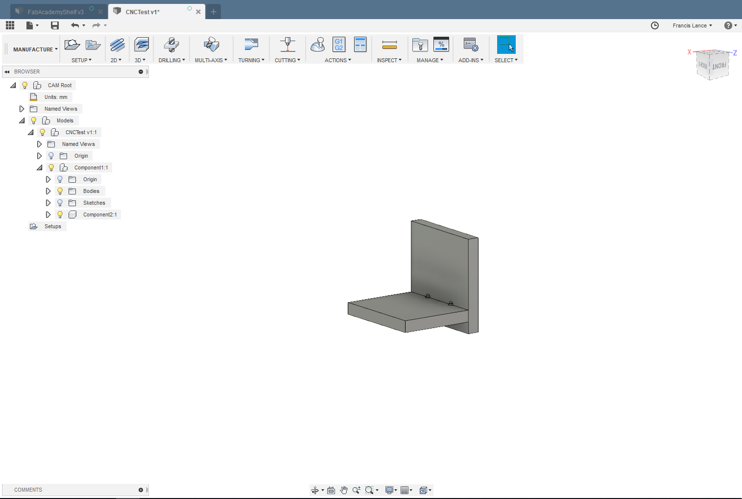
We are now set to make the path for the CNC. For that, I use Fusion360 which has a built-in CAM. In the left tab, go to the manufacture section.
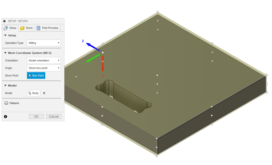
The first steps are to choose the component to print and to make the setup of our path.
The Z axis must always point upwards. In our case we see that this is not the case.
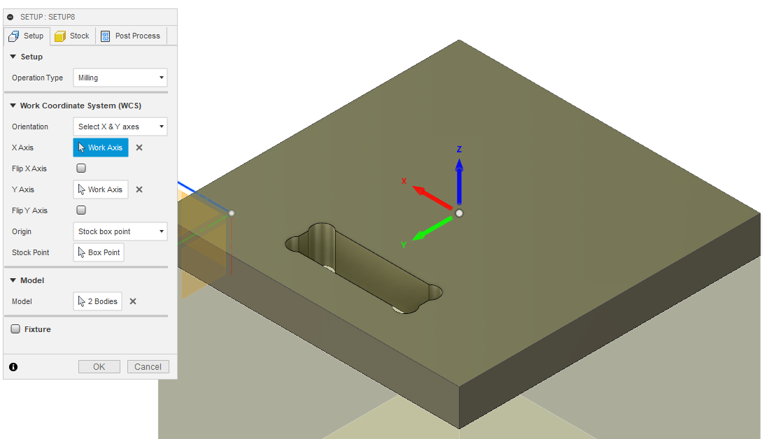
To put our axis upwards, click on select Z axis / plane & X axis in the orientation section. Subsequently, it is necessary to select on the face whose orientation of the Z axis is going to be upwards.
I advise to change the location origin and put it in a corner of the game. For the test, I leave it in the center.
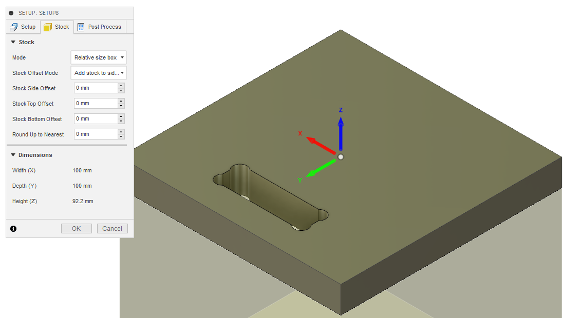
It is possible to put the size of your board that must be cut in the stock tab but I prefer to put the stock to 0 and to position myself the orgine and manage the material manually on the CNC.
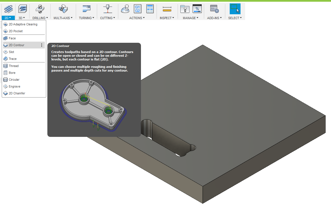
The component is achievable with a 2D cut as it is a 2D image with a thickness. For the type of path according to the description that the software gives I decided to choose the 2D outline. With this type of cut the tools will follow the outside line of our component.
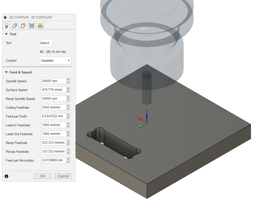
For this section, I selected a 6.35mm (1/4 inch) tool to cut my part test into the MDF board. I also put the speed spindle at 24 000 rpm, cutting feedrate 2500 mm/min and leave the other parameters suggested by the software according to the chosen tool. the speeds are the advises of my mentor.
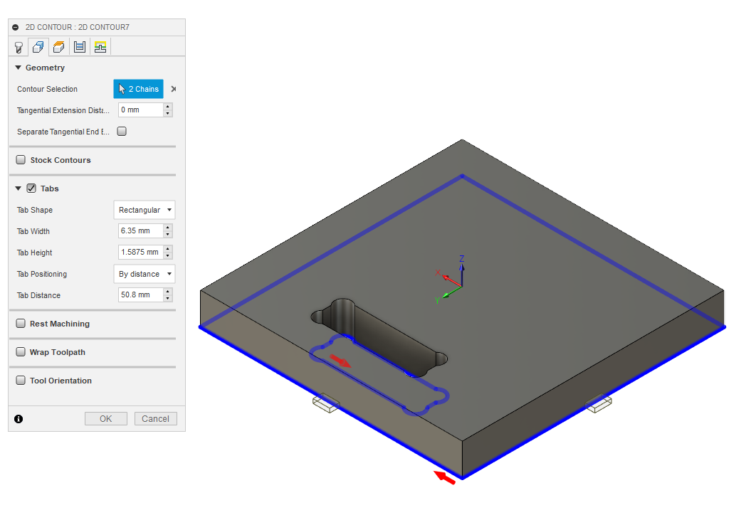
In the geometry section, I selected the two cut lines of my part. An important thing here is to put tabs. Tabs are small parts of our part that are not cut off voluntarily to keep it in place during the cut. Here I selected the rectangular tabs with a width identical to the cutting tools. Also I chose to put the tabs every 50 mm to have some after the part.
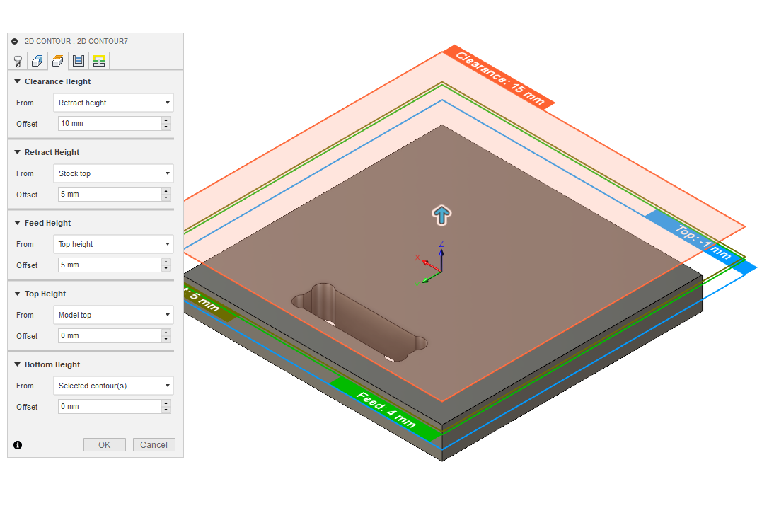
In the clearence section, I only selected the top height as the model top because I did not cut any material on the top of the component. So all height distance starts on top of the part.
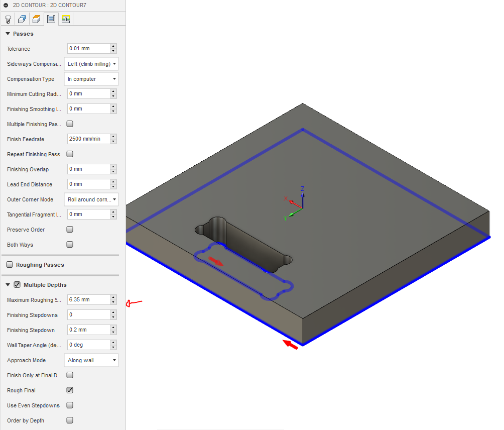
In the section passes, I have selected to make the cut in multiple passes to not go too hollow in matter. Generally, the depth of the cut corresponds to the diameter of the tools. So I put the depth to 6.35 mm (1/4 inch).
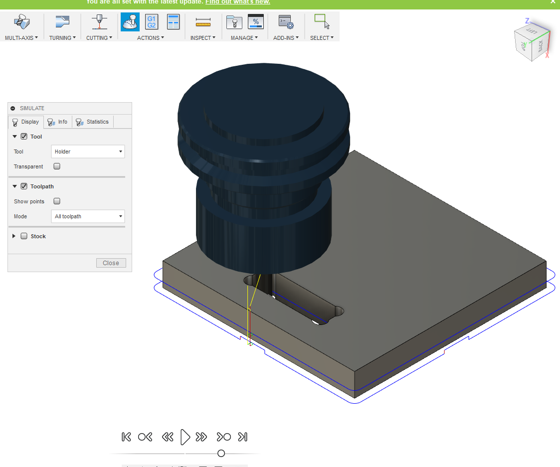
To check the path, I suggest releasing the built-in simulation in Fusion 360 to make sure the tool moves as expected.
Milling parts test
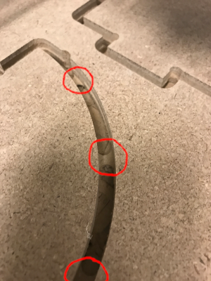
I milled the two parts and what I want to show in the photos are the tabs.I put these in to hold the part in place.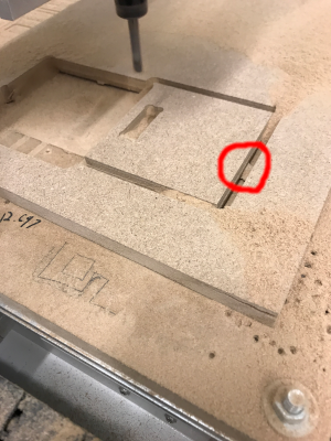
Test result
My first dogbone really looked like a dog bone. I made a circle with a diameter of the size of the tool centered on each corner of my rectangle.The height of the hole is the thickness of the board which is 12.6 mm.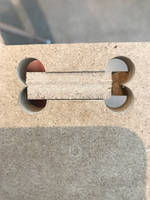
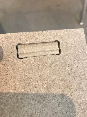
After that, I redid the same room but using the add-in mentioned above to do the dogbones. I made it with the same thickness as the previous one (12.6 mm)
I did another 12.5 mm and we can see the distance between the two parts is smaller
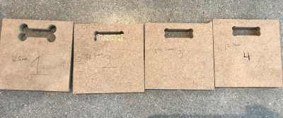
In this picture, you see my 4 test. In order the tickness is 12.6 mm - 12.6 mm - 12.5 mm - 12.2 mm. At 12.2 mm the pressfit was almost perfect so I decided to put the thickness of my final project at 12.1 mm.
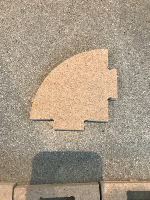
Here is the first milled piece to test the pressfit that is in my original design.
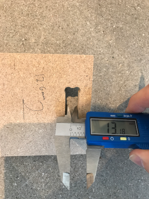
I found it strange to have to go down to 12.1 mm when the actual thickness was 12.6 mm. So I decided to measure the milled parts. We can see on the piece of 12.6 mm is really 13.18 mm. the difference is 0.58 mm.
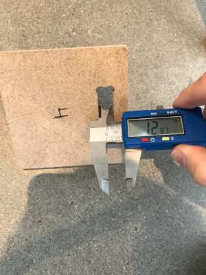
The 12.2 mm piece is actually 12.87 mm. We can see that 0.67 mm. So we must consider that our CNC with the tools of 6.35 mm can have a difference of 0.67 mm on our actual measurement.
Milling my design
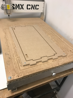
When milling, it is important to wear a mask and safety glasses. I also followed the tools with a vacuum cleaner to reduce the amount of dust in the air. I also fix the board with screws so that it does not move when milling.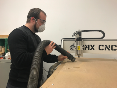
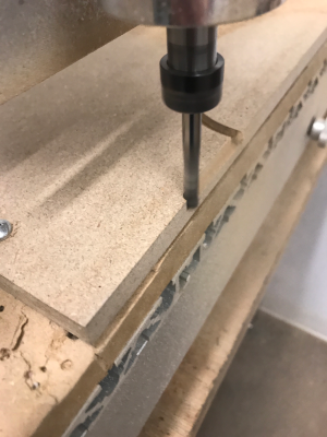
My biggest part was the sides. It measured 35.5 inches high and the milling machine can be 36 inches. It was very tight but by moving the origin of a few millimeters at a time I was able to find a way to cut my board.
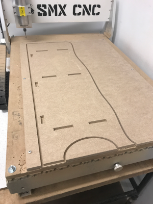
Here is a picture of my side during the milling to show that I was at the limit of the milling machine.
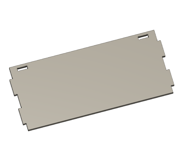
Here is the first tablet out of three that has been milled. We can better see in this photo the screws used to hold the board in place during milling.
Assembling my design
Now is the time to assemble all parts. Here is a view of all the pieces of my design before assembly.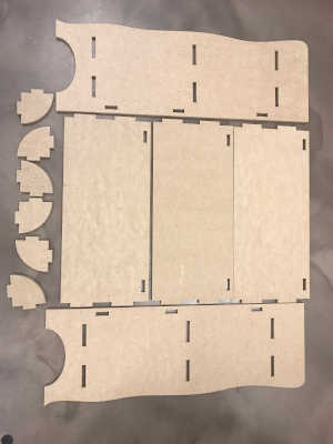
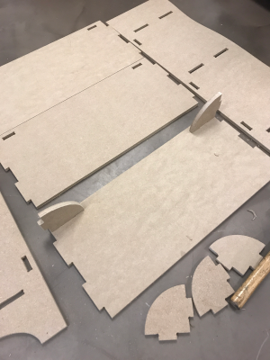
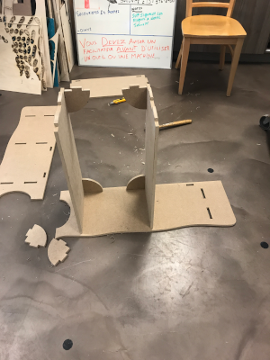
I started assembling both part which serves to give rigidity to the tablet. It is more simple to put them before inserting the tablet into the side.
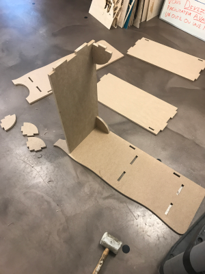
After thar, I inserted the tablet in the side. I needed to hit the tablet with a rubber hammer to insert it. I suggest a rubber hammer because it reduces the risk of damaging the parts.
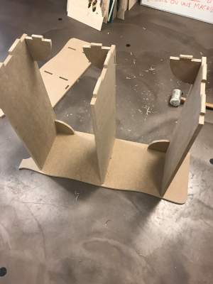
I repeat the same steps for the second tablet.
Surprise, I repeat the same steps for the third tablet.
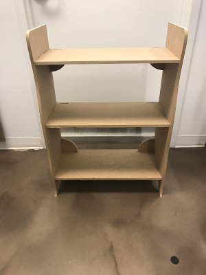
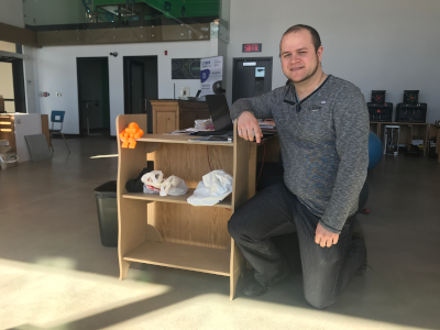
I finished assembling the second side and that was the last piece. Here is the final result.
Group asignement
The person who documents the group assignment this week is Sylvain Brunet.Hero shot
You can download all the files of this week right here.