Output device
Introduction
This week our assignment was to:
• individual assignment:
add an output device to a microcontroller board you've designed,
and program it to do something
• group assignment:
measure the power consumption of an output device
I was waiting for this week, as during this week I will test my board.
During this week I will use the board of my final project, I described it in
Week9
As a reminder I will write about my final project.
The final project is about shutter blinds automation.
In the framework of the project I am going to use
the following components
• Dc motor Jameco 253471
• Motor driver A4953
• Atmega 328 P microcontroller
• Switches
• Light sensor
• Resistors, capacitors etc.
During this week we should control output device (DC Motor)
Step 1 - Figuring out what is motor driver and motor controller
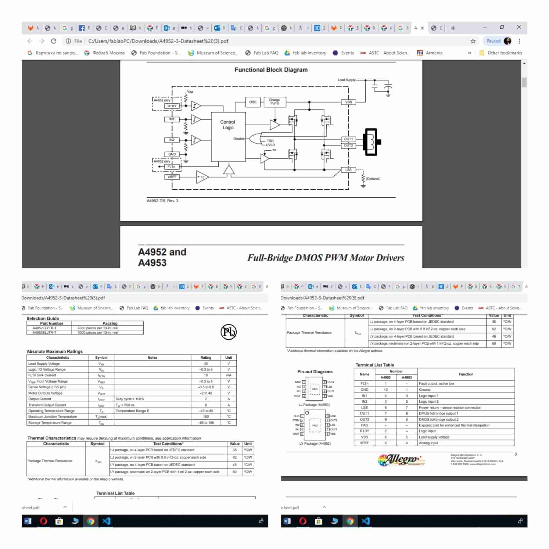
I found an interesting video about the differencies of motor drivers and motor controlers H-bridge (motordrver) is the most common way to drive a brushed DC motor, and its operation is quite simple. It uses two pairs of transistors (usually MOSFETS) to control the direction that current is allowed to flow through the motor. By changing the direction of the current flow (reversing the voltage across the terminals), the direction of rotation will change. the idea of a motor controller is that you can just wire up your motor and power supply, drop the controller into an existing p roject, and communicate with it as easily as the protocol allows for. Digital communication with a motor controller even allows for feedback data such as current measurement and error detection. Motor controllers with USB support allow you to control a motor directly from a USB host such as a computer! The software/protocol will depend on the board itself with each brand being different, but it's pretty cool. So all you need to control a motor driver is a device which can communicate with it via the methods that are supported by the controller board.As I mentioned below I am going to use A4953 motor driver. Here you can download the datasheet of the driver.
Designed for pulse width modulated (PWM) control of DC motors, the A4952 and A4953 are capable of peak output currents to ±2 A and operating voltages to 40 V. Input terminals are provided for use in controlling the speed and direction of a DC motor with externally applied PWM control signals. Internal synchronous rectification control circuitry is provided to lower power dissipation during PWM operation. Internal circuit protection includes overcurrent protection, motor lead short to ground or supply, thermal shutdown with hysteresis, undervoltage monitoring of VBB, and crossovercurrent protection. The A4952 is provided in a low-profile 10-pin MSOP package (suffix LY) and the A4953 is provided in a low-profile 8-pin SOICN package (suffix LJ). Both packages have an exposed thermal pad, and are lead (Pb) free, with 100% matte tin leadframe plating.
Step 2 - Start making the board
I have developed this board for my final project, used Kicad software for the drawing.
Here you can see my svg files
• Interior
Front layer(1_64 inch end mill).svg)
• Cut out
Holes(1_32inch holes,and cutout).svg)
Starting cutting process by SRM-20 milling machine.
Setting up the machine
• Turn on the machine
• Put the material in the machine, fixed it with double sided stick
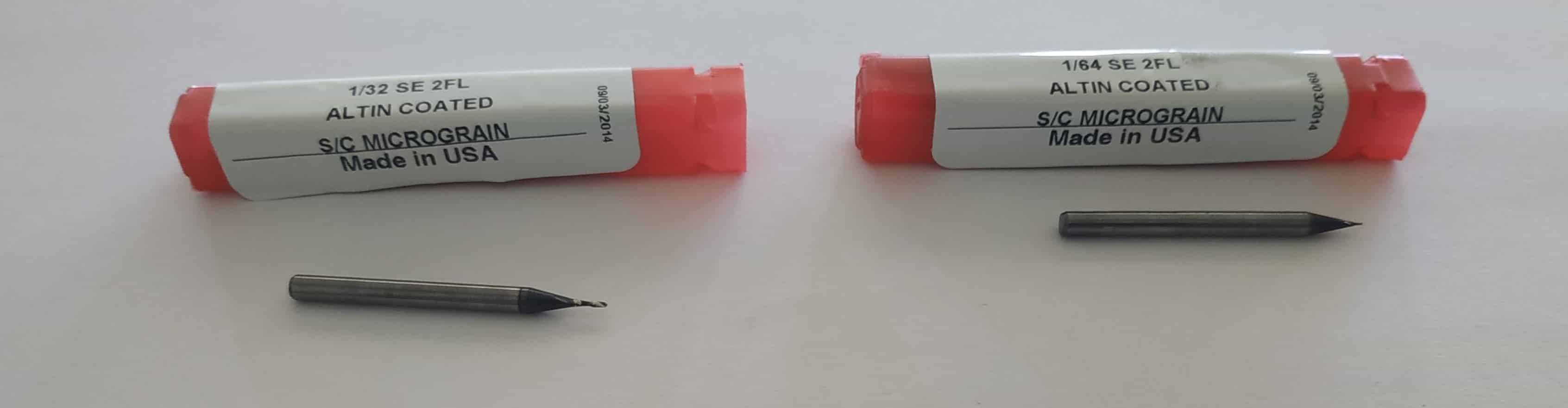
• Attached end mill 1/64 for milling traces
• Opened fab modules and upload my files there, then saved
• Setted the origin point chose"[Machine Coordinate System" in our case I will use "G54" and "G55" that's the first 2 of 6 Work Coordinate Systems. During this process I used Vpanel pointers "right" "left" "up" "down"
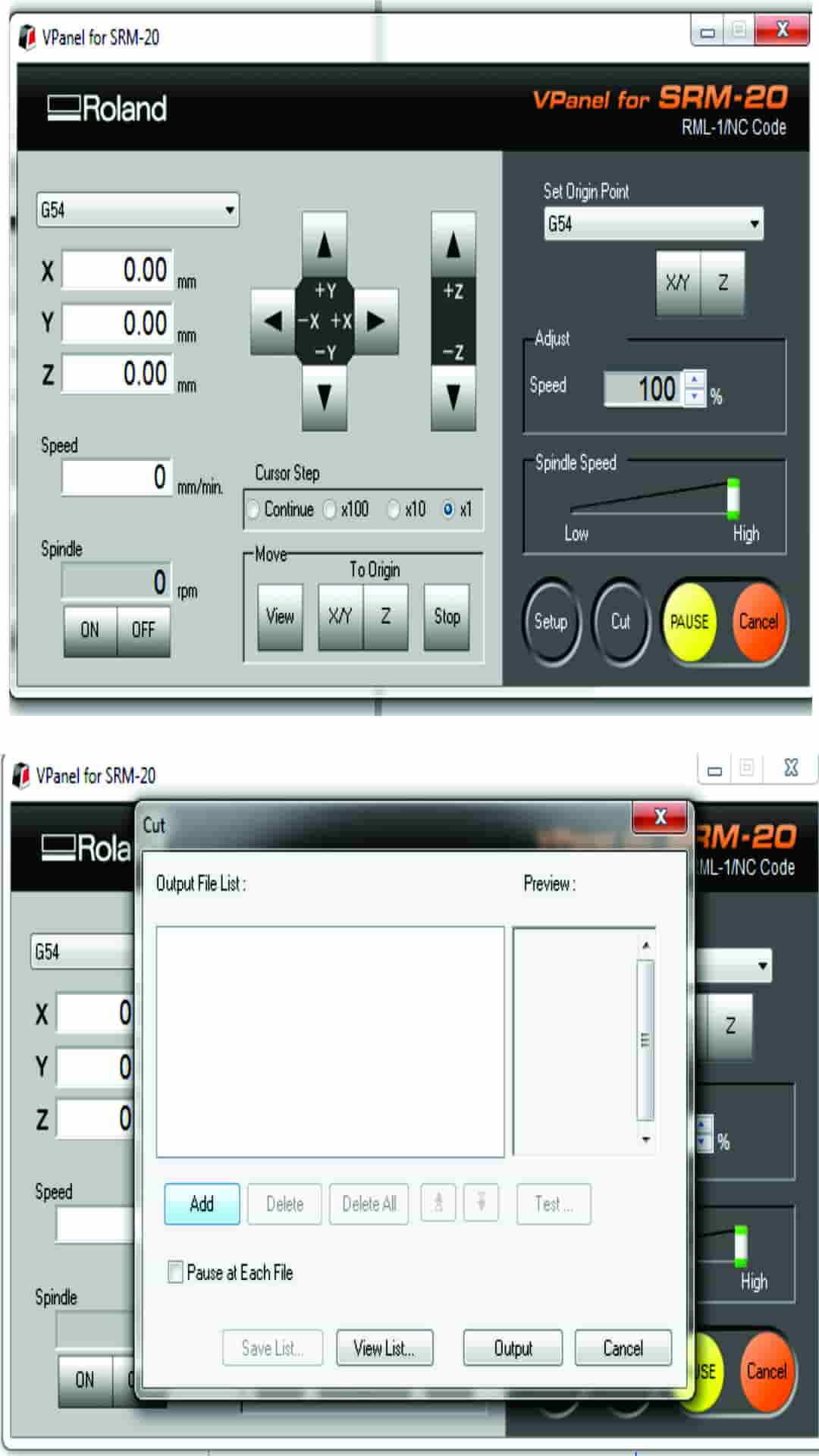
• Went back to fab modules and chose image "png"- Gcode "nc"-PCB traces "1/64" - "selected calculate" - "save".
When the files had been saved I sent them to machine for cutting. Started the cutting process and paused to check how it was going on. For cutting out the boards I opened fab modules chose image "png"- Gcode "nc"-PCB interior "1/32" - "selected calculate" - "save". Then I cleaned the board and started soldering process.
Here you can find my G code files.
After the cutting I washed my board and start soldering of components.
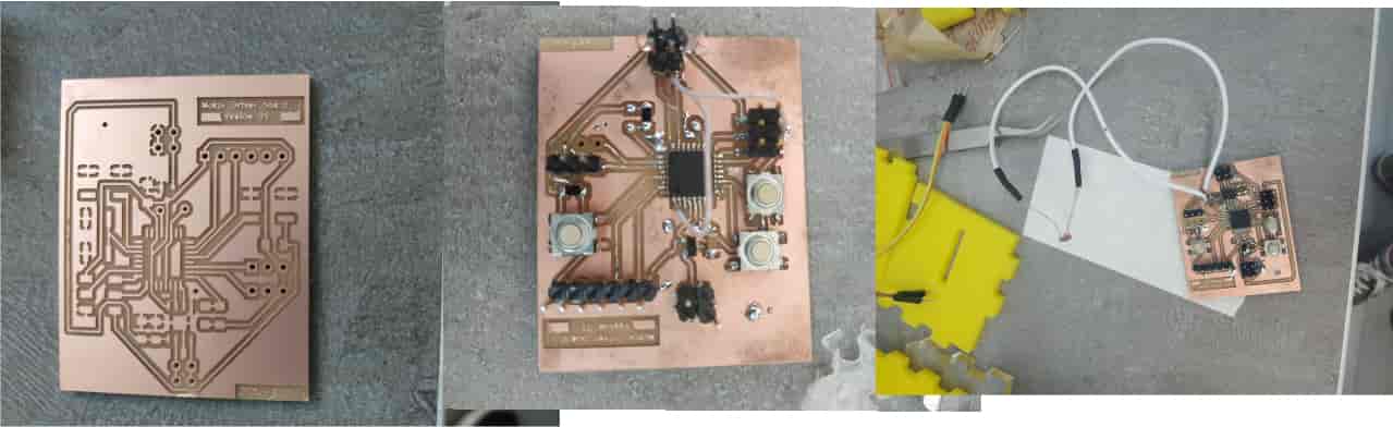 I decided to cut my board again, as I demaged the previouse one.

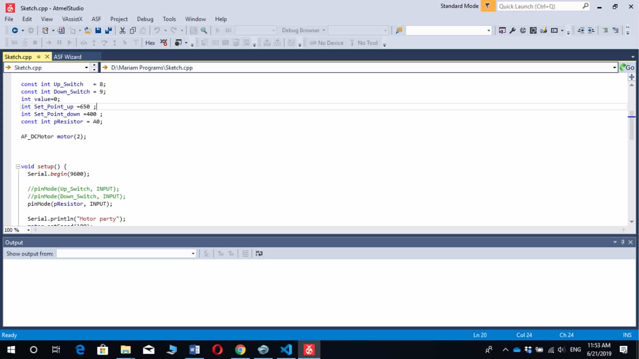
After I started the programming. I used atmel-studio-7 for programming my microcontroller. I tried to write the program many times, when I finished I started trying program my board by AVR programmer. After it programmed from the first time, but had problems with programming. I reprogrammed the the board for many times untill got the necessary result. But the problem was in board the motor driver was demaged. If the light sensor send comman thet sunlight is strong the motor started work and scroll down the shutter and stop by pressing switch, shutter blind goes up if the it is dark and stop by getting the switch.
"const int Up_Switch = 8;
const int Down_Switch = 9;
int value=0;
int Set_Point_up =650 ;
int Set_Point_down =400 ;
const int pResistor = A0;"
AF_DCMotor motor(2);
Finally my driver and the board worked. You can download the program from here.
More information about the programming is available at Week 9 page
Files to download
• Board• Project
• Schematic The results you can see here
During this week I improved my skills on poragramming and tested the motor driver for my final project.