
Output devices --- Ելքային սարքեր
Introduction --- Ներածություն
For this week we had to:
Add an output device to a microcontroller board you've designed,
and program it to do something (individual assignment)
measure the power consumption of an output device (group assignment)
I decided to use Neil's echo.44 PCBs and concentrate more on learning how to use different
devices.
I've made PCBs and tested with:
LCD display
Bipolar stepper motors
Making of the PCBs --- Տպատախտակի պատրաստում
I've added names of the output devices on the PCBs. In order to see how I added the names go
to
my week11.
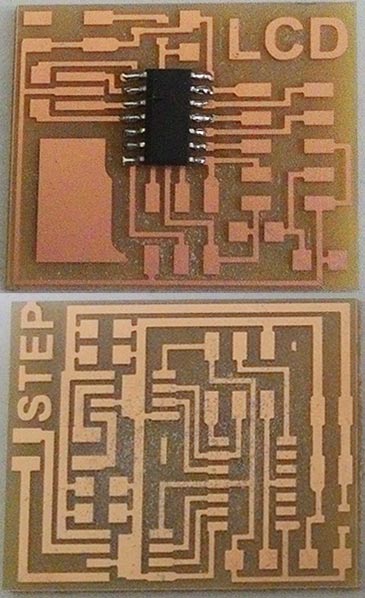
Here are the echo.44 boards with the names added:
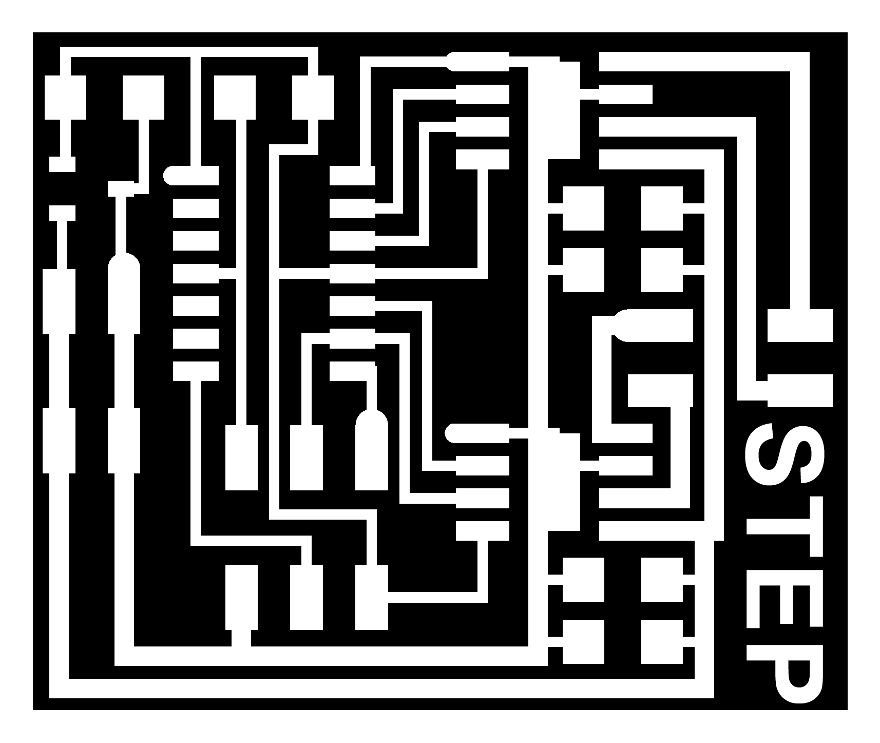
hello.stepper.bipolar.44 traces, and it's interior
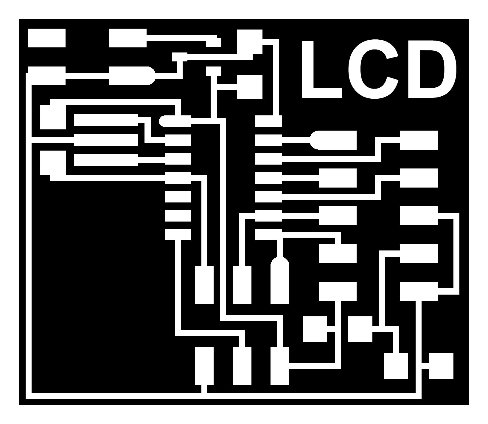
hello.LCD.44 traces, and
it's interior
To make the milling process easy I combined the files with Adobe Photoshop. I used Fabmodules to generate the toolpaths. To learn how to use Fabmodules you can check this tutorial. I changed the "number of offsets" value from 4 to 7 to have less extra copper around the traces. That makes soldering process easier.
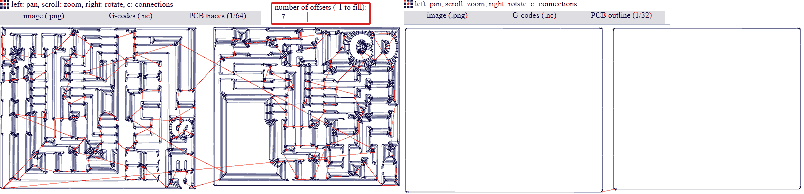
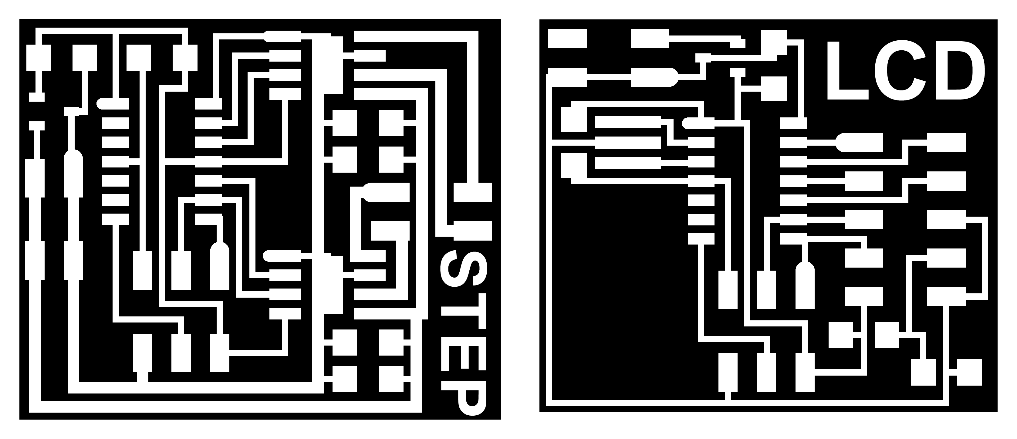
Here are the echo.44 (LCD, Bipolar stepper) boards in one file:
hello.stepper.bipolar&LCD.joined.44.traces,
and it's interior
COMBINED
Soldering the components --- Բաղադրամասերի զոդում
You can find the component list in Neil's keynotes for Output devices but I will post them here too.
For LCD board you need
1xATtiny
44a
1x1k SMD 1206 Resistor
1x10k SMD 1206 Resistor
1x100k SMD 1206 Resistor
1x1uF SMD 1206 Capacitor
1x20MHz Resonator
1x5v Linear
Voltage Regulator
1x 2x5 male pin headers (For LCD)
1x 2x5 female connector (For LCD)
1x 2x3 male pin headers (For ISP)
1x 2x2 male pin headers (For Power)
Ribbon cable of 10wires (For LCD)
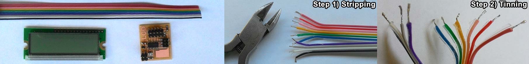
LCD display
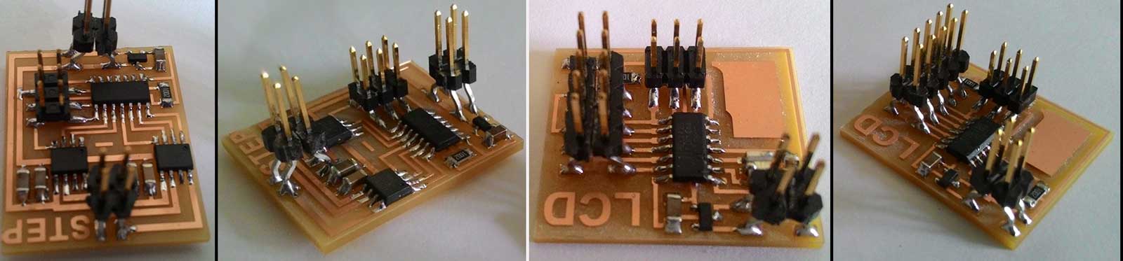
Here are the ready PCBs
For bipolar stepper motor board you need
1xATtiny
44a
1x10k SMD 1206 Resistor
2x0.1uF SMD 1206 Capacitor
1x1uF SMD 1206 Capacitor
2x10uF SMD 1206 Capacitor
2x A4953
Full Bridge motor drivers
1x5v Linear
Voltage Regulator
1x 2x3 male pin headers (For ISP)
2x 2x2 male pin headers (1xFor Power and 1xFor motor pins)
In order to connect LCD display to the board we need to solder the Ribbon cable to the LCD display ports and attach the female connector to the other end of the cable. Take the ribbon cable spool and cut at least 5cm of it. Then Strip the edges on one side of the cable. Then tin the wires that were striped. More about tinning ad why do we need that you can find here Tinning Stranded Electrical Wire
Then take the LCD display flip it and put the 4 wires into the first 4 pin holes so that they will stick out from the backside of the LCD display. Then solder them as shown in the image below. Do theat with the rest of the cables see the image below.
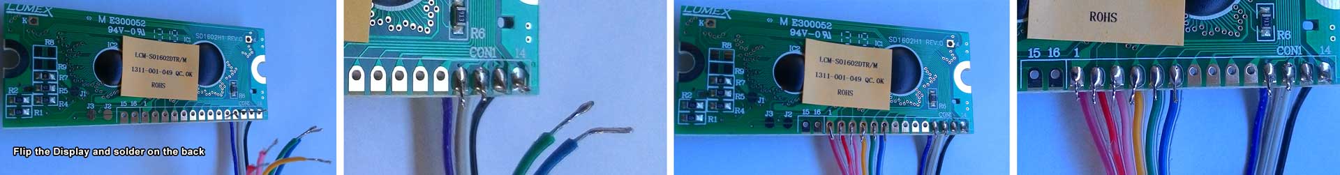
Here is the LCD with soldered ribbon cable and it's connector installed. I numbered the pins in the image to help identify where you should put each wire.
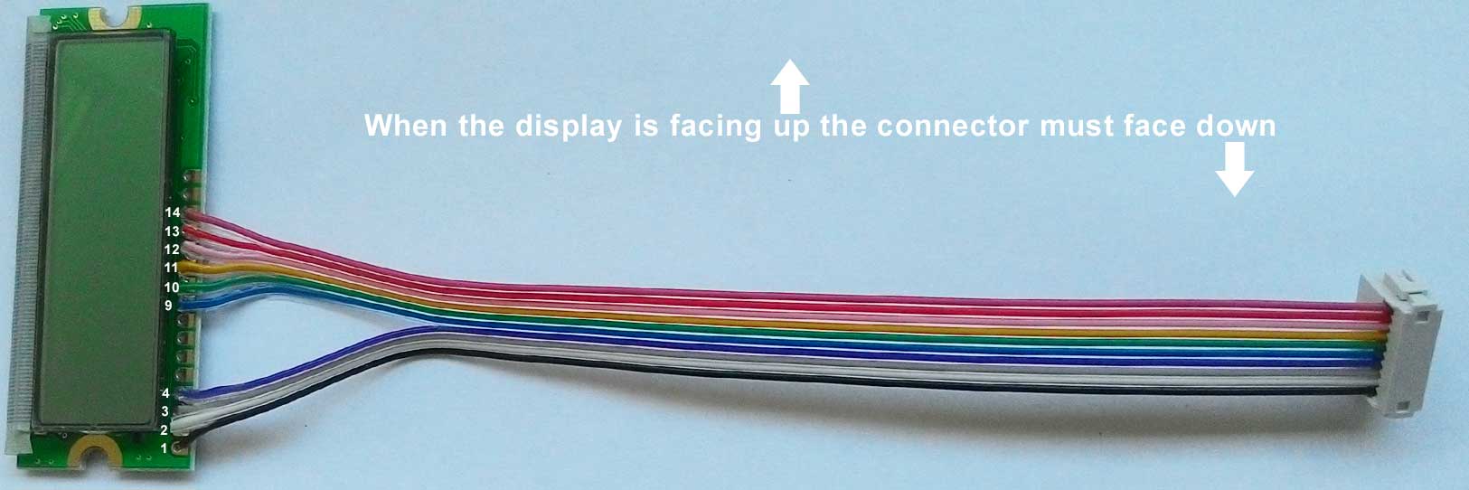
Finnaly press the 2x5 female connector as shown in the imge above. When the display is facing up the connector must face down.
Programming --- Ծրագրավորում
I used Ubuntu and FabISP we made on week5 to program the boards. In order to program this boards we will need the C codes, libraries and makefiles from the Output week keynotes for each board separately. My advice is to keep them in separate folders and name them accordingly.
Liquid Crystal Display Board --- Հեղուկ բյուրեղյա ցուցասարքի ղեկավարման սպատախտակը
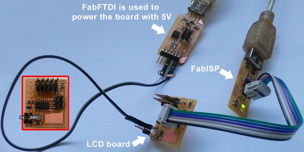
Connect your usbtiny (FabISP) to the LCD board's ISP port using the ISP cable, connect 5v and GND to your LCD board's power input pins as shown in the image below and finnaly connect FabISP to the USB port of the computer
For programming the LCD board you will need
- An Ubuntu computer with "avrdude" and "avr-gcc" installed (Need to install? go HERE)
- FabISP
- ISP cable
- 5v power source (FabFTDI or FTDI cable will work)
- C code
- LCD library
- makefile
- (Here are all the LCD files in one place.
Unzip this and you'll get an "LCD" folder)
Type this command and hit enter:
make -f hello.LCD.44.make program-usbtiny
-f scecifies the makefile's name in this case it's "hello.LCD.44.make"
program- specifies the programmer we're going to use in our case "usbtiny"
(!!! if you use other programmer change "usbtiny" to "avrisp2" or "dragon_isp" !!!).
Overall this command makes the .hex file based on the library and the C code.
If everything goes right you should see this message
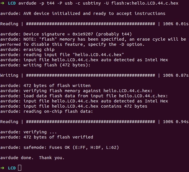
Next type this command and hit enter
avrdude -p t44 -P usb -c usbtiny -U flash:w:hello.LCD.44.c.hex
-p scecifies the AVR device in our case t44 (ATtiny44)
-P specifies the connection port in our case USB port (FabISP)
-c specifies the programmer type in our case it's usbtiny
(!!! if you use other programmer change "usbtiny" to "avrisp2" or "dragon_isp" !!!).
-U specifies a memory operation (multiple options available)
in our case "flash" flashes the ROM, "w" reads the .hex file and writes it to the memory.
If everything goes right you should see this message. Congradulations you're done!.
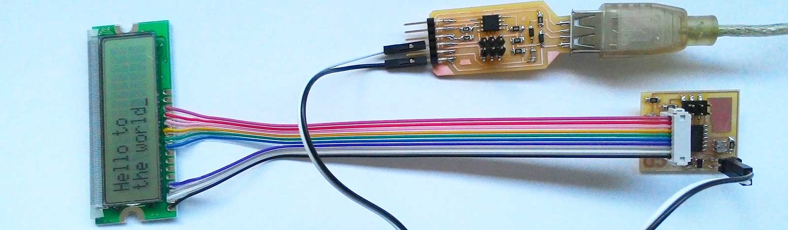
Now disconnect ISP cable from the LCD board and connect the LCD display with the 2x5 connector to the board as shown in the image below.
Now go ahead and change the C code to write something else.
Bipolar stepper motor Board --- Երկբևեռ քայլային շարժիչի ղեկավարման տպատախտակը
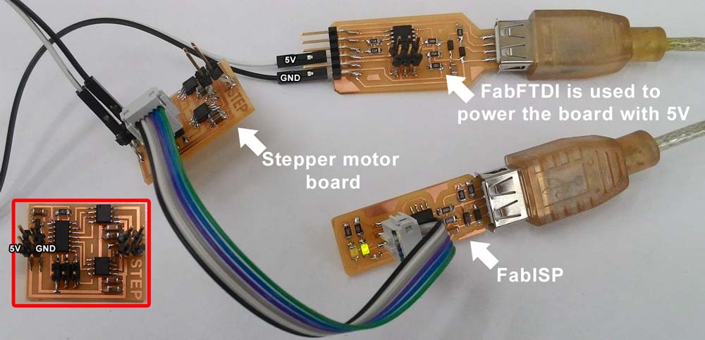
Connect your usbtiny (FabISP) to the Bipolar stepper motor board's ISP port using the ISP cable, connect 5v and GND to your Stepper motor board's power input pins as shown in the image below and finnaly connect FabISP to the USB port of the computer
For programming the Bipolar stepper motor board you will need
- An Ubuntu computer with "avrdude" and "avr-gcc" installed (Need to install? go HERE)
- FabISP
- ISP cable
- 5v power source (FabFTDI or FTDI cable will work)
- C code
- makefile
- (Here are all the Bipolar stepper
files in one place.
Unzip this and you'll get an "Bipolar stepper" folder)
Type this command and hit enter:
make -f hello.stepper.bipolar.44.full.make program-usbtiny
-f scecifies the makefile's name in this case it's "hello.stepper.bipolar.44.full.make"
program- specifies the programmer we're going to use in our case "usbtiny"
(!!! if you use other programmer change "usbtiny" to "avrisp2" or "dragon_isp" !!!).
Overall this command makes the .hex file based on the library and the C code.
If everything goes right you should see this message
Next type this command and hit enter
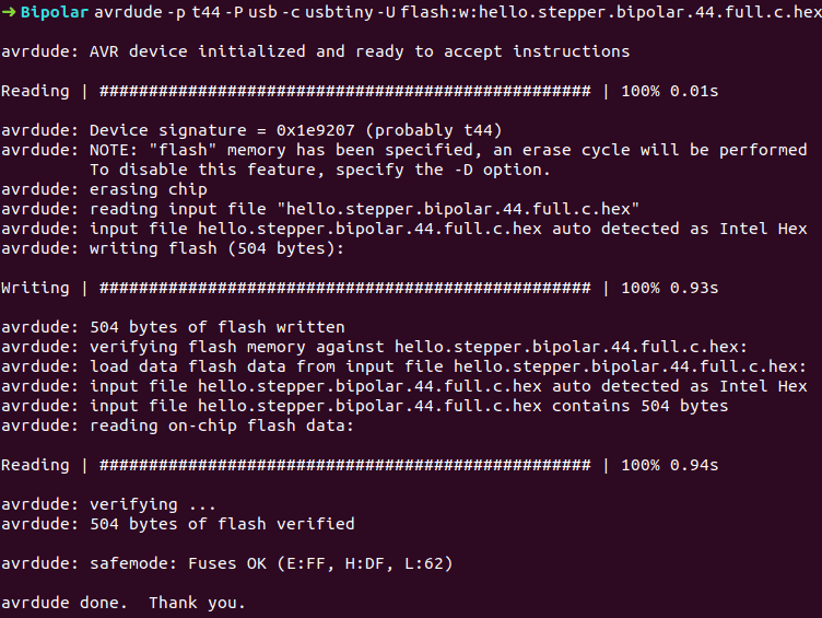
avrdude -p t44 -P usb -c usbtiny -U flash:w:hello.stepper.bipolar.44.full.c.hex
-p scecifies the AVR device in our case t44 (ATtiny44)
-P specifies the connection port in our case USB port (FabISP)
-c specifies the programmer type in our case it's usbtiny
(!!! if you use other programmer change "usbtiny" to "avrisp2" or "dragon_isp" !!!).
-U specifies a memory operation (multiple options available)
in our case "flash" flashes the ROM, "w" reads the .hex file and writes it to the memory.
If everything goes right you should see this message. Congradulations you're done!.
Now disconnect ISP cable from the Bipolar stepper board and connect it to a bipolar stepper motor (it must have 4 wires). Some years ago I disassembled an old scanner and a floppy drive and those motors were stepper. So I tried to figure out the wire colors for those steppers. I couldn't find a referance for my motors in internet, so I desperately began to try randomly and enentually found a clue.
Useful links
Avrdude option descriptions
Avrdude help
Tarek Asfour week11