
Computer-Controlled Machining.
For the assignment of the 8th week: Computer-Controlled Machining, it will be divided into 6 differentiated parts: Design, Fabrication, Assembly, Problems, download files and group assignment. The goal of this week it is create something BIG.
Desing
My idea for this week is to create a shelf that can be scaled to have different levels, ideal to take advantage of some free space you have at home.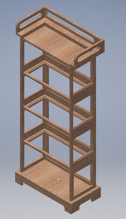 This design can be parametric without major problems, however, since it is a piece of furniture that I will use in my home, I have the exact measurements and I digit them directly without designing in a parametric way.
It will be divided into three main parts:
- Base Here will be the legs of the shelf.
- The body This area can be increased depending on the space needed
- The final part It will have some small ornaments where you can hold in case you want to move without disarming it
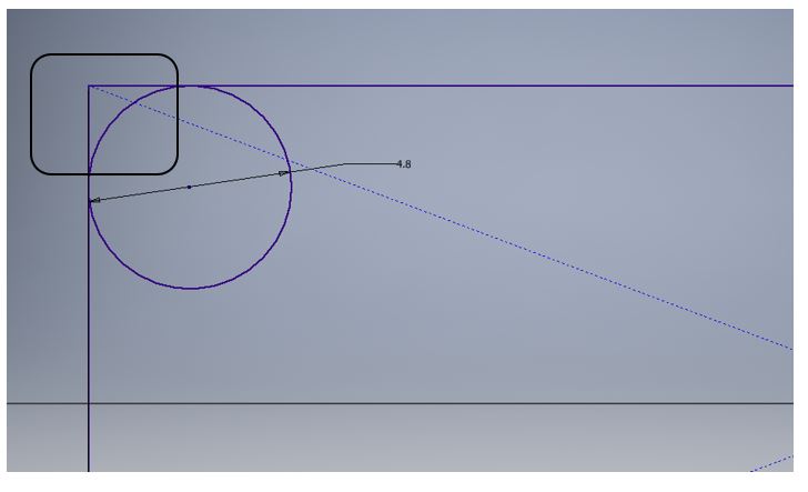 For this reason and knowing that the diameter of the tool is 3/16 "that would be about 4.8mm, the following design is made in the corners:
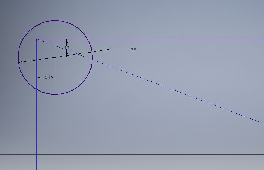 A circle is drawn at a distance r / 2 from the corner, the radius of the tool being used, so we make sure that the desired corner can exist.
It is about not having a greater distance to avoid having very deformed shapes in our design.
A circle is drawn at a distance r / 2 from the corner, the radius of the tool being used, so we make sure that the desired corner can exist.
It is about not having a greater distance to avoid having very deformed shapes in our design.
Base
The base consists of a table as a base and the front and side legs, as shown in the picture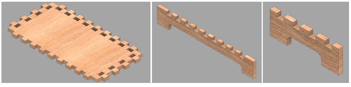
Central
For the central part, which is the modular zone, it is composed of 4 parts: left side, right side, base and back side, as you can see in the picture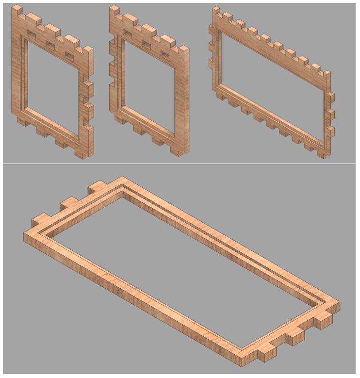
Final
For the final zone, two pieces of the central zone and additional pieces are used, as shown in the figure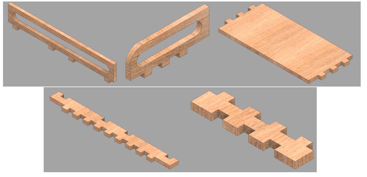 Below you can see a small animation of how the final assembly of our design will be with all his parts, in this case with 4 leves.
The material used is plywood is 18mm, after some tests carried out in group work, which will be seen later, this material does not need a tolerance in the inserts, as was done with the cardboard in the laser cutter.
Fabrication
The machine
In the lab, we use the CNC Multicam 3000. This machine is a CNC router that allows making 2D cuts in wood, plywood, MDF and other raw materials to perform, generally, carpentry work.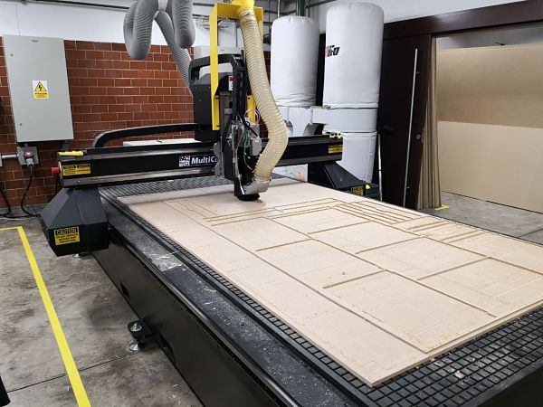 (multicam)
The maximum working dimensions can be seen in the following picture.
(multicam)
The maximum working dimensions can be seen in the following picture.
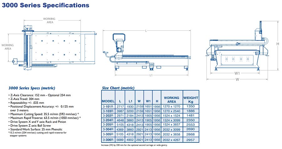
Source: https://www.multicam.com/3000-series-cnc-router/
An important characteristic of the Multicam is the vacuum that is produced in the work area, this is done to avoid that the material being cut does not move. However, in some occasions it is necessary to screw the material into an additional wood and in this way make sure that the material will not move.You can read more about the machine here (https://www.multicam.com/3000-series-cnc-router/)
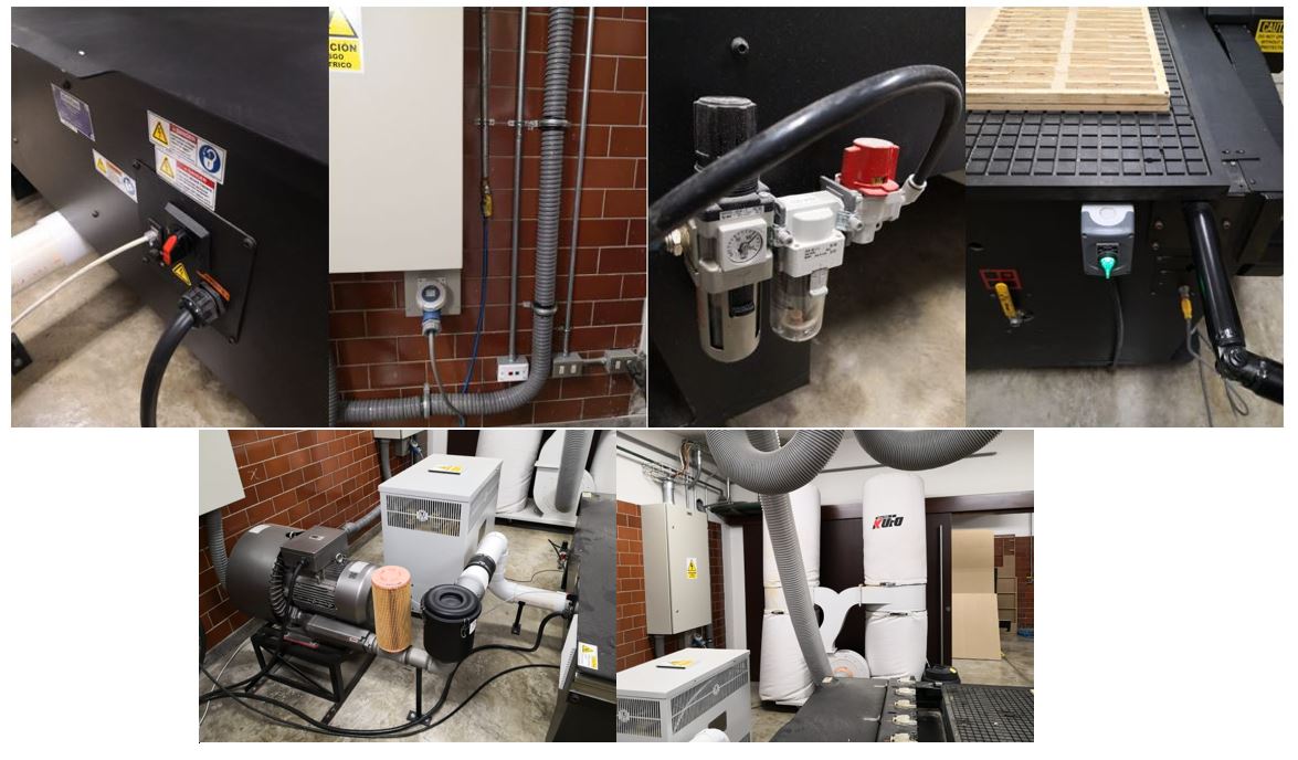
Security protection: Personal Protection Equipment (PPE)
When working with wood, it is very important to work with the necessary safety elements to avoid accidents during work and in the long term. Many of the particles that are suspended in the air can be carcinogenic, so it is necessary to wear lenses, gloves, respirators,earmuffs, work clothes, safety boots and to be in the safety zone while the machine is in operation, this area we have it delimited by a yellow line on the ground.
Source: http://www.abodana.com/personal-protective-equipment-market/
Test the machine
A good way to make an optimal design, is to know the limitations and operation of the machines, in this case I made some designs for its cutting and testing.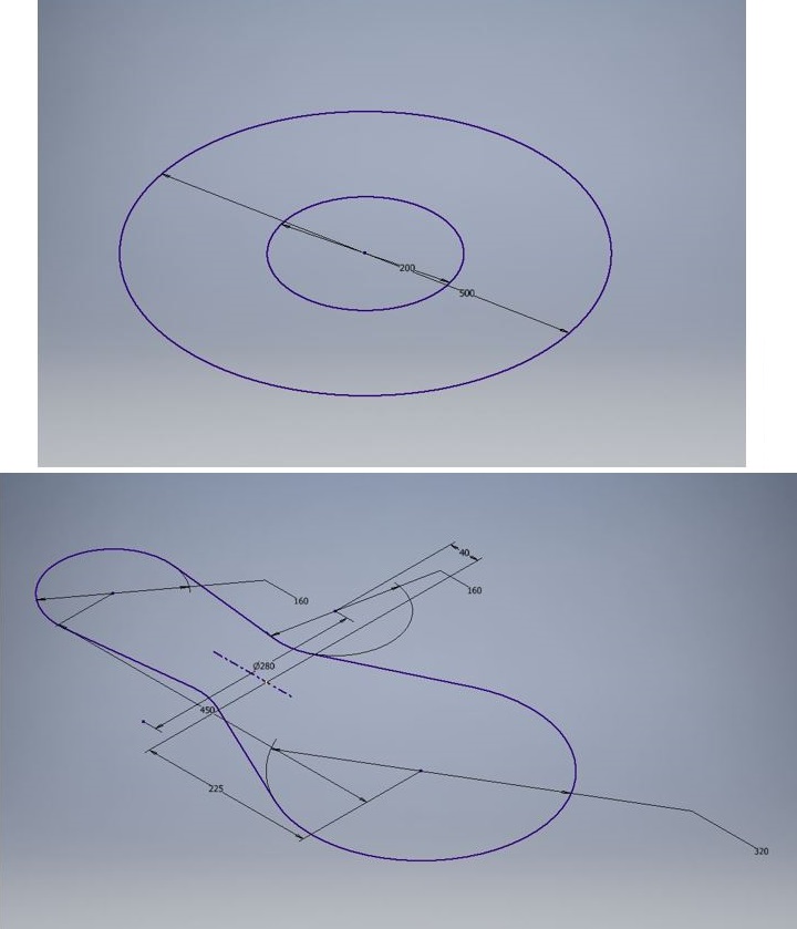 The design consists of a pair of concentric circles of 200 and 500mm diameter and then a more complex design with circumferences and tangencies.
The tools that are used are the 3/16 "and 1/2" endmill. The material used is plywood because it is a resistant and quite economical material. For this task they recommended us to use it because it is the most abundant material available in the laboratory.
After the cuts we have the following results.
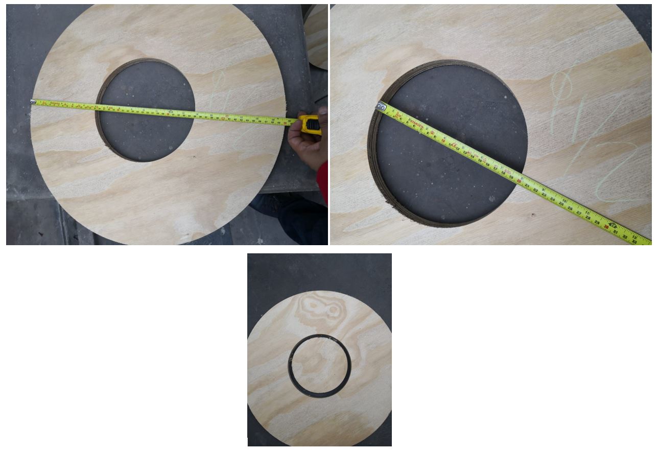 With the 1/2" milling cutter we have an external circumference of 50cm while the internal one measures 19.9mm
 In the case of the milling of 3/16" we obtain the same results in the exterior, but in the inner circle if we have 20cm of the design.
After this results I will use the milling of 3/16" when obtaining such favorable results.
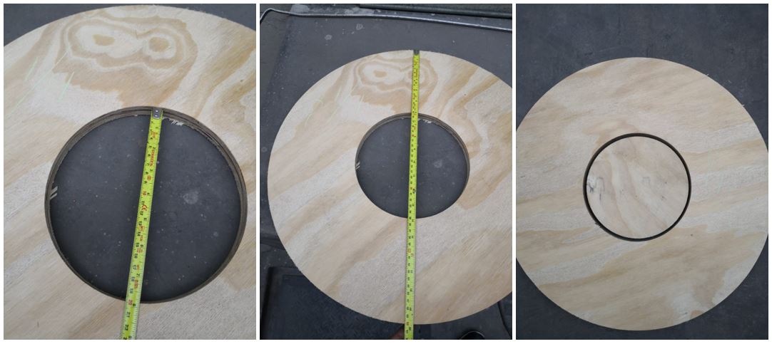
 In this design we have the same results when only making an exterior cut.
Export files
The software that uses the Multicam (enroute cad cam) only recognizes files of the DWG type, for it we must export each face of all the pieces, to carry out this process in a faster way by means of the Inventor software (software that I used for the design ), we right click on the face of the cut and select export with the DWG format, as shown in the picture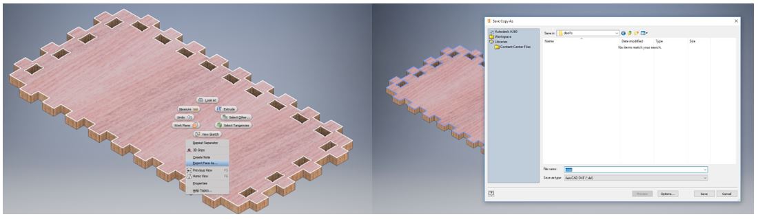 Once all the parts have been exported, we use the AUTOCAD software to place the pieces manually with the help of the technicians and the experience they have with the Multicam, the minimum space that must exist between the parts is 20mm. The result is as follows.
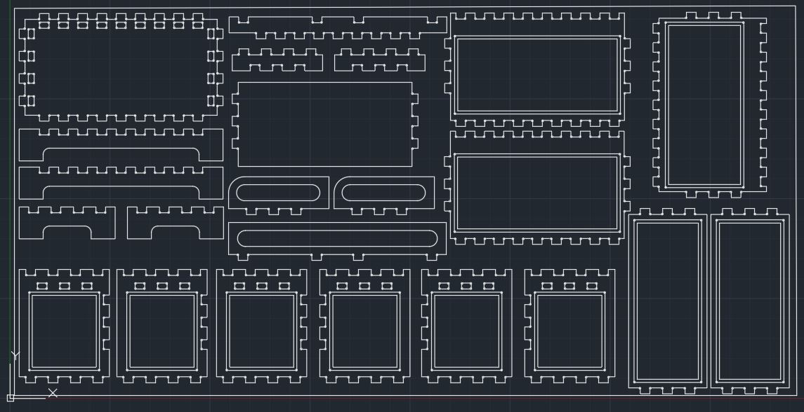 The outer line of the image represents the dimensions of the material to be cut.
Do not forget to use the overkill command of AutoCAD to eliminate unnecessary repeated strokes.
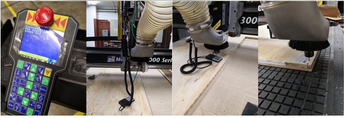
Preparing the machine
The material used is a 2.5m x 1.3m plywood plate.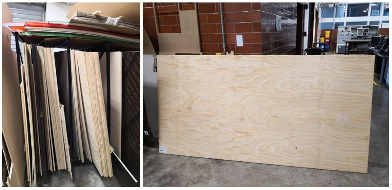 The first step is to place the plywood and screw it into the base and place some nails to hold it.
This can be done to prevent the wood from moving when cutting at high speed. It could be a very small piece and when passing the milling cutter, the piece to work could go off causing an accident.
The first step is to place the plywood and screw it into the base and place some nails to hold it.
This can be done to prevent the wood from moving when cutting at high speed. It could be a very small piece and when passing the milling cutter, the piece to work could go off causing an accident.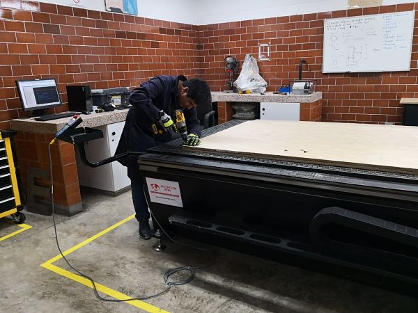 Then the machine and the suction system are switched on.
 To setup the zero position we use the control knob and a special tool following the following steps:
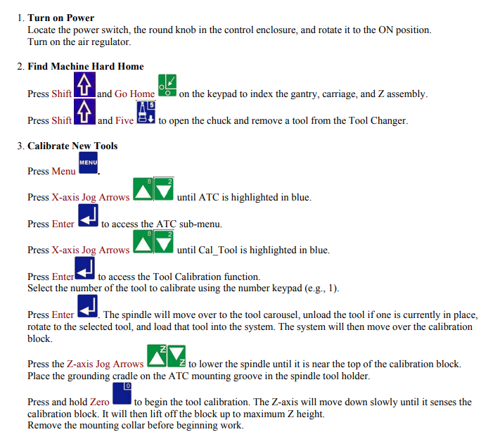 In the following picture the process of the configuration of the zero position is appreciated.
Manufacturing
The machine has several tools that are exchanged automatically using the M6 command of the G codes. In our case we will use the 3/16 " endmill. In order to be able to manufacture in an optimal way, we must carry out three types of work: internal displacement, external displacement and island filling.
Island filling
This work makes the 5 mm wear that I do in my design. It is done as a first job because it will not make deep cuts and you cannot move the plywood, the parameters that are used are the following.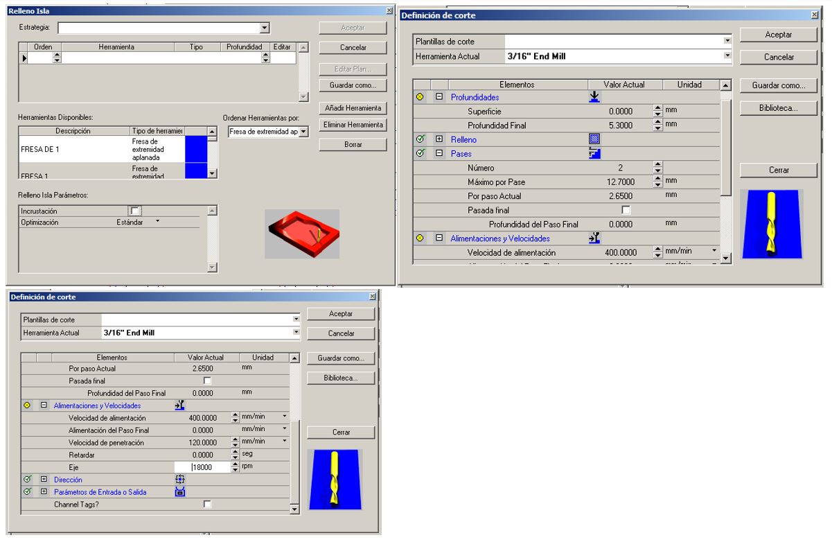
- Depth: 5.3mm
- Number of passes: 3
- Speed feed: 400 min/min
- Spindle Speed: 18000 RPM
Internal
The next work that is done is the interior cut. Once worn some areas of the design, the internal cut is made ensuring that the plywood will not move. The parameters that are used to make the cuts are the following.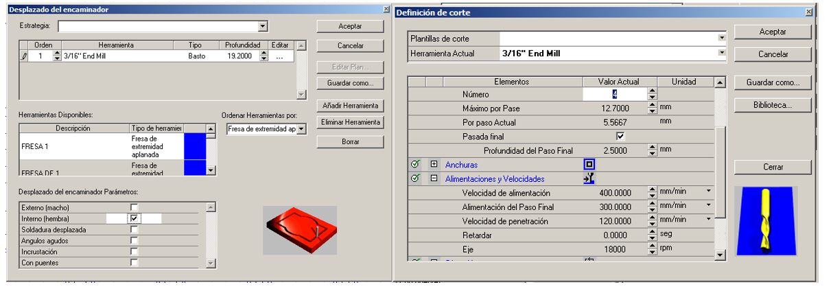
- Depth: 19.2mm
- Number of passes: 4
- Speed feed: 400 min/min
- Spindle Speed: 18000 RPM
External
The last work is the external cut, we must ensure the small pieces, so they do not move during the cut, the parameters used are the following.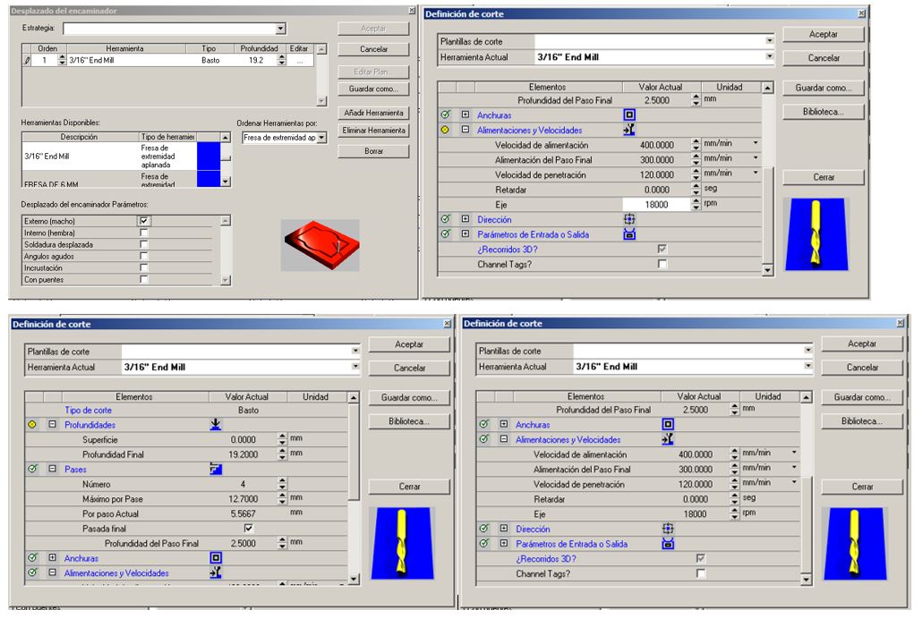
- Depth: 19.2mm
- Number of passes: 4
- Speed feed: 400 min/min
- Spindle Speed: 18000 RPM
Assembly
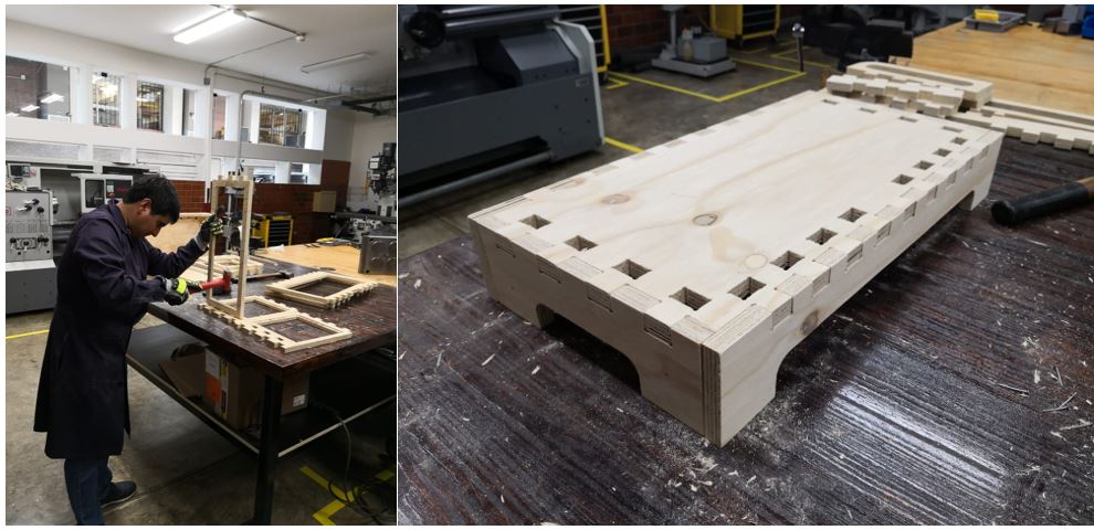
The result of the cut is shown in the following picture.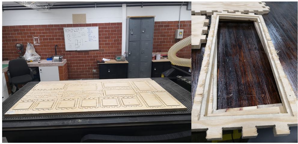 As you can see in the previous picture, it is necessary to sand all the pieces to start assembling it.
Once having all the pieces sanded and prepared, it is time to assemble the object.
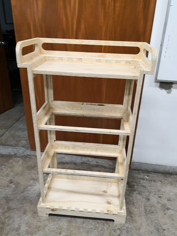
 And this is the final design.
Group
As a group work, several types of tests are performed with the multicam, as a personal contribution I made the following designs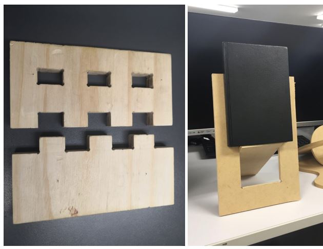 The objective of these tests is to check the cut tolerances in plywood. After these tests we realize that it is not necessary to give a tolerance, since it will enter under pressure without major problems.
To see all the documentation of the group work, you can visit the CIT page.
The objective of these tests is to check the cut tolerances in plywood. After these tests we realize that it is not necessary to give a tolerance, since it will enter under pressure without major problems.
To see all the documentation of the group work, you can visit the CIT page.
Problems
One of the main problems of the assembly are the tolerances and the correct design. In my case I had some small flaws in the design and the pieces did not fit perfectly.
For that reason I was forced to use some nails and glues to solve the problem.
Another problem is the excessive sanding of the wood edges on the edges of the furniture, it is recommended that it be sand-cut to the minimum to avoid that the pieces are very loose.
Download files
You can download this files Here (Inventor 2018):Base
Base
Front base (x2)
Lateral base (x2)
Central.
Back central part (x1)
Base central part (x1)
Left lateral central part (x1)
Right lateral central part (x1)
Final.
Final base part (x1)
Coupling back part (x1)
Coupling lateral part (x2)
Lateral final part (x2)
Back final part (x1)
Autocad (DXF)
Export file