Computer-Controlled Cutting.
For the assignment of the 4th week, it will be divided into 4 differentiated parts: parametric design, laser cutting, groupal assignment and vinyl cutting.
Parametric Design
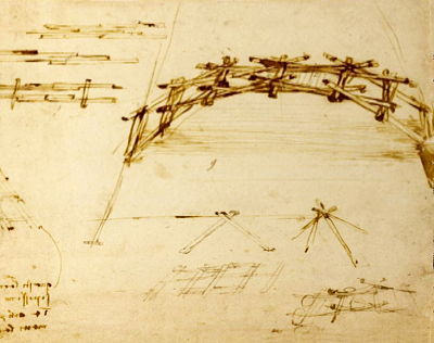
A design that is governed by certain logic which includes algorithms (to devise the logic) and these algorithms further include certain parameters which can be varied to see multiple outcomes.The idea that I have for this work is to make the bridge designed by Leonardo Da Vinci, but using a parametric model of all its pieces.
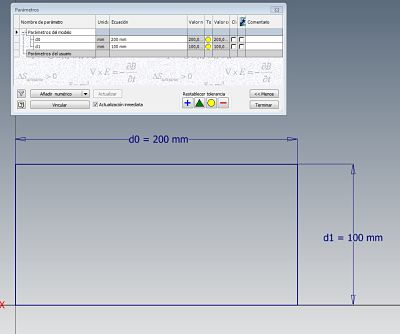
 The software used to create the parametric model is the inventor. To create parametric models, look for the function in the start bar. Below you can see a basic example of how to draw using parameters.
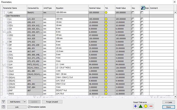
 After having added all the necessary parameters for our drawing, we have the following image in which we can see the parameters used and their relationship, as well as the measurement that some of them have that depend on a basic algorithm to obtain the final value.
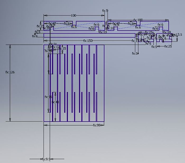
 I researched about live hinge designs, after a brief experimentation of different design, I made my own model with drawing parameters for later cutting. You can see the final drawing of what the first parametric cut experiment with the necessary parts would be.
It is very important to remove all degrees of freedom of design by creating horizontal, vertical and parallel restrictions. The next picture is my final 2d parametric design.
I researched about live hinge designs, after a brief experimentation of different design, I made my own model with drawing parameters for later cutting. You can see the final drawing of what the first parametric cut experiment with the necessary parts would be.
It is very important to remove all degrees of freedom of design by creating horizontal, vertical and parallel restrictions. The next picture is my final 2d parametric design.
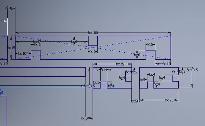
 This image is a detail of the parametric design created.
 This is the final assembly, which will be detailed later.
Laser Cutting
The laser cutter used in the CIT FABLAB laboratory is the Epilog Fusion M2.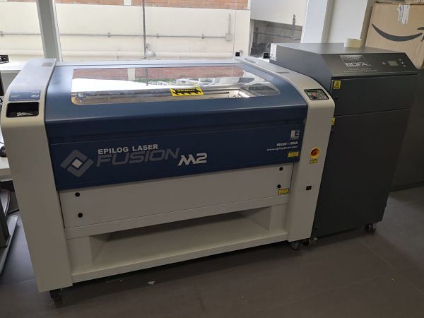
Tech Specs
The Laser source is State-of-the-art, digitally controlled, air-cooled CO2 laser tubes are fully modular, permanently aligned and field replaceable.Attach an air compressor are included to remove heat and combustible gases from the cutting surface by directing a constant stream of compressed air across the cutting surface.
In the following table a summary of the technical specifications of the laser cutter.
| Engraving Area. | 32" x 20" (812 x 508 mm). |
| Maximum Material Thickness. | CO2: 13.5" (343 mm) (2" lens) |
| Laser Wattage. | CO2: 30, 40, 50, 60, 75, or 120 watts |
| Size (W x D x H). | 52.5" x 33.75" x 40.75" (1334 x 857 x 1035 mm) |
Using the machine
While the experience of laser cutting is summarized almost as a normal impression, the machine needs some very specific steps to avoid accidents.It is very important not to leave the machine alone, you must supervise the work constantly in case there could be a fire.
The following explains the basic steps that must be performed with the machine, before using the Illustrator software, which will send the cutting instruction.
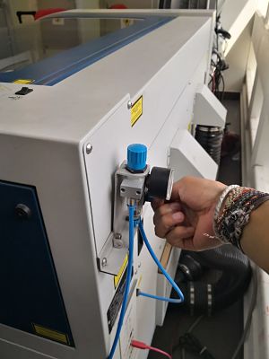
- You must open the CO2 valve, without this step the cut will never be made.
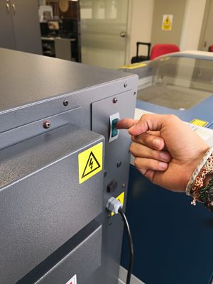
- We turn on the air filter, to avoid accidents.
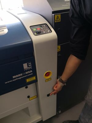
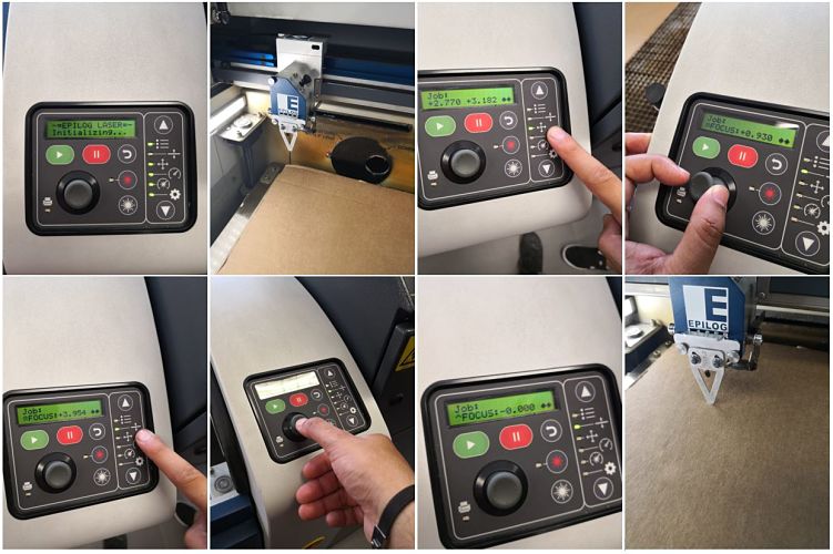
- We turn on the laser cutter, as shown in the picture.
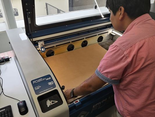
- We introduce the material to be cut, in this case we use 3mm corrugated cardboard.
- Set the zero point as seen in the picture. A metal piece is used as a zero sensor and the work bed is moved with the panel selector, when the desired zero position is achieved, the selector is pressed. The complete procedure is observed in the following pictures:
Kerf
In order to make a more precise cut, we must take into account the kerf, since the measures cut may not be exactly the same as the measures designed.
To check these parameters, I will make a basic design and check the measurements.
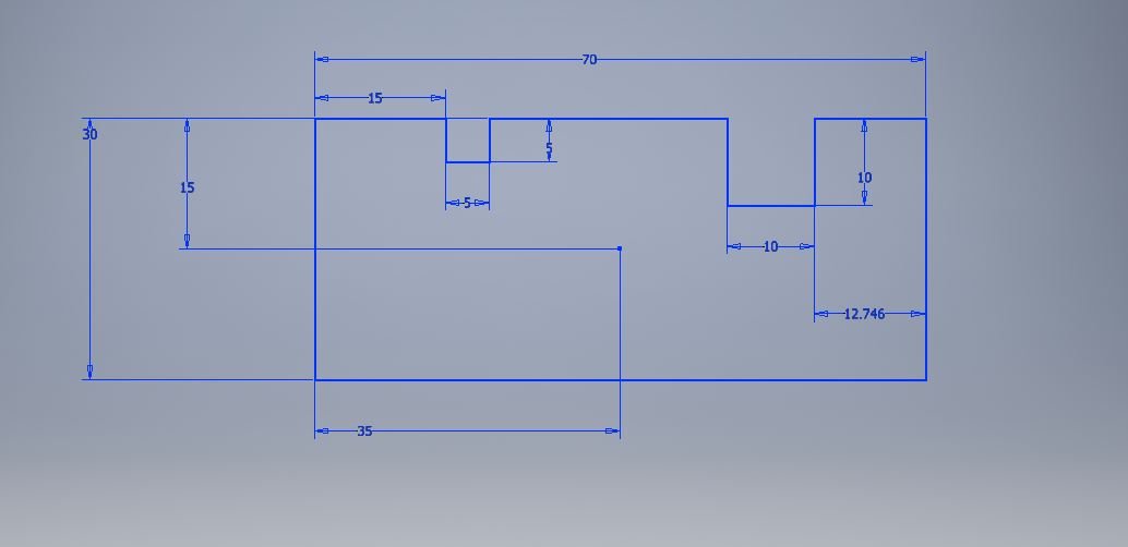
Measure in milimmeters
Once the cut is made, we proceed to measure the design using a vernier, as seen in the picture.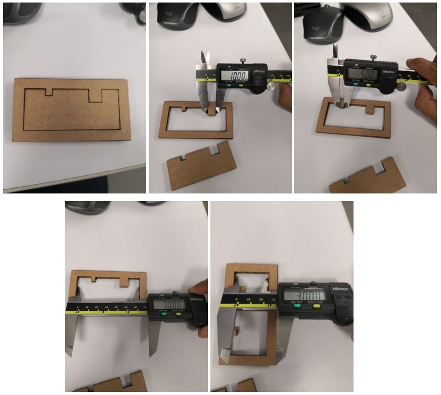
Exterior
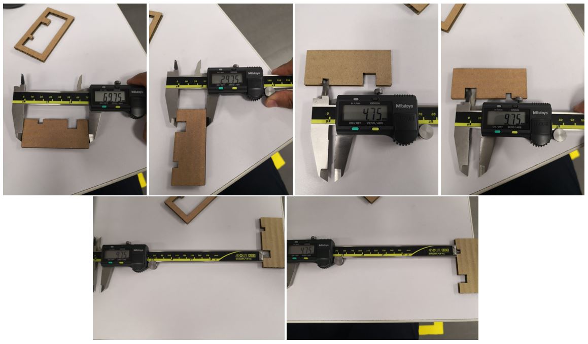
Interior
We can observe that we must have a consideration of 0.25mm of tolerance in the inner cuts for our designs.Create and Assembly
Once the parametric design has been obtained and the laser cutter has been prepared, it is time to use software to make the cut. The software used is the Illustrator, this software can identify both vector and raster designs, although it works better in the vector format.Export files
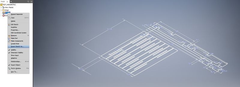
The process that is carried out in the laboratory is the following:- First, the inventor's file is exported to an Autocad format ,because of the compatibility it has with the Illustrator, for this is done from the sketch as shown in the picture.
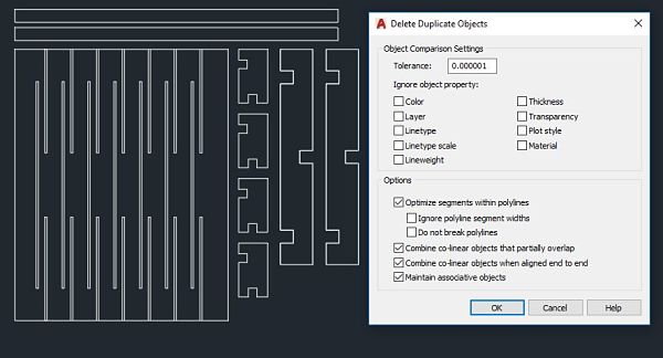
- From the software AutoCAD we adapt the parametric design to optimize the space. We use the overkill tool to eliminate any type of repeated line. If we leave double lines, the cutter will pass as many times as there are lines and an accident could happen.
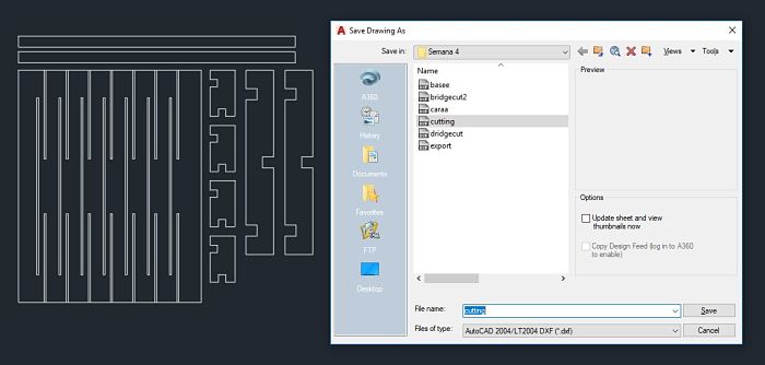
- We save the file in AutoCAD 2004 format for use in the Illustrator.
Parameters configurations
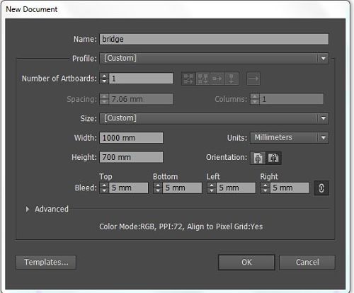
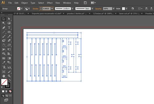
The Illustrator software will be used for laser cutting and vinyl cutting, which will be seen later. This software works with vector images, which is the format that interprets the cutters, everything must be in vector.From the illustrator software we create a new document using the measurements of the work area of our laser cutter, as shown in the picture.
 We look for our file and we arrange it in the work area, it is very important to place the Stroke in 0.00025mm, after several tests in the laboratory, it is the indicated value for the cutter to know that it is a vector and make the cut.
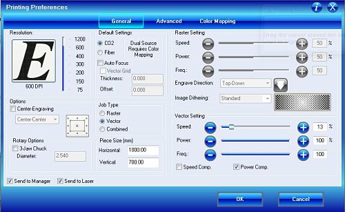
 As if it were a printer, the file is sent to print, but the laser cutter is chosen as the printer, we remove the Auto-Rotate and enter the Setup of the laser cutter to configure the cutting parameters.
The work type is vector and choose the parameters of the picture. The chosen speed was after some attempts of cutting without getting to burn the material.
| Job Type | Vector Setting |
|---|---|
| Vector | Speed: 12% Power: 100% Freq: 100% |
Cutting
To demonstrate the cut, I made a video using the free editor Kizoa for the edition and uploaded to the Youtube platform.Assembly
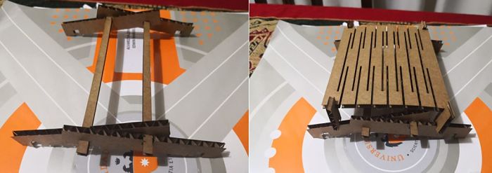
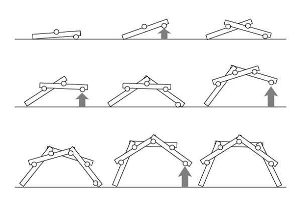
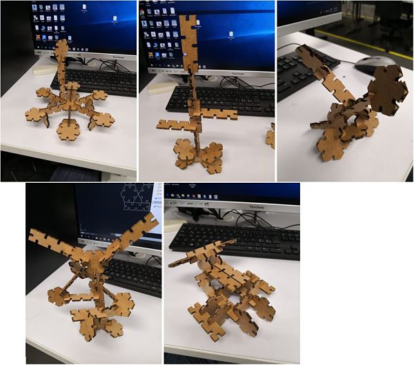
Once the pieces are cut, it is time to build our bridge. In the picture you can see two similar pieces, since the first attempt could not be assembled well. For that reason I was decided to change the height parameter and be able to assemble it.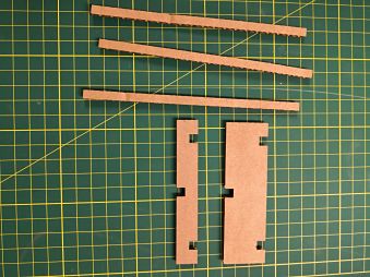 Being a design by Leonardo Da Vinci, there is a small tutorial of the best form that can be assembled, as shown below
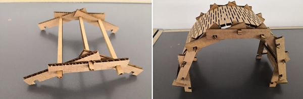
 A first assembly with the first design with the final design is shown below, the change can be observed.
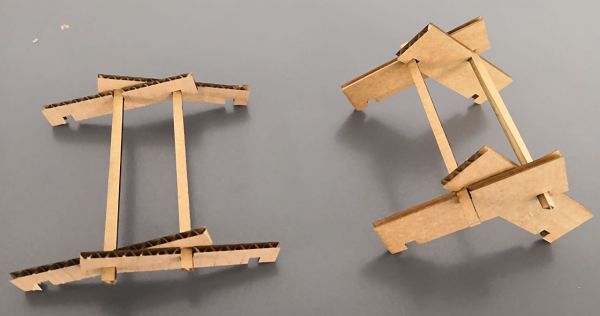 As you can see the design on the right, the side blocks of the bridge are too big and makes the bridge deform with a new block.
The objective of the stability of the bridge is to have the blocks as long as possible with respect to the width, so we can have a wider structure.
As you can see the design on the right, the side blocks of the bridge are too big and makes the bridge deform with a new block.
The objective of the stability of the bridge is to have the blocks as long as possible with respect to the width, so we can have a wider structure.The final and assembled press-fit kit is shown in the following image.
Press-fit Construction Kit
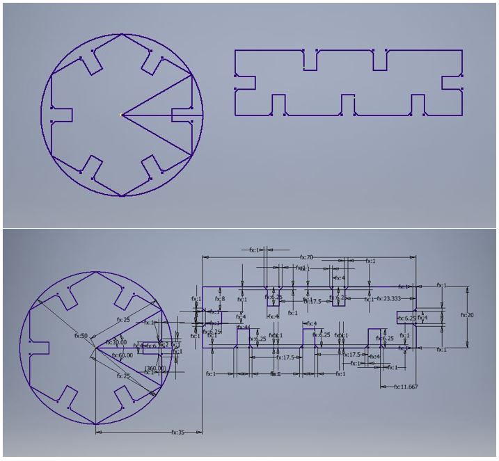
Once the bridge is made and knowing the cutting parameters of the machine, it is time to create a basic press-fit construction kit. The design contemplates a polygon and a rectangle with inserts to be able to unify them and create designs. We can see all the parameters used for our design in the following picture.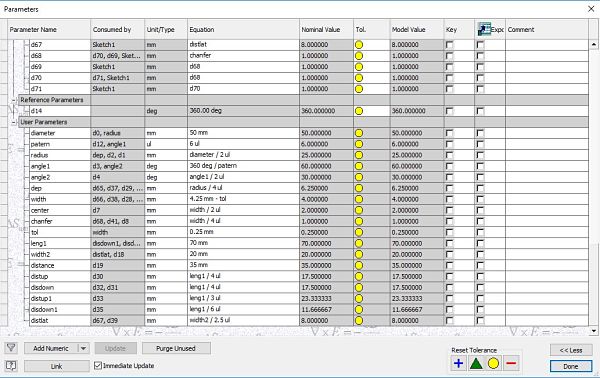 To make the polygon is done knowing the amount of sides that we want to obtain from our polygon and divide it by 360º.
The parameter width is the same that corresponds to the material and we create a parameter called tolerance, this parameter was obtained after 4 cuts and we obtain 0.25mm with respect to the material used: cardboard.
We can observe the design used in the image:
To make the polygon is done knowing the amount of sides that we want to obtain from our polygon and divide it by 360º.
The parameter width is the same that corresponds to the material and we create a parameter called tolerance, this parameter was obtained after 4 cuts and we obtain 0.25mm with respect to the material used: cardboard.
We can observe the design used in the image:
 After cutting several pieces, you can create the following designs.
Groupal Assignment
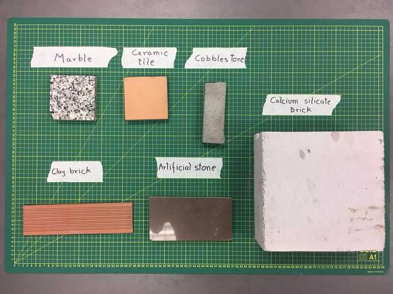
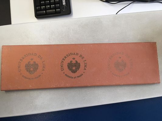
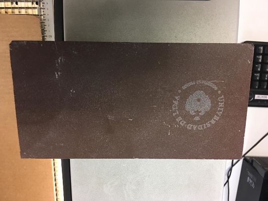
In the group work, we decided to test the laser cutter making engravings to various types of stones that we got in the university, in this way we test the parameters and how well it records in this material.My contribution was the test of some Raster of the Logo of University of Lima. The picture shows all the stones that we used.
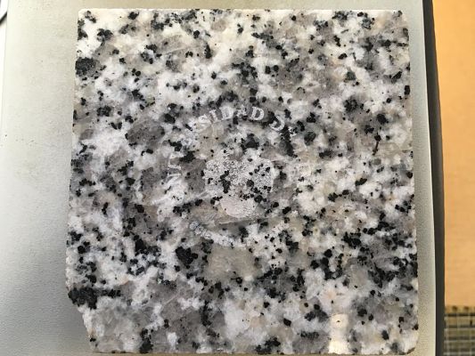
 In the following table we can observe the parameters of raster used and the result of each stone
| Stone | Parameters | Result |
|---|---|---|
| Marble | Speed: 40% Power:100% Freq: 50% |
 |
| Ceramic Tile | Speed: 45% Power:100% Freq: 50% |
 |
| Coblestone | Speed: 10% Power:100% Freq: 50% |
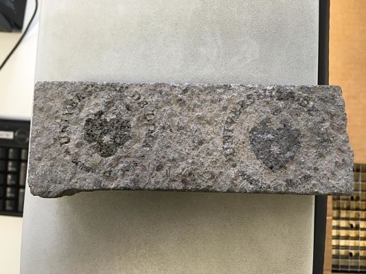 |
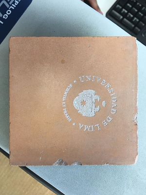
| Clay brick | Speed: 25% / 10% / 70% Power:100% Freq: 50% |
 |
| Artificial Stone | Speed: 15% Power:100% Freq: 50% |
 |
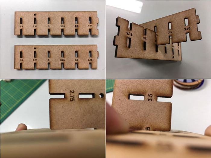
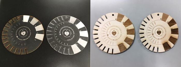
The next test was the creation of "combs" and "discs" to check the cutting tolerance and the fit between them. The discs were made by a group of students called CEFADI. The result is shown in the Picture.
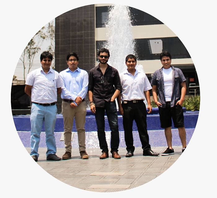
As last group work, Grasshopper software was used, this allows us to do parametric design from an image. The image used was a group photo of the students and managers of the CIT for the FabAcademy.
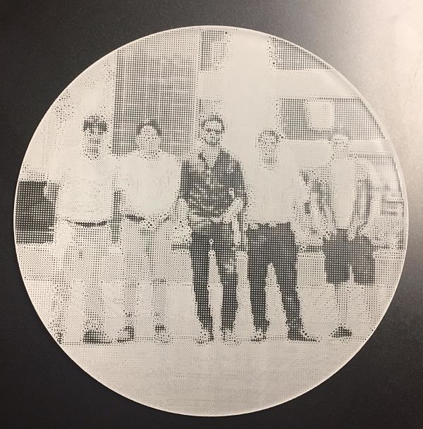
 Parameters are used to generate the pixels of the image in the X-Y plane.
A point is established that represents each pixel and is associated with an array of the image to create the base of the imgen, which in this case are circles.
Parameters are used to generate the pixels of the image in the X-Y plane.
A point is established that represents each pixel and is associated with an array of the image to create the base of the imgen, which in this case are circles.
 The result is the following picture.
 You can read more about our work in the CIT web Page
Vinyl Cutting
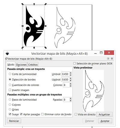
The last part of this assignment I decide to cut a Protoss Logo, from the video game Starcraft.The logo was downloaded from the official forum of the game, where many players create their own fan arts and other drawings alluding to the game.
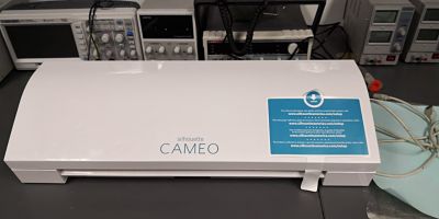
We only use the vinyl cutter machine, we have in the lab the machine Silhouette Cameo
 After downloading the internet image, we use the Inkscape software to vectorize the Protoss logo.
In the picture we can see how to carry out the process.
After downloading the internet image, we use the Inkscape software to vectorize the Protoss logo.
In the picture we can see how to carry out the process.
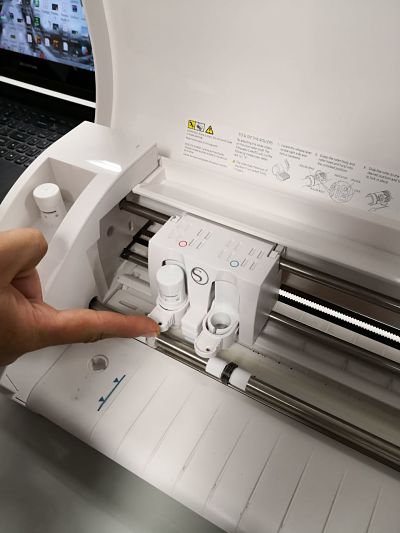
 To start cutting, we must prepare the machine following the following steps:
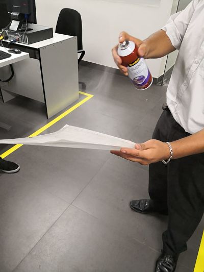
- Stick the vinyl in a template.
- Ensure the tooling in the machine.
- Put the template and load.
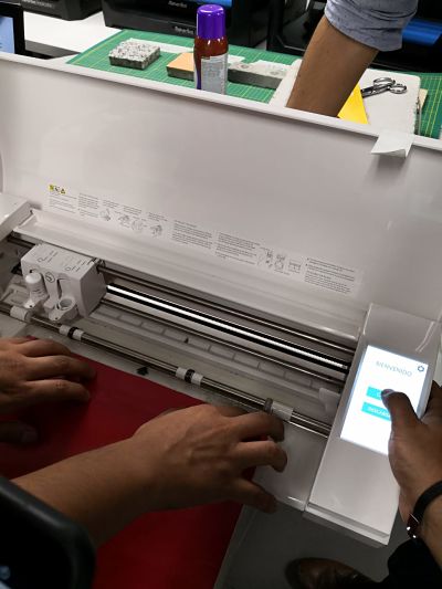
- We define the work area.
Width:297mm
Height: 300mm - Load the logo.
- After several tests in the laboratory, we use the following cutting parameters.
Vel: 7
Pres: 1
Pass: 1
Below is an image of the process of cutting the design.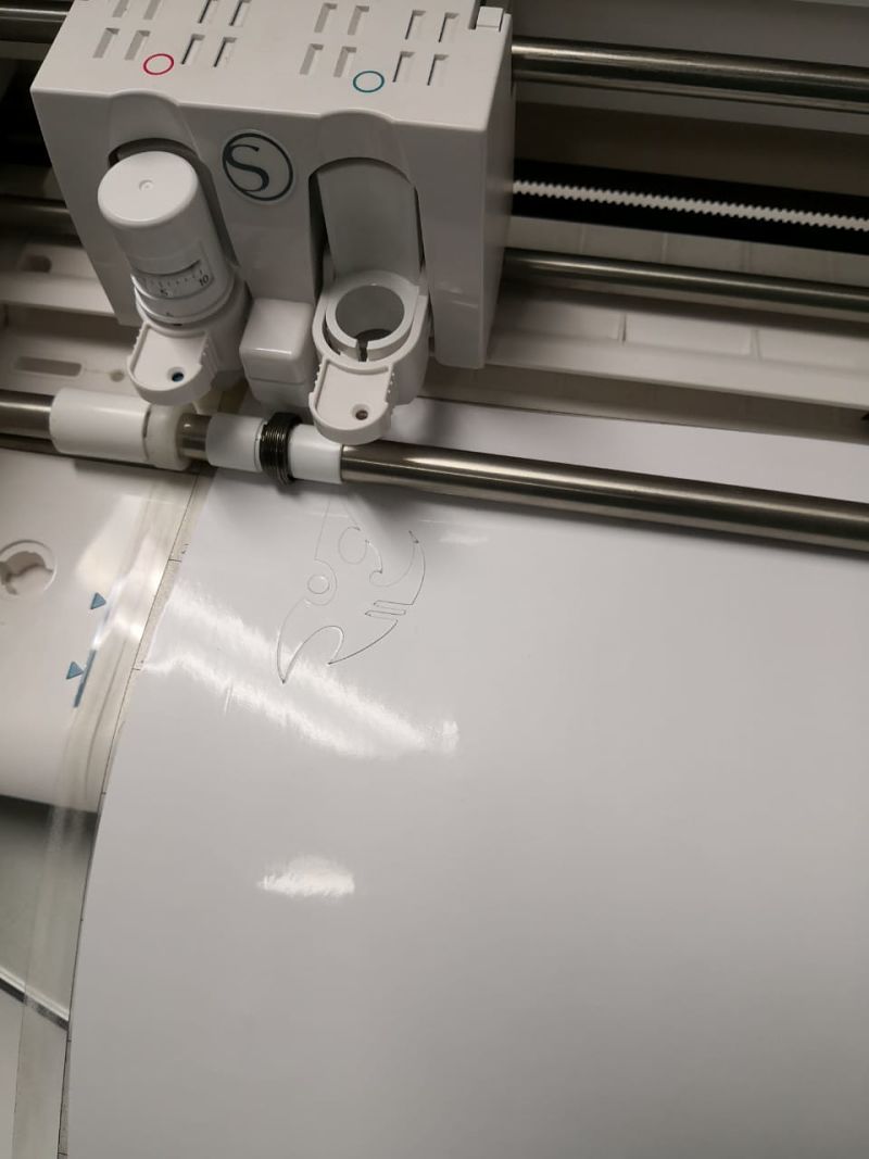
- At the end of the cut, we must download the template with the cut
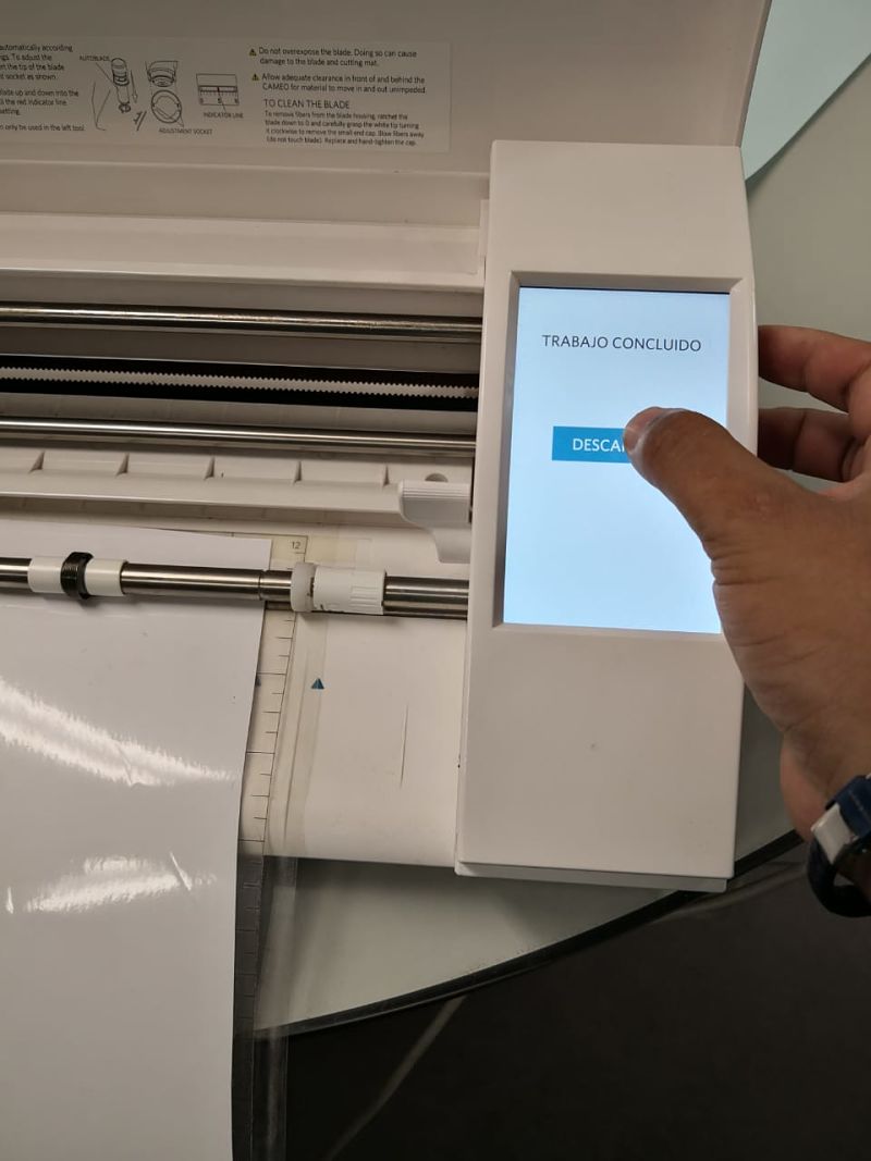
- The vinyl is removed as if it were a conventional sticker.
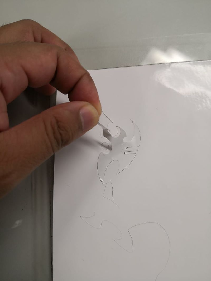
- Finally, this is the result of the vinyl cut.
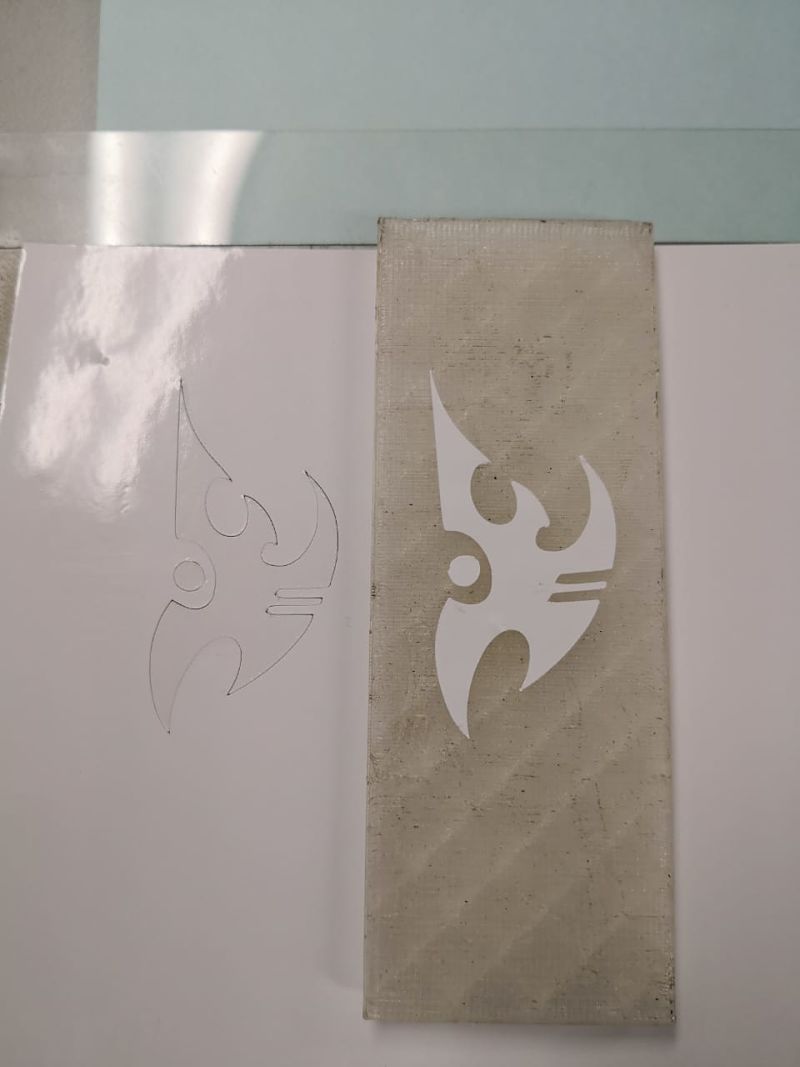
It is necessary to stick a sheet with an adhesive face to the vinyl design, take off the vynil and finally paste the design in the final place. I found a video of how these steps should be done.
Download files
You can download this files Here:Bridge parametric Design.
Press-fit kit.
Protoss Logo Vector. (Inkscape)
Protoss Logo Vinyl.
Kerf design.
Bridge .dxf.
Press-fit kit .dxf.