
Wildcard Week.
Design
As I talked about myself, my favorite sport and hobby is archery, which I practice constantly and I usually participate in local competitions, that's why I decided to create a very important implement, the finger tab.
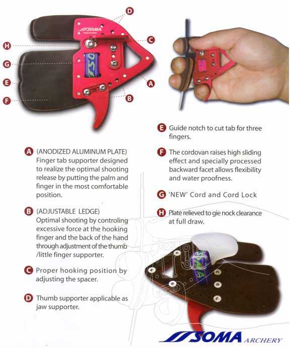
Source: https://www.bowsports.com/acatalog/Soma_-_Saker_Tab.html
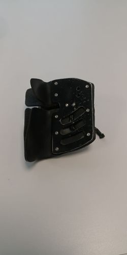
Particularly I use the cordovan cavalier, as shown in the picture.
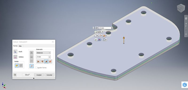
 Based on my own tab, I do the design using the Inventor software, the result is as follows. The thickness is 3mm.
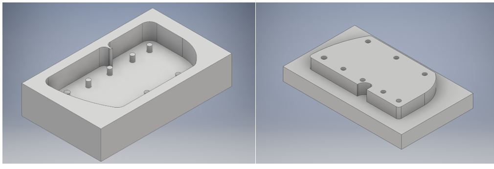
 Once the design is done, I proceed to create a mold with the positive and the negative part to be able to make the mixture of the fibers for the assignment.
 With these designs I proceed to the manufacture.
Molding manufacturing
Unlike the week of manufacture of molds with the machinable wax, I will use an aluminum block for this process using a new CNC machine, the Kitamura Mycenter 3XG milling machine.
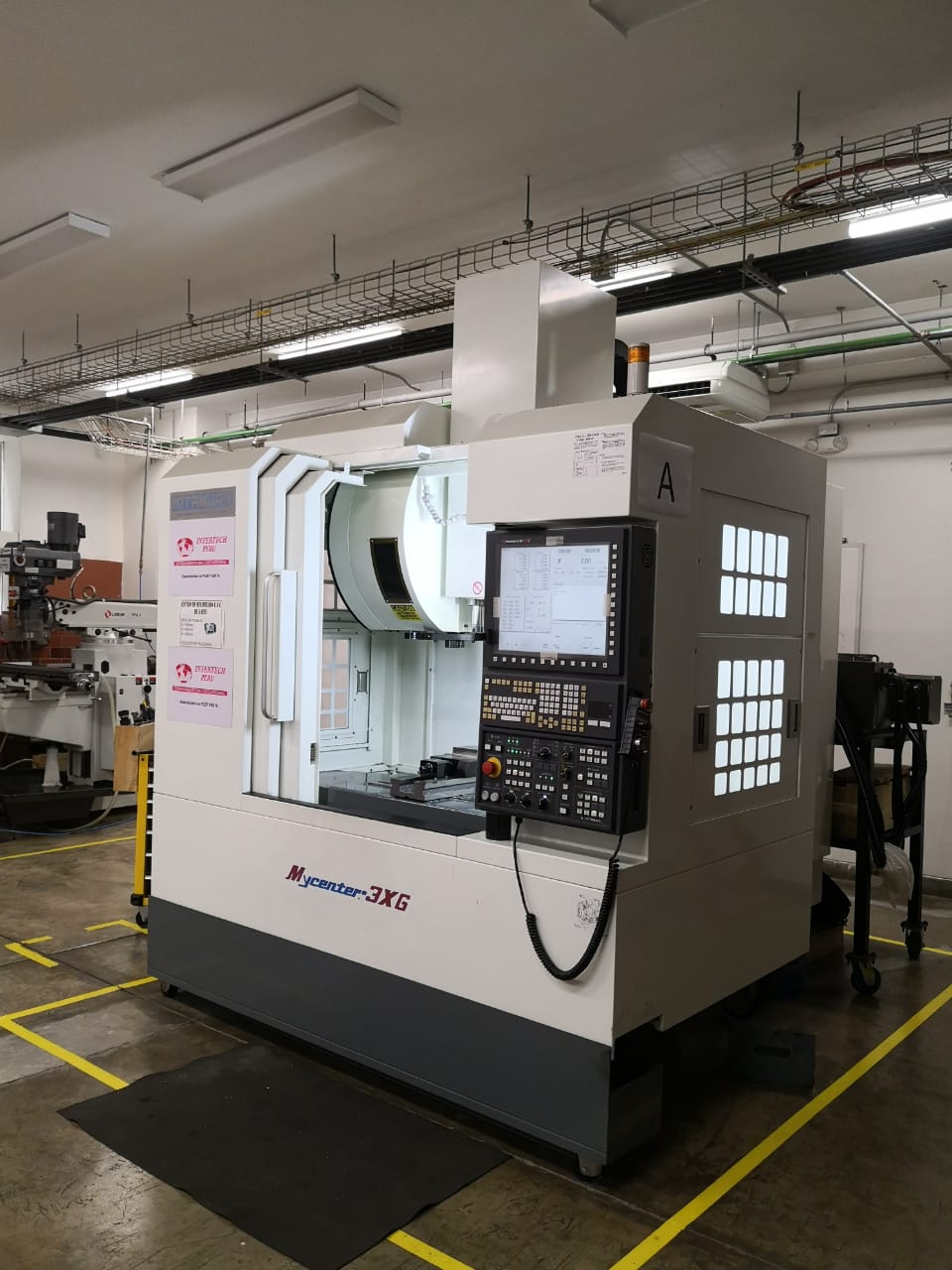 The Mycenter-3XG features positioning accuracy of 0.000079" and repeatability of 0.000039".
All mounted surfaces requiring assembly are hand-scraped in order to provide the full surface contact and proper alignment that exceed the fit and finish of mounting surfaces when machined.
The Mycenter-3XG features positioning accuracy of 0.000079" and repeatability of 0.000039".
All mounted surfaces requiring assembly are hand-scraped in order to provide the full surface contact and proper alignment that exceed the fit and finish of mounting surfaces when machined.
The following table shows the specifications of the machine:
| Table Size | 16.1"x34.0"(410x864mm) |
| Travel (X,Y,Z) | 30"X18"X18.1" (760X455X460mm) |
| Spindle Taper | NST No. 40 |
| Spindle Speed | 40~15000 rpm |
| Tool Storage Capacity | 30Pcs. |
| Tool Change Time (T-T/C-C) | 2.2 Sec /4.4 Sec |
| Rapid Feed (X,Y,Z) | 1969ipm (50m/min) X/Y x 1417ipm (36m/min) Z |
| Power Requirement | 30KVA |
Here is a video of demonstration of the machine with the 5-axis accessory.
The next step is generating the G-code with the software Edgecam with the help of the laboratory technician, since he has mastery of the use of the machine and by laboratory rule he manipulates the machine. A 4 mm endmill is used and the zero position of the Z axis must be configured with the sensor, as shown in the picture.
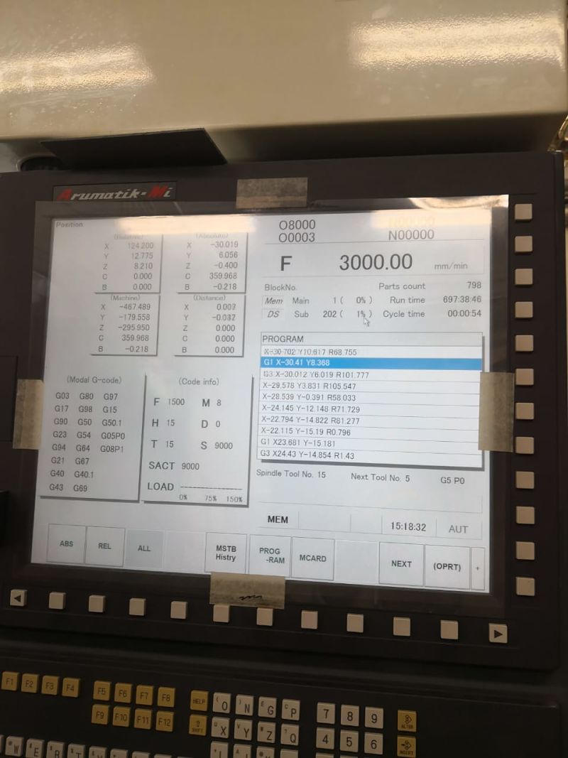
 We get the g code of our files and they are incorporated into the machine.
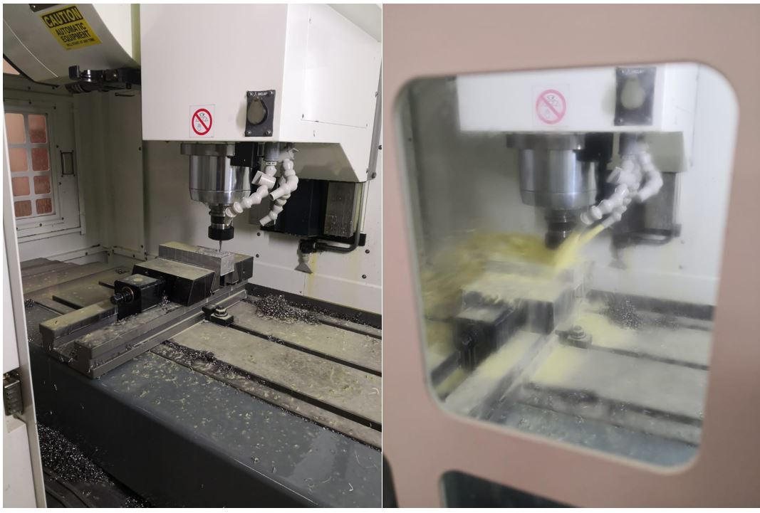
 Now it's time for the machine to start working to get our mold.
 We can see below the results obtained from the machining.
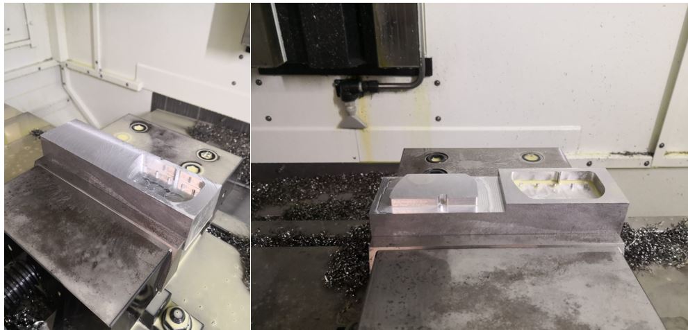 Afterwards, some holes are incorporated that will guide us to have the mold perfectly fitted and we cut the piece to have the molds separately.
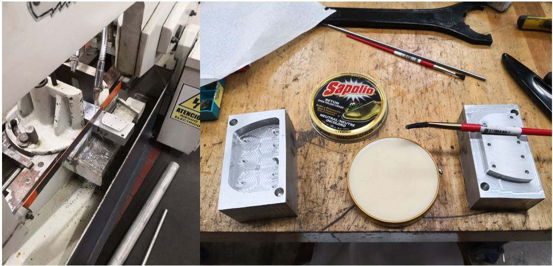 In the image you can see the separate molds and a shoe polisher, this will serve for a simple demolding.
Composites
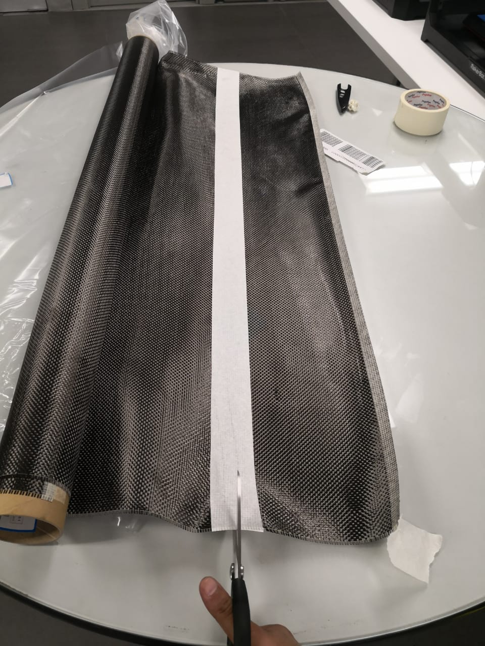
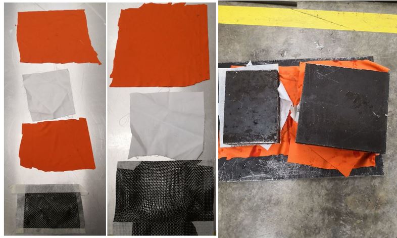
The composite materials are 2: Carbon fiber (carbon fabric 160g / m2) and a cotton fabric.
I chose 100% cotton between polyester and cotton knit because it seemed better idea to have a more robust composition and higher density to get a more doubtful product.
The documentation of the fiber can be found here: https://www.mtec-akademie.de/seminare/leichtbau-composites-carbon.html
To be able to cut the fiber, it is necessary to use an adhesive tape to avoid dismantling the carbon fiber. Cotton is not necessary to use the tape due to its density.
 The 4 layers of shoe polisher mentioned above are added.
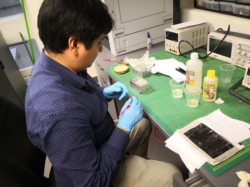
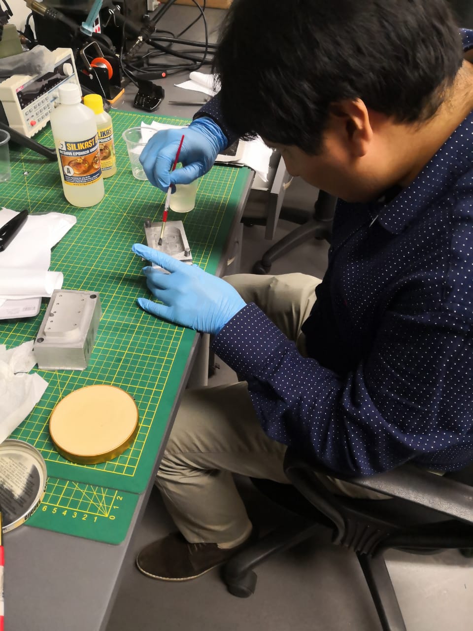
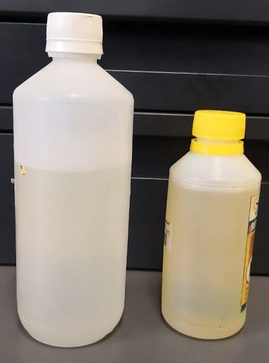
 The resin is prepared separately, in this case I used the Silikast Epoxy Cristal. The mixing ratio 2: 1 and the curing time 8 to 12 hours.
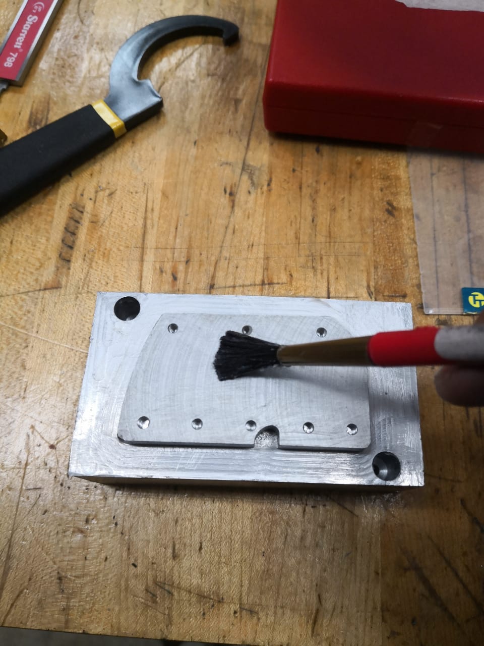
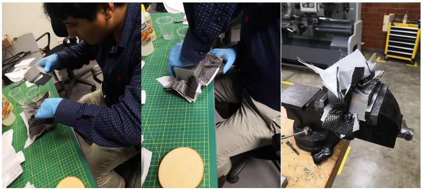
 Once the mixture is made, we begin by covering the mold with a layer of resin.
 We proceed to place a fiber layer very carefully.
 After placing the fiber layer, add another layer of resin and the cotton fabric, checking that the fibers are in opposite directions so that they can adhere in an optimal way.
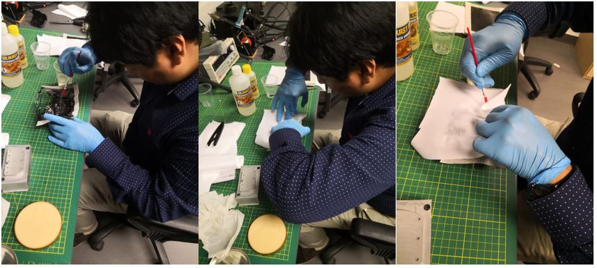 We carry out the same process with the following configuration: fiber, cotton, fiber, cotton and fiber.
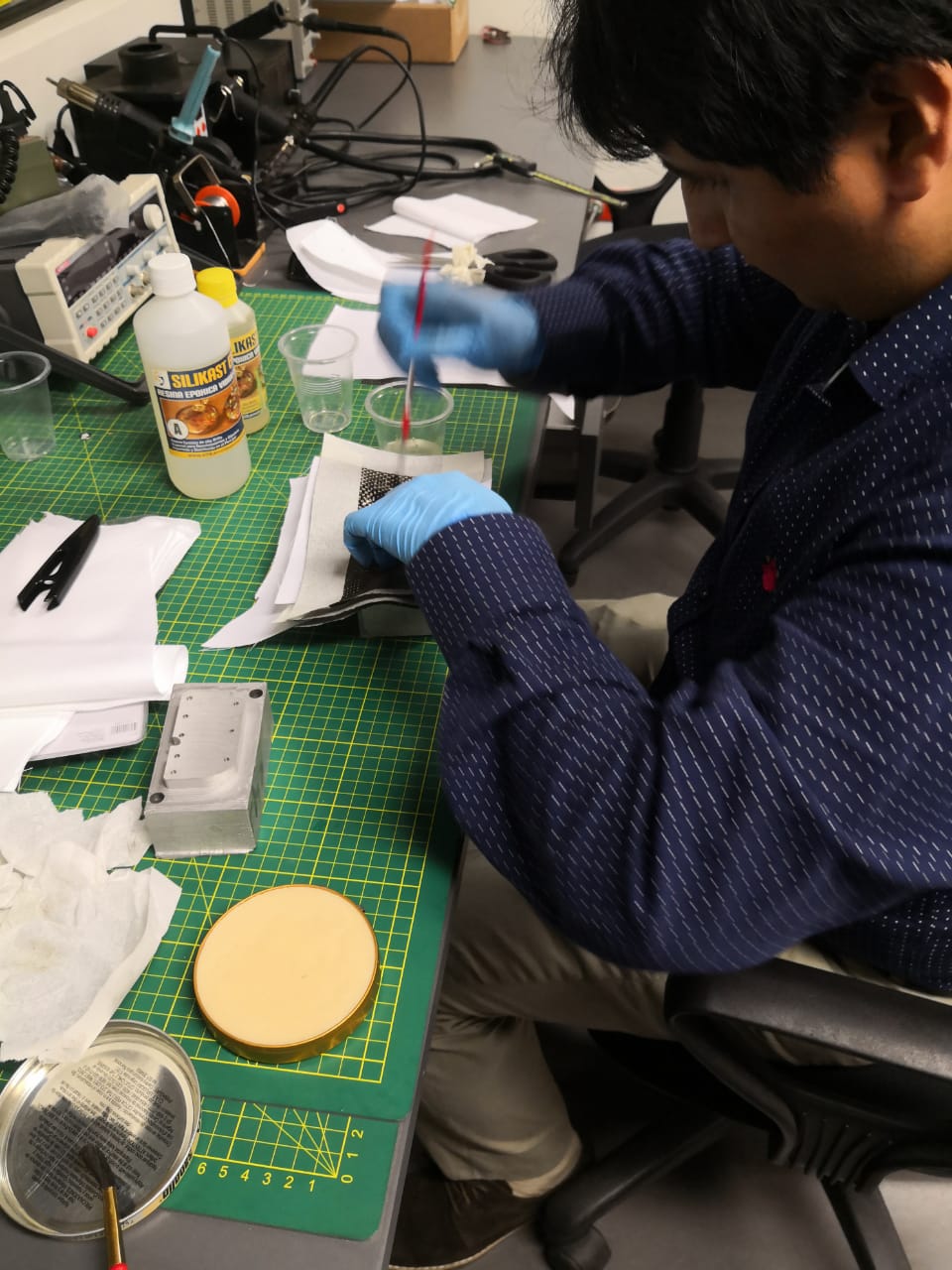 Once all the layers are put on, the mold is closed and left to rest until the resin dries.
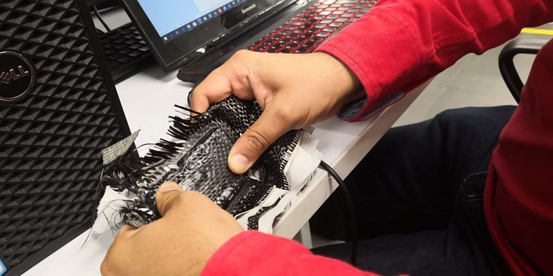
 After the drying time, we obtain the following result.
Problems
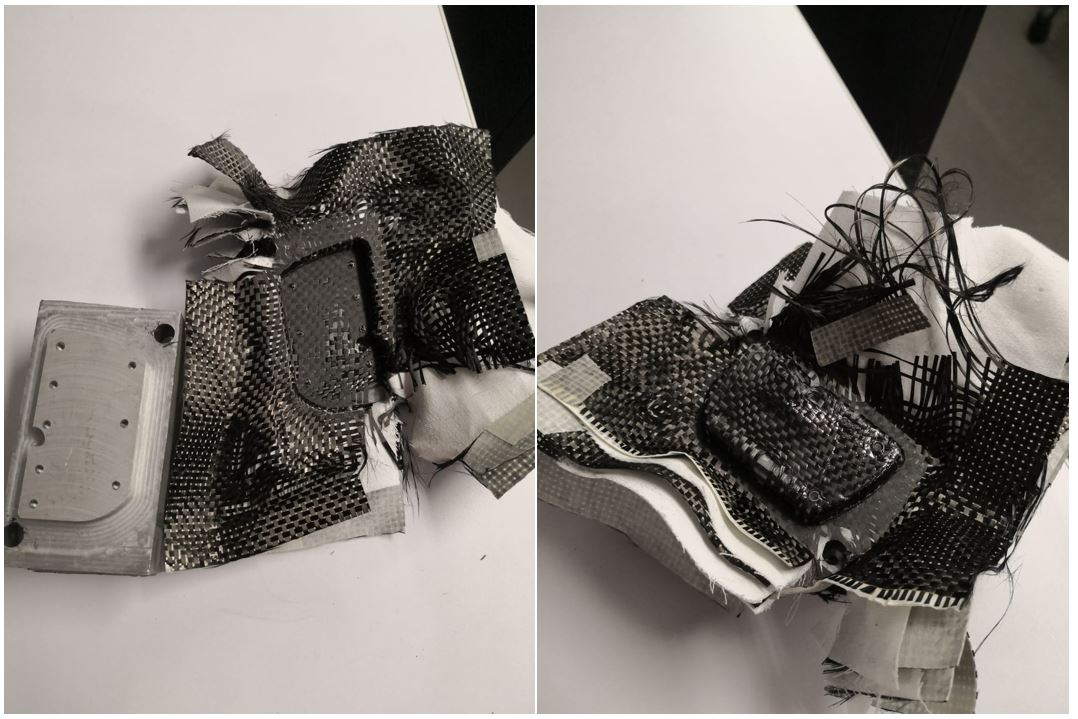
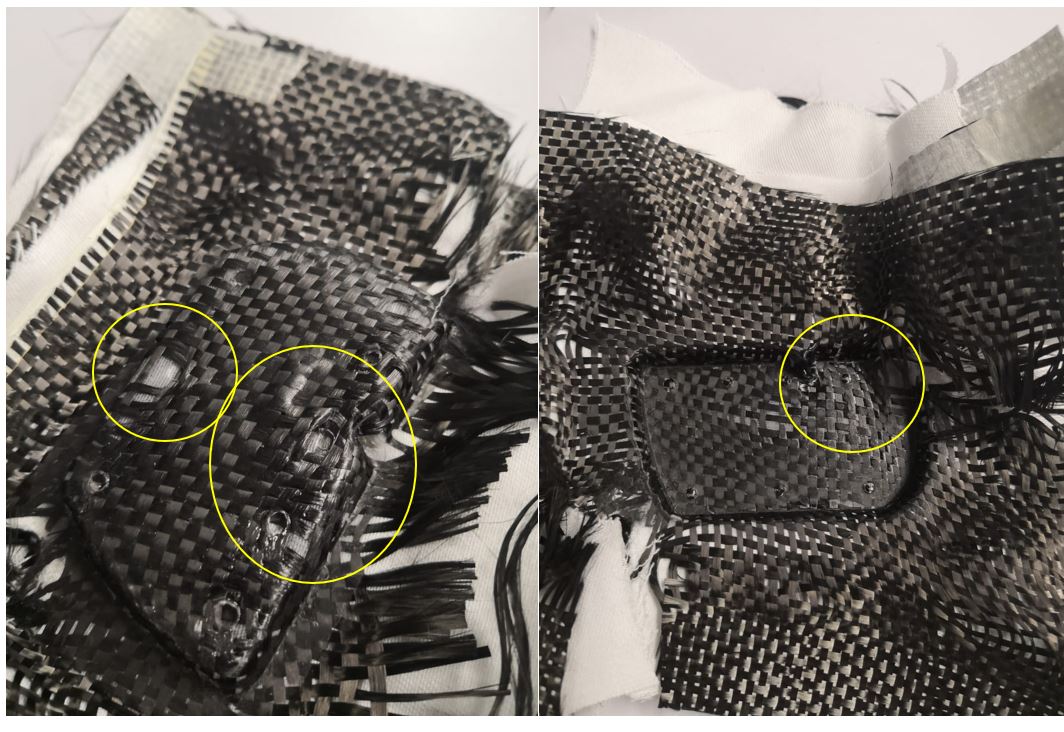
Once unmolded we see that the result is not desired for several reasons:
Resin
The product has not been glued in an optimal way, since there should be several layers of resin between the fabrics so that it can enter between layer and layer.I could also see that the proportion of resin mixture was not optimal when seeing the wear between both components.
Mold desing
Another error that is appreciated is in the design of the mold. The mold concept that I used was for plastic injection or liquid resin. To prevent the composites from becoming deformed, curves and elements that can be seen in the picture must be avoided.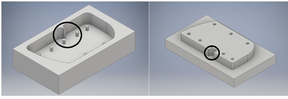 With this mold we have a deformation in the composite that does not allow a good finish.
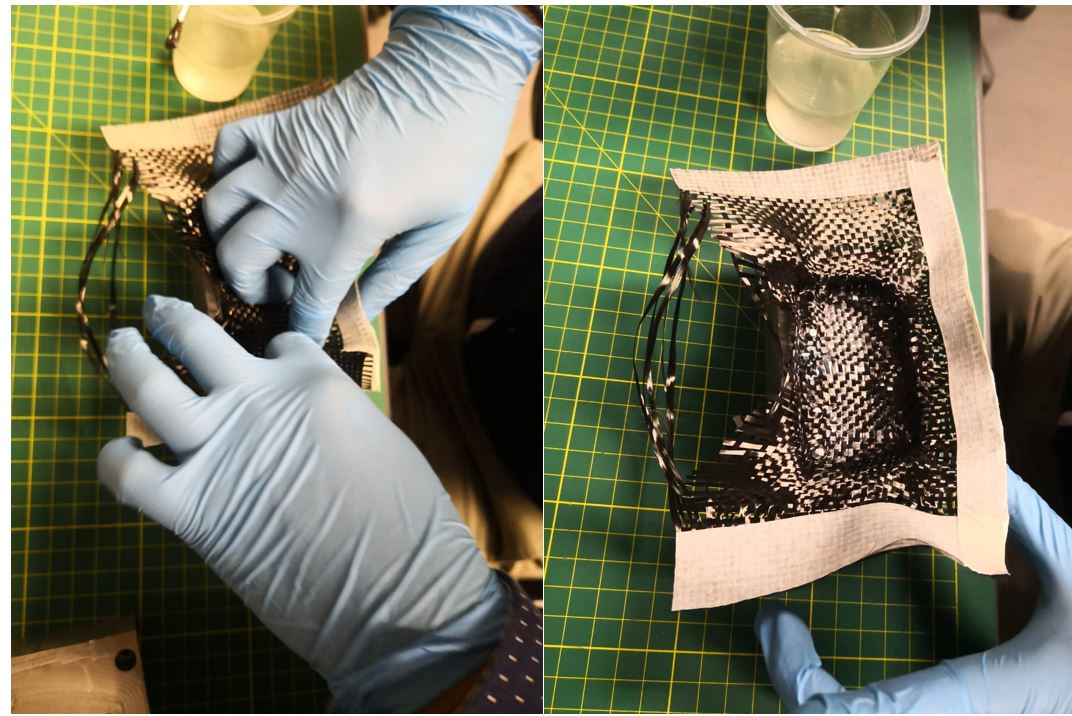
Layers
It also had to make another configuration of the distribution of the composites, only the fibers were placed vertically and horizontally, as can be seen in the picture.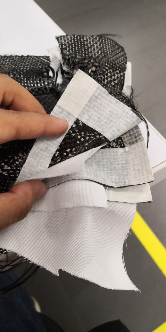 When having this configuration, the product is strong in these senses, but it can be deformed if it is blent on the side.
Solution
One solution to avoid all these problems is to use a flat mold and then perform profiling with a CNC, use more resin with a correct composition, the configuration of the location of the composites.If you want to recover this product you could use a last layer of fiber to obtain an aesthetic and rigid result.
More consideration
Other considerations of the failure obtained is by the measurement of our design. Being a slightly thicker than expected design, other types of fabrics would have to be used, since the resin's objective is to interlace with the fabrics and to harden enough to make the product more stable. It is recommended to use the exact amount of cloth and if it is necessary to make a laser cut.For a future design will take into account the size of the piece, have a better quality fabric so that the resin is better mixed and leave at least 12 hours of waiting until salgoa the final product.
Group
For this week, some small composite tests of squares with fiber configurations were carried out.My personal contribution was to use a 4 fiber configuration and see the results.
 To see all the documentation of the group work, you can visit the CIT page.
Download
You can download this files Here:
Tab design (.obj).
Positive design (.obj).
Negative design (.obj).