
Networking and communications.
Communication
The objective of this week is to make a communication between at least two boards using any communication protocol between microcontrollers. In my case I use the serial communication protocol.
 A benefit of serial communications is low pin counts. Serial communications can be performed with just one I/O pin, compared to eight or more for parallel communications.
Some characteristics of serial communication are the following:
A benefit of serial communications is low pin counts. Serial communications can be performed with just one I/O pin, compared to eight or more for parallel communications.
Some characteristics of serial communication are the following:
- On an asynchronous bus, data is sent without a timing clock. A synchronous bus sends data with a timing clock.
- Full-duplex means data can be sent and received simultaneously. Half-duplex is when data can be sent or received, but not at the same time.
- Master/slave describes a bus where one device is the master and others are slaves. Master/slave buses are usually synchronous, as the master often supplies the timing clock for data being sent along in both directions.
- A multi-master bus is a master/slave bus that may have more than one master. These buses must have an arbitration scheme that can settle conflicts when more than one master wants to control the bus at the same time.
- Point-to-point or peer interfaces are where two devices have a peer relation to each other; there are no masters or slaves. Peer interfaces are most often asynchronous.
- The term multi-drop describes an interface in which there are several receivers and one transmitter.
- Multi-point describes a bus in which there are more than two peer transceivers. This is different from a multi-drop interface as it allows bidirectional communication over the same set of wires.
Source: https://i.ytimg.com/vi/JpcKF0-MZsg/maxresdefault.jpg
From the attiny45 datasheet you can see that The Universal Serial Interface (USI), provides the basic hardware resources needed for serial communication. Combined with a minimum of control software, the USI allows significantly higher transfer rates and uses less code space than solutions based on software only.There is also another communication protocol, the USI two-wire mode is compliant to the Inter IC (TWI) bus protocol, but without slew rate limiting on outputs and without input noise filtering. Pin names used in this mode are SCL and SDA.
It is only the physical layer that is shown since the system operation is highly dependent of the communication scheme used. The main differences between the master and slave operation at this level is the serial clock generation which is always done by the master. Only the slave uses the clock control unit.
Board
In order to understand the serial communication, I decide to make the Neil examples, specifically the Hellobus.
These boards consist of two parts, the bridge and the node.
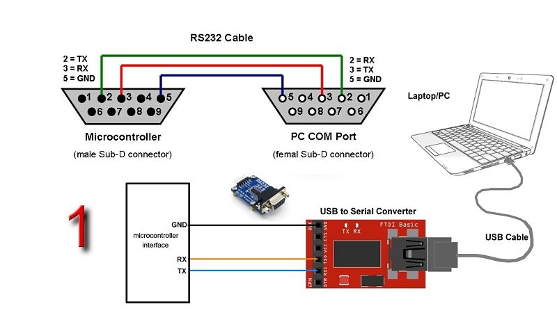
The main feature of the bridge are the connection pins for the use of the Rx and Tx terminals of the microcontroller with the computer through an FTDI.
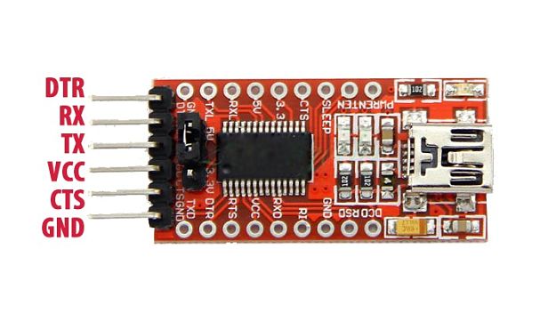
Source: http://lechacalshop.com/gb/various/36-ftdi-usb-to-ttl-serial-converter-adapter-ft232rl.html
In order to better understand the serial communication, I decide to make 1 bridge and 3 nodes, as you can see in the following picture.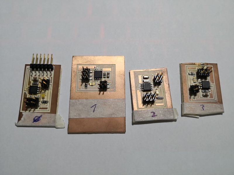
Input communication board
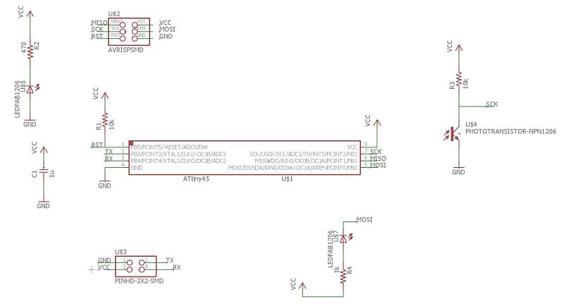
Thinking about the final project, I decide to create a board that incorporates an analog sensor, for this I use an LDR, which varies the output signal according to the amount of light it emits, this sensor can be a simulation of the level of the tank, pressure, etc.
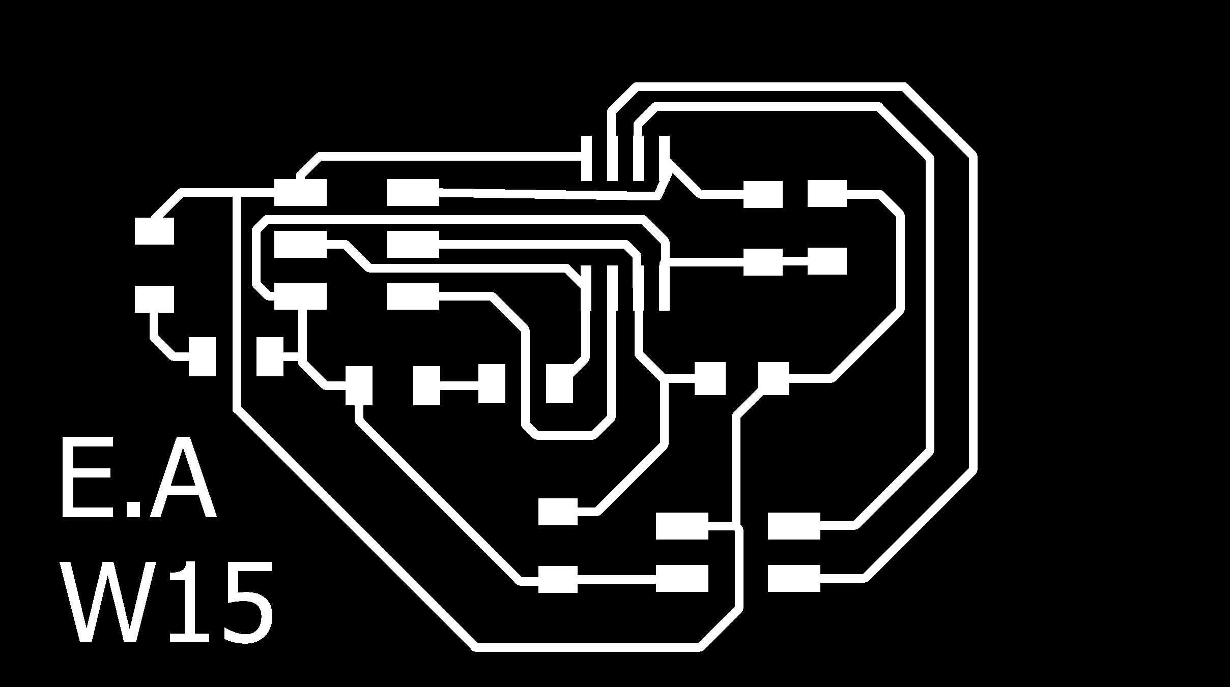
The design of the schematic circuit is performed as can be seen in the image.
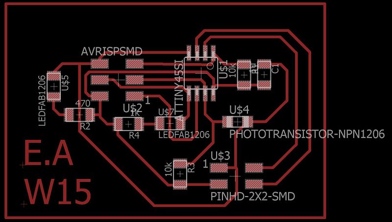
 Finally, we proceed to the creation of the board for its future manufacture.
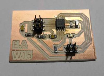
 The result of the manufacture can be seen in the following picture.
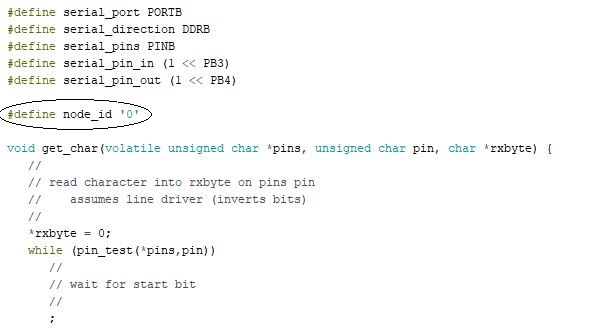
Programming
To understand the serial communication, I charge the example code of Neil, remembering what was explained on Wednesday: we must change the node number for each programmed board, being the 0 in bridge and each board a number, in my case it goes from 0 to 3.
 Once the codes are loaded, we perform the wiring and check its operation, then a video with the operation of the boards.
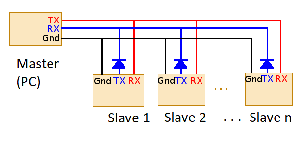
The workflow is simple, the computer works as a master while each board works as a slave, it is the computer that sends the LED activation signal and through the bridge and the FTDI the communication between the computer and the boards is carried out.
It could be configured that one of the boards works as a master and the others are slave, so that the use of the computer would only be a visualization tool but not control.
Interpretation
After carrying out the welding and communication tests, we realize that the master device is our computer, while the nodes are only slaves.This is easy to identify because we send a command through the serial monitor and the others respond to the call. That is why it is important to use an FTDI, otherwise we will not have the means to communicate the PC with the boards.
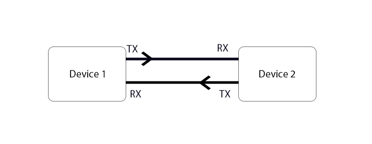
Here is a very basic scheme of the connection of the master / slave.
Groupal
For group work, we must make a communication between the boards of each one, as a personal contribution to the work was created the board with the LDR sensor, in this way you can communicate with the boards of my colleagues.
Next a video of operation of the board.
The code used for this board is as follows.
#include
SoftwareSerial mySerial(3,4);
int valor;
void setup() {
  // put your setup code here, to run once:
  mySerial.begin(9600);
  pinMode(0,OUTPUT);
}

void loop() {
  // put your main code here, to run repeatedly:
  if (mySerial.available() > 0) {
    digitalWrite(0,LOW);
    delay(100);
    digitalWrite(0,HIGH);
    valor = mySerial.read();
  if (valor=='4'){
    mySerial.print("node input, value: ");
     int valor2=analogRead(A1);
  mySerial.println(valor2);
  }
}
} UPDATE
It is very important to interpret the Neil code for this assignment,
because when using the IDE of the Arduino with the programming of the board created with the LDR it gave failures with the communication and the correct sending of information between all the nodes.
After several tests I could not find the fault until the whole code was analyzed in detail.
To get a correct operation we place the pin of the TX initially as an INPUT with the command:input (serial_direction, serial_pin_out), because we are waiting for the input of a signal.
When message is associates with the corresponding node, immediately we must set PORTB of Serial communication to 0, after the pin associated with TX becomes OUTPUT to be able to send a message with the command output (serial_direction, serial_pin_out),
Performs the action corresponding to the message sent and at the end it goes to work again as an INPUT to wait for the new message with input (serial_direction, serial_pin_out), in this way if it can work in a correct way.
From this action will be created some subroutines of high, low and blink of the led, each node will have a different blink.
void high() {
   //
   // LED high
   //
   clear(led_port, led_pin);
 }
void low() {
//
// LED low
//
set(led_port, led_pin);
} void blink() {
//
// LED blink
//
clear(led_port, led_pin);
led_blink(); //#define led_blink() _delay_ms(diferent time)
set(led_port, led_pin);
led_blink();
clear(led_port, led_pin);
led_blink();
set(led_port, led_pin);
led_blink();
} This would serve to be able to separate the electronics of a more complex project, in this way it could be identified in a more efficient way when there would be a failure in the project, Besides being able to create a communication protocol in which each node will know what to do with a message.
Download
You can download this files Here:
Schematic.
Board.
Traces
Out traces.
Code:
LDR Code.
Group code:
LDR Group Code.
LED Group Code.
Update codes:
Node 0.
Node 1.
Node 2.