Week 14: Embedded Networking and Communications
Group Assignment
The objective of the group assignment is to be able to send a message between 2 modules. For this case we have divided the work as follows:
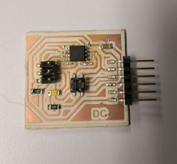
Bridge: Danny
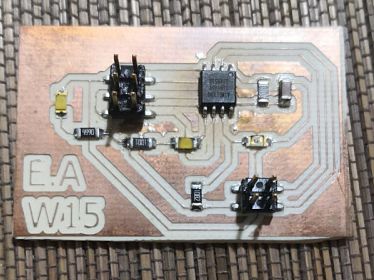
Node input: Edwin
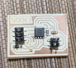
Node ouput: Italo
The communication protocol chosen by all was serial communication, you can see each report individually on their web pages:
Edwin
Danny
Italo
It is important to emphasize that the 3 elements will be programmed with the internal 8mhz clock, otherwise there could be no communication.
This protocol needs to have one master device and another slave. The computer will play the role of teacher to be responsible for sending messages through the serial monitor, others will only perform the actions that arrive through the serial port.
Idea
The boards were programmed in such a way that when sending a 1 for the serial monitor, the led would turn on, if the 2 is pressed it should be turned off of the output node.For the other input node with the LDR, press 3. If the value of the ldr is below 500 in its analog value, the LED should go out and if it exceeds the threshold value it should turn on.
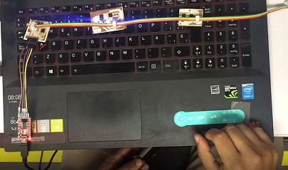
Below is a video of its operation.
Danny's bridge will be in charge of being able to communicate the nodes with the computer using the FTDI, while the others will function as nodes.
In the code we use the statement:
mySerialE.available ()> 0This will be responsible for asking if there is information that reaches the serial port. In the event that the communication condition is met, it will be able to store the information that arrives at the port and perform an action.
Code
The codes used are shown below.
Input
#includeSoftwareSerial mySerialE(3,4); int valor; void setup() { // put your setup code here, to run once: mySerialE.begin(9600); pinMode(0,OUTPUT); } void loop() { // put your main code here, to run repeatedly: if (mySerialE.available() > 0) { //Is information coming? valor = mySerialE.read(); //read the information if (valor=='3'){ mySerialE.print("node input, value: "); int valor2=analogRead(A1); mySerialE.println(valor2); if (valor>500){ digitalWrite(0,HIGH); } else{ digitalWrite(0,LOW); } } } }
Output
It was decided to use the same Neil code for bridge.#includeSoftwareSerial mySerial(3,4); int valor; void setup() { // put your setup code here, to run once: mySerial.begin(9600); pinMode(0,OUTPUT); } void loop() { // put your main code here, to run repeatedly: if (mySerial.available() > 0) { //Is information coming? valor = mySerial.read(); //read the information if (valor=='1'){ digitalWrite(0,LOW); } if (valor=='2'){ digitalWrite(0,HIGH); } } }
//
//
// hello.bus.45.c
//
// 9600 baud serial bus hello-world
//
// Neil Gershenfeld
// 11/24/10
//
// (c) Massachusetts Institute of Technology 2010
// Permission granted for experimental and personal use;
// license for commercial sale available from MIT.
//

#include "avr/io.h>
#include "util/delay.h>
#include "avr/pgmspace.h>
#include "string.h>

#define output(directions,pin) (directions |= pin) // set port direction for output
#define input(directions,pin) (directions &= (~pin)) // set port direction for input
#define set(port,pin) (port |= pin) // set port pin
#define clear(port,pin) (port &= (~pin)) // clear port pin
#define pin_test(pins,pin) (pins & pin) // test for port pin
#define bit_test(byte,bit) (byte & (1 << bit)) // test for bit set
#define bit_delay_time 100 // bit delay for 9600 with overhead
#define bit_delay() _delay_us(bit_delay_time) // RS232 bit delay
#define half_bit_delay() _delay_us(bit_delay_time/2) // RS232 half bit delay
#define led_delay() _delay_ms(100) // LED flash delay

#define led_port PORTB
#define led_direction DDRB
#define led_pin (1 << PB0)

#define serial_port PORTB
#define serial_direction DDRB
#define serial_pins PINB
#define serial_pin_in (1 << PB3)
#define serial_pin_out (1 << PB4)

#define node_id '0'

void get_char(volatile unsigned char *pins, unsigned char pin, char *rxbyte) {
   //
   // read character into rxbyte on pins pin
   //    assumes line driver (inverts bits)
   //
   *rxbyte = 0;
   while (pin_test(*pins,pin))
      //
      // wait for start bit
      //
      ;
   //
   // delay to middle of first data bit
   //
   half_bit_delay();
   bit_delay();
   //
   // unrolled loop to read data bits
   //
   if pin_test(*pins,pin)
      *rxbyte |= (1 << 0);
   else
      *rxbyte |= (0 << 0);
   bit_delay();
   if pin_test(*pins,pin)
      *rxbyte |= (1 << 1);
   else
      *rxbyte |= (0 << 1);
   bit_delay();
   if pin_test(*pins,pin)
      *rxbyte |= (1 << 2);
   else
      *rxbyte |= (0 << 2);
   bit_delay();
   if pin_test(*pins,pin)
      *rxbyte |= (1 << 3);
   else
      *rxbyte |= (0 << 3);
   bit_delay();
   if pin_test(*pins,pin)
      *rxbyte |= (1 << 4);
   else
      *rxbyte |= (0 << 4);
   bit_delay();
   if pin_test(*pins,pin)
      *rxbyte |= (1 << 5);
   else
      *rxbyte |= (0 << 5);
   bit_delay();
   if pin_test(*pins,pin)
      *rxbyte |= (1 << 6);
   else
      *rxbyte |= (0 << 6);
   bit_delay();
   if pin_test(*pins,pin)
      *rxbyte |= (1 << 7);
   else
      *rxbyte |= (0 << 7);
   //
   // wait for stop bit
   //
   bit_delay();
   half_bit_delay();
   }

void put_char(volatile unsigned char *port, unsigned char pin, char txchar) {
   //
   // send character in txchar on port pin
   //    assumes line driver (inverts bits)
   //
   // start bit
   //
   clear(*port,pin);
   bit_delay();
   //
   // unrolled loop to write data bits
   //
   if bit_test(txchar,0)
      set(*port,pin);
   else
      clear(*port,pin);
   bit_delay();
   if bit_test(txchar,1)
      set(*port,pin);
   else
      clear(*port,pin);
   bit_delay();
   if bit_test(txchar,2)
      set(*port,pin);
   else
      clear(*port,pin);
   bit_delay();
   if bit_test(txchar,3)
      set(*port,pin);
   else
      clear(*port,pin);
   bit_delay();
   if bit_test(txchar,4)
      set(*port,pin);
   else
      clear(*port,pin);
   bit_delay();
   if bit_test(txchar,5)
      set(*port,pin);
   else
      clear(*port,pin);
   bit_delay();
   if bit_test(txchar,6)
      set(*port,pin);
   else
      clear(*port,pin);
   bit_delay();
   if bit_test(txchar,7)
      set(*port,pin);
   else
      clear(*port,pin);
   bit_delay();
   //
   // stop bit
   //
   set(*port,pin);
   bit_delay();
   //
   // char delay
   //
   bit_delay();
   }

void put_string(volatile unsigned char *port, unsigned char pin, PGM_P str) {
   //
   // send character in txchar on port pin
   //    assumes line driver (inverts bits)
   //
   static char chr;
   static int index;
   index = 0;
   do {
      chr = pgm_read_byte(&(str[index]));
      put_char(&serial_port, serial_pin_out, chr);
      ++index;
      } while (chr != 0);
   }

void flash() {
   //
   // LED flash delay
   //
   clear(led_port, led_pin);
   led_delay();
   set(led_port, led_pin);
   }

int main(void) {
   //
   // main
   //
   static char chr;
   //
   // set clock divider to /1
   //
   CLKPR = (1 << CLKPCE);
   CLKPR = (0 << CLKPS3) | (0 << CLKPS2) | (0 << CLKPS1) | (0 << CLKPS0);
   //
   // initialize output pins
   //
   set(serial_port, serial_pin_out);
   input(serial_direction, serial_pin_out);
   set(led_port, led_pin);
   output(led_direction, led_pin);
   //
   // main loop
   //
   while (1) {
      get_char(&serial_pins, serial_pin_in, &chr);
      flash();
      if (chr == node_id) {
         output(serial_direction, serial_pin_out);
         static const char message[] PROGMEM = "node ";
         put_string(&serial_port, serial_pin_out, (PGM_P) message);
         put_char(&serial_port, serial_pin_out, chr);
         put_char(&serial_port, serial_pin_out, 10); // new line
         led_delay();
         flash();
         input(serial_direction, serial_pin_out);
         }
      }
   }
Problems
We wanted to show on the serial monitor the name of the node and indicate its value in the case of the LDR and if the led is on or not, the inconvenience was that the messages could never be shown.Investigating a bit we reached the conclusion of the incompatibility of the code of the bridge with the nodes, that is why only the action of the led was chosen depending on the input value of the sensor and the serial communication.
Download
You can download the files here.Bridge -ino
LDR -ino
LED -ino