Week 14: Networking and Communications
For this week, we demonstrate workflows used in network design, also implement and interpret networking protocols
Individual assignment
This week I chose to make the example of serial bus communication, in my case I will use the FTDI to communicate the laptop (master) to the nodes (slaves) through a bridge. Also, I used a 4-socket cable to connect the nodes and the bridge.
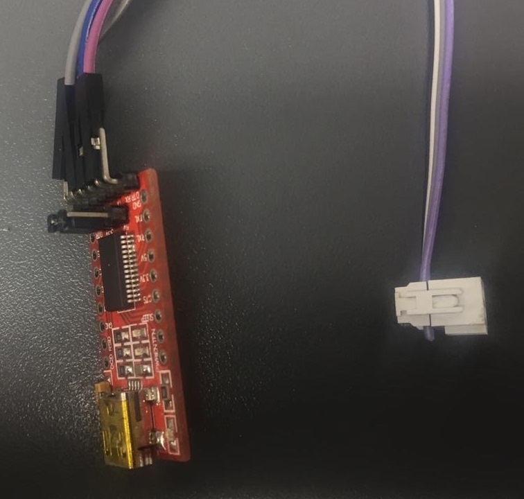 Fig.01 - FTDI
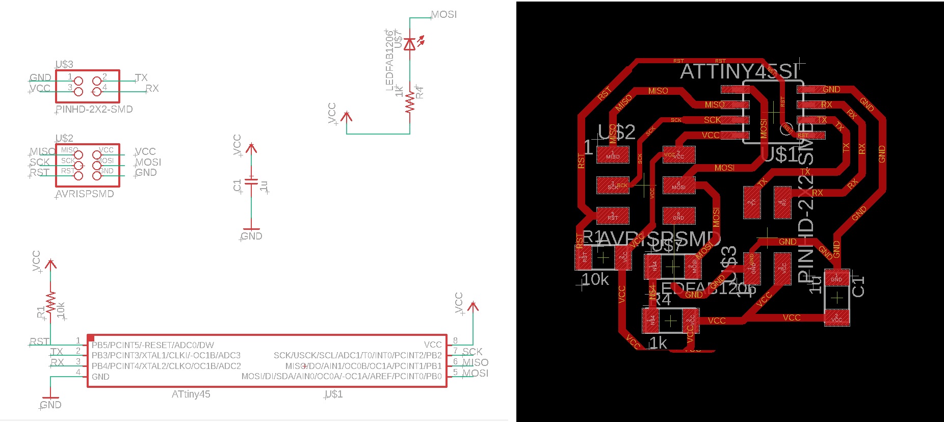
 I used the Neil boards and designed my bridge version using the Eagle software. This board has a 3x2 socket to burn the boot loader. It was a little tedious to join the capacitor but in the end it was achieved, the size of the lane decreased.
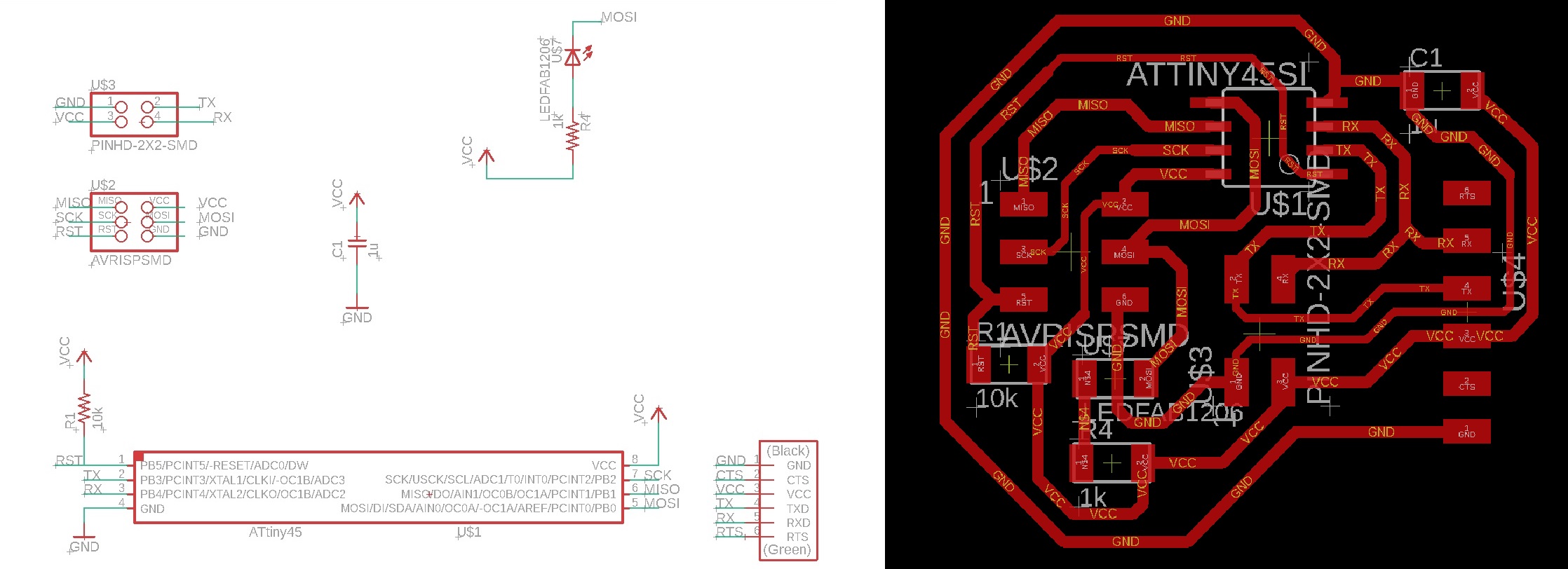 Download Bridge
 Fig.02 - Bridge
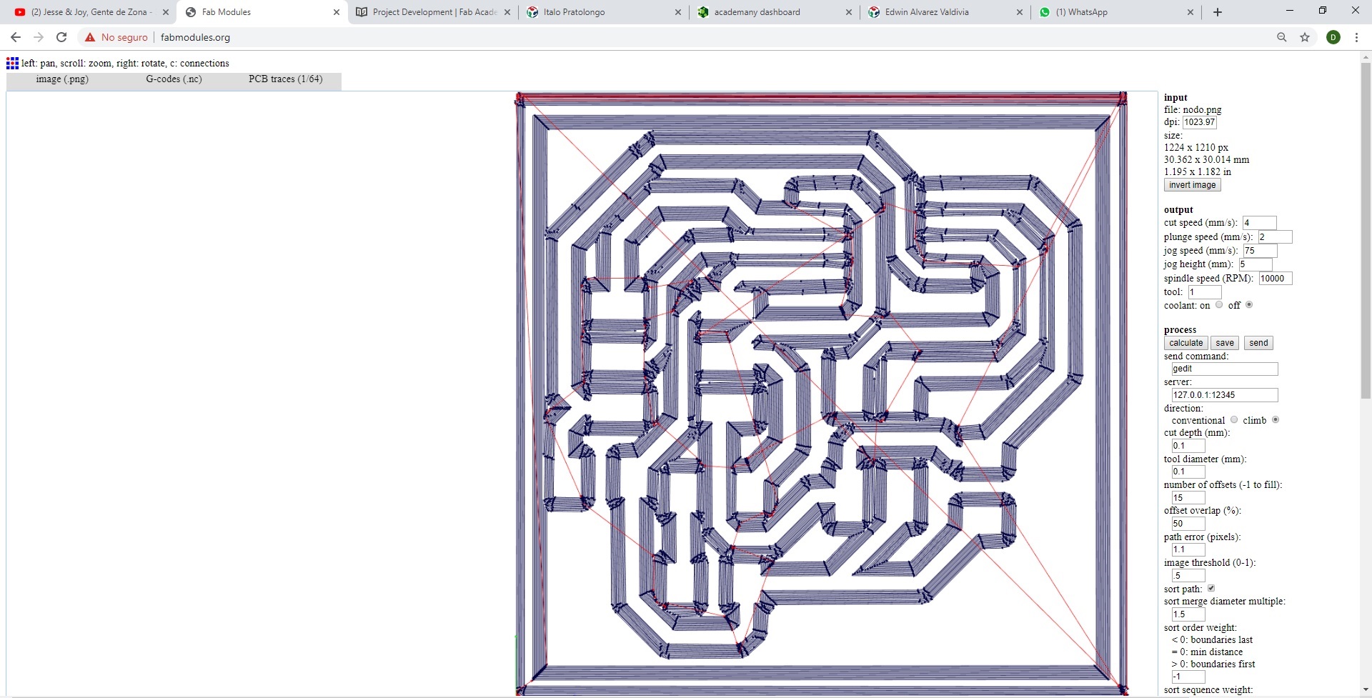
Once the file was exported in PNG format, we inserted the design of the bridge into the fabmodules page. The cutting parameters in the CNC machine are the following: tool diameter (0.1mm), number off offsets (15) and spindle speed (8000 RPM).
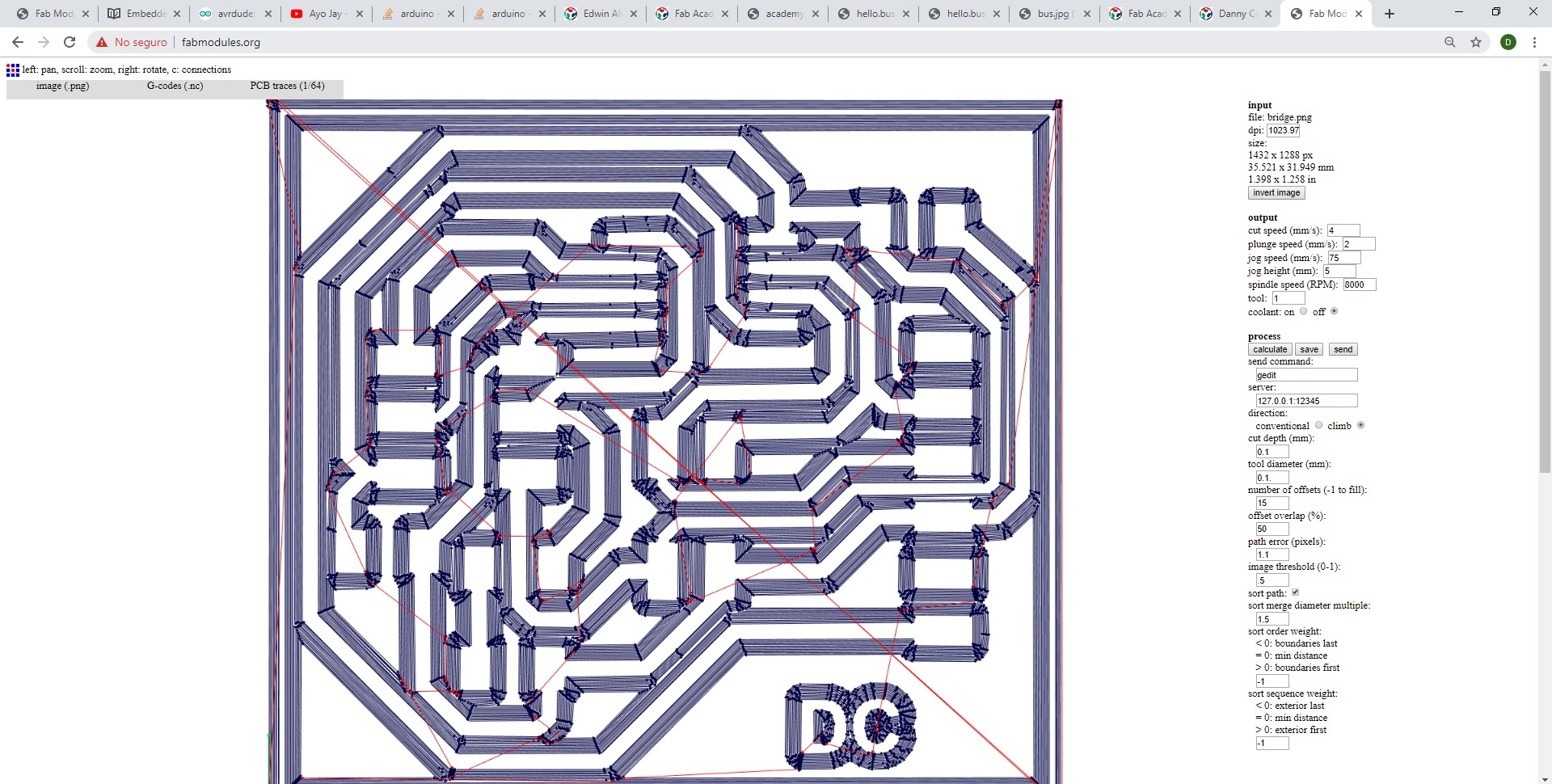 Download Bridge PNG
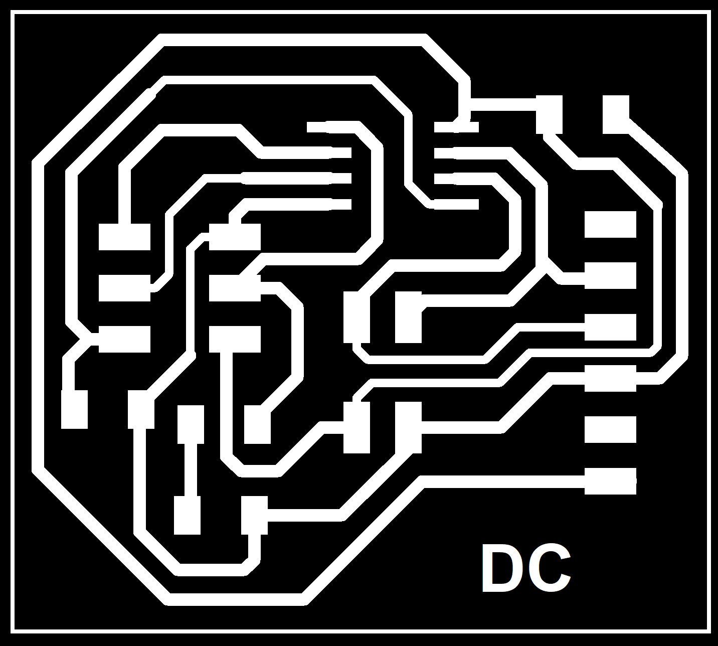
Download Bridge G-Code
Fig.03 - Bridge
It was verified that the rails are complete and went through to weld the design with solder. Upon completion, continuity was checked to avoid problems when burning the board.
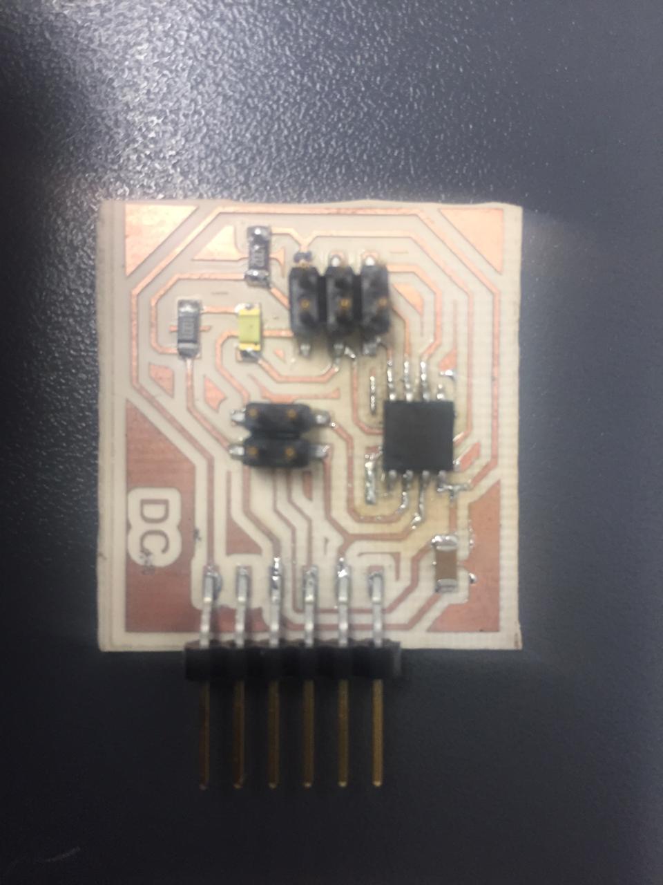 Fig.04 - Bridge
 I used the Neil boards and designed my version of nodes, in this opportunity I removed the FTDI entries. Each board has a 3x2 socket to burn the boot loader.
 Download Node
 Fig.05 - Node
Once the file was exported in PNG format, we inserted the bridge design into the fabmodules page. The cutting parameters in the CNC machine are the following: tool diameter (0.1mm), number off offsets (15) and spindle speed (8000 RPM).
 Download Nodo PNG
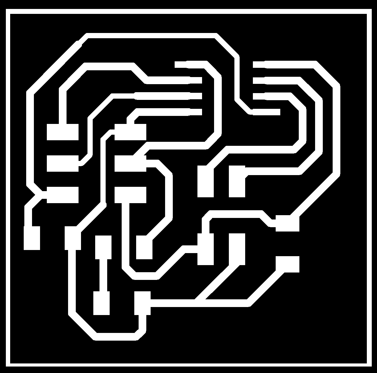
Download Nodo G-Code
Fig.06 - Node
It was verified that the rails are complete and went through to weld the design with solder. Upon completion, continuity was checked to avoid problems when burning the board. One of them was not connected for lack of welding, adding a little weld on the pins solved the problem.
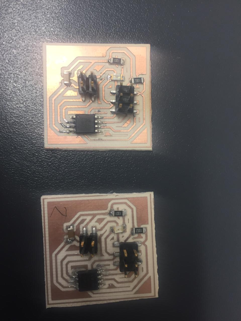 Fig.07 - Nodes
 At the end of welding the boards, one went to burn one by one the bridge boards and the two nodes. With the help of the ISP, the bootloader was burned.
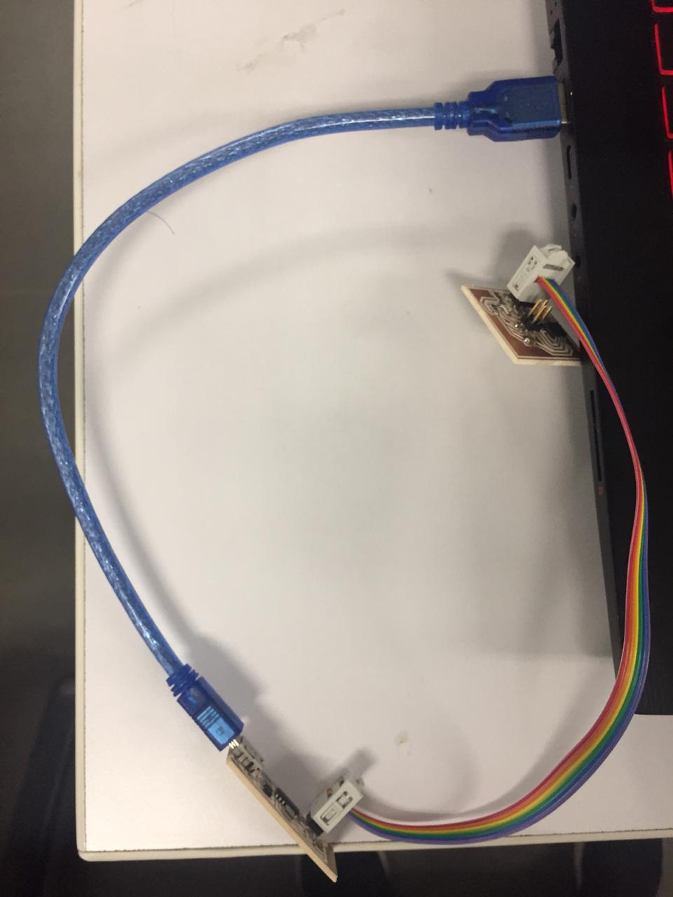 Fig.08 - ISP
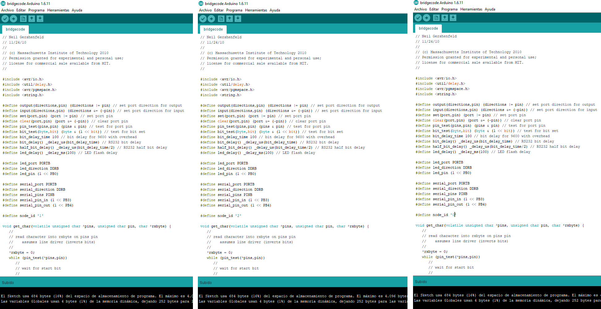
 Once the bootloader was burned, Neil's code was added hello.bus.45.c in the arduino program and it was uploaded using the ISP programmer.
 Download Code
 Fig.09 - Upload Code
We connect the bridge to the PC and through the 2x2 data cables we connect the nodes. We test the communication by writing "node #" with the number that we want to activate and this will be observed when the LED lights up
Update
To get a correct operation we place the pin of the TX initially as an INPUT with the command:input (serial_direction, serial_pin_out), because we are waiting for the input of a signal. When message is associates with the corresponding node, immediately we must set PORTB of Serial communication to 0, after the pin associated with TX becomes OUTPUT to be able to send a message with the command output (serial_direction, serial_pin_out), Performs the action corresponding to the message sent and at the end it goes to work again as an INPUT to wait for the new message with input (serial_direction, serial_pin_out), in this way if it can work in a correct way.
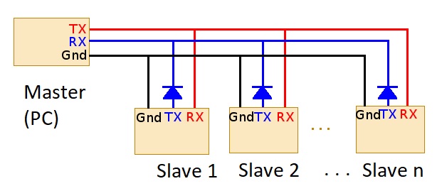 Fig.11 - Master
 I will modify the Neil code to be able to perform new functions and connect them in a network to form a system. For this I will use the board ATmega328 that i designed in the week of interface & aplication programming. The serial pin in / out were added and new "ID" nodes will be defined to establish new functions.
I will use a board that I found in the CIT laboratory, to show the functions of the LED
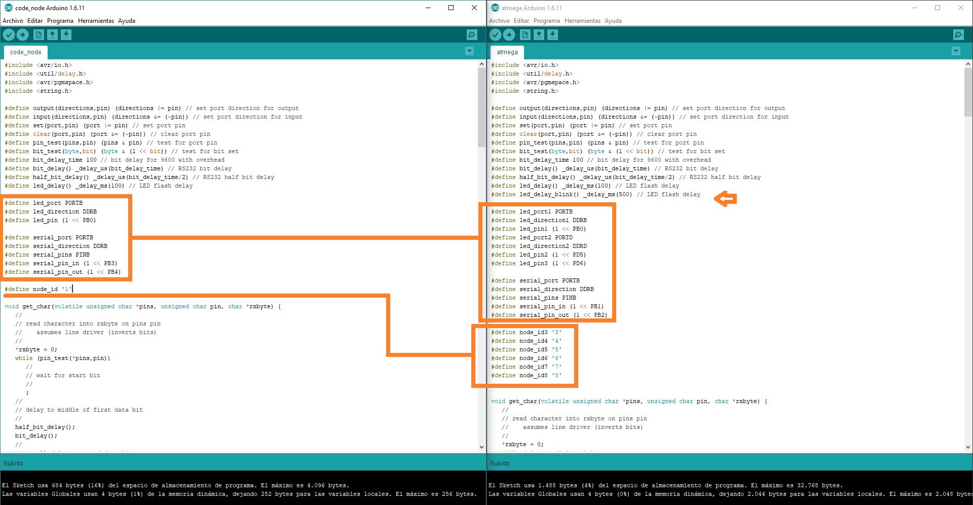 Fig.12 - Definde LED, Port & Pins
 In the part of the flash void, we establish the functions of each node. For example we want flash3 to establish a connection, produce a delay and again cut the signal with the definition of "clear". In this way we declare the functions we want to perform.
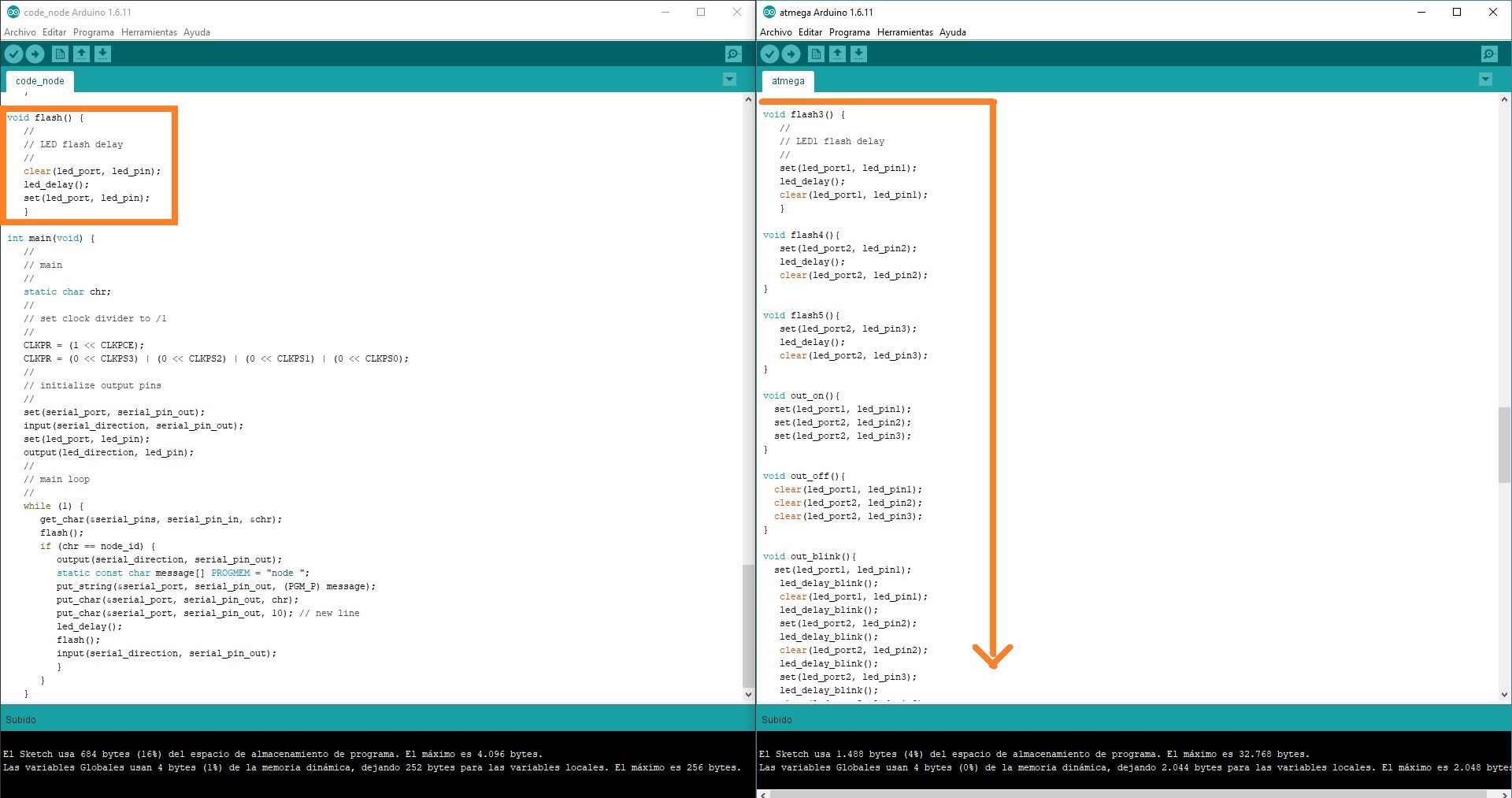 Fig.13 - Void Flash
 Finally, we go to "get_char", here we declare the names, the PROGMEM and the variable that we want to observe when opening the serial monitor.
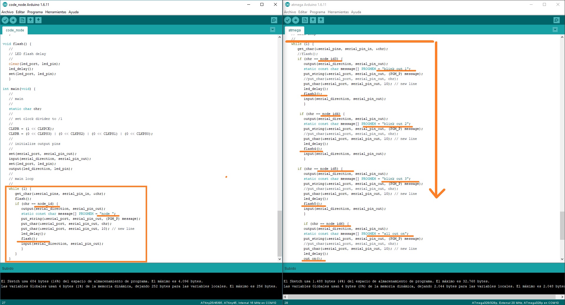 Fig.14 - While / Get Char
 If we follow the correct steps, we will achieve new functions and we can connect them in a network to form a new system. In the video it is shown the declared data when pressing the keys 3,4,5,6,7,8 will be shown in the serial monitor: flash3, flash4, flash5, out_on, out_off and out_blink.