Week 5: Electronics Production
This week I will make a system programmer for AVR microcontrollers, for this I will mill a FabISP plate and then solder its components.
Individual assignment
Milling the FabISP
I started by downloading Eagle from the autodesk website . This is a program for designing diagrams and PCBs with auto-router. In my case I will use the windows version.
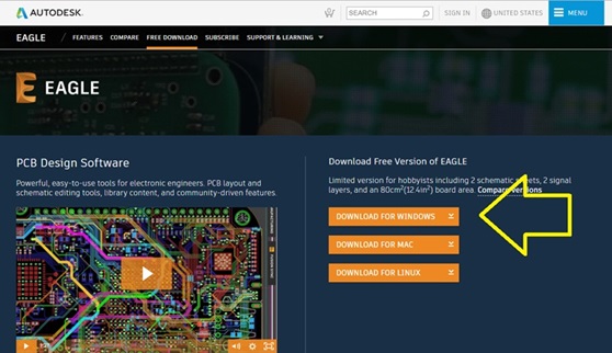 Fig.01 - Eagle Download
 The Eagle interface presents a tutorial for newbies and some updates. I was reviewing how to draw, import and export files..
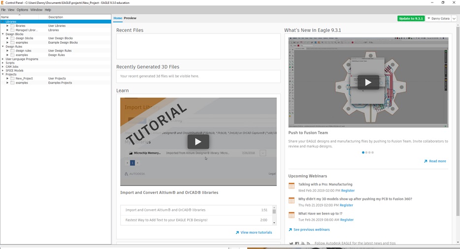 Fig.02 - Eagle Interface
 I will use the ATtiny44 microcontroller Ali, since it explains the purpose of each component and how the FabISP board design works. In the laboratory we have 1K resistors and 0.5K resistors. Therefore, I will use the version R_pullup is 1K + 0.5K.
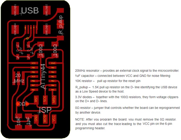 Fig.03 - ATtiny44/ Ali
 I downloaded the schematic board and the board layout, to understand how the workflow is when using the Eagle program.
I understood that in the schematic we can detect errors before the board is made and on the board we can design our tastes.
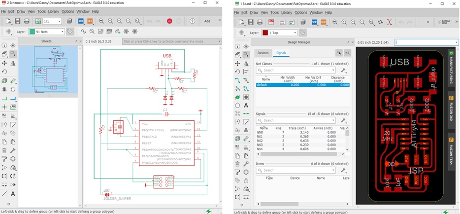 Download (R_pullup=1K+0.5K) SCH & BRD
 Fig.04 - Eagle SCH & BRD
As a first step for milling, we need the image in .png format, then we access the website Fab modules to generate parameters for the Roland Modella machine. In the input format we select the image in .png, then for output format the g-code and finally for the traces the process PCB (1/64).
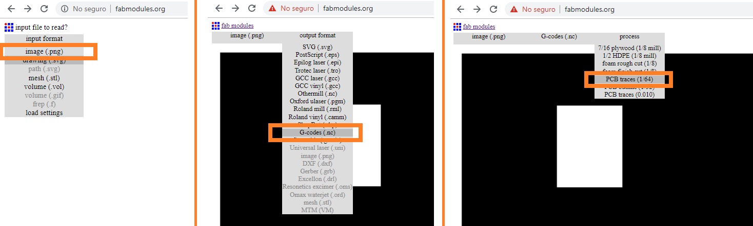
Download PNG
Fig.05 - Fab modules Interface
The result is an alphanumeric code that represents the route and the cut that will be developed on the plate. The amount of number of offsets will give us a better separation between courses, this will avoid, in the soldering process, that excess flux will not mix with the tracks.
For this we modify some parameters like the following: 8000 spindle speed (RPM), coolant off, 01mm tool diameter and 20 number of offsets. We save the file and a file with an .nc extension is generated.
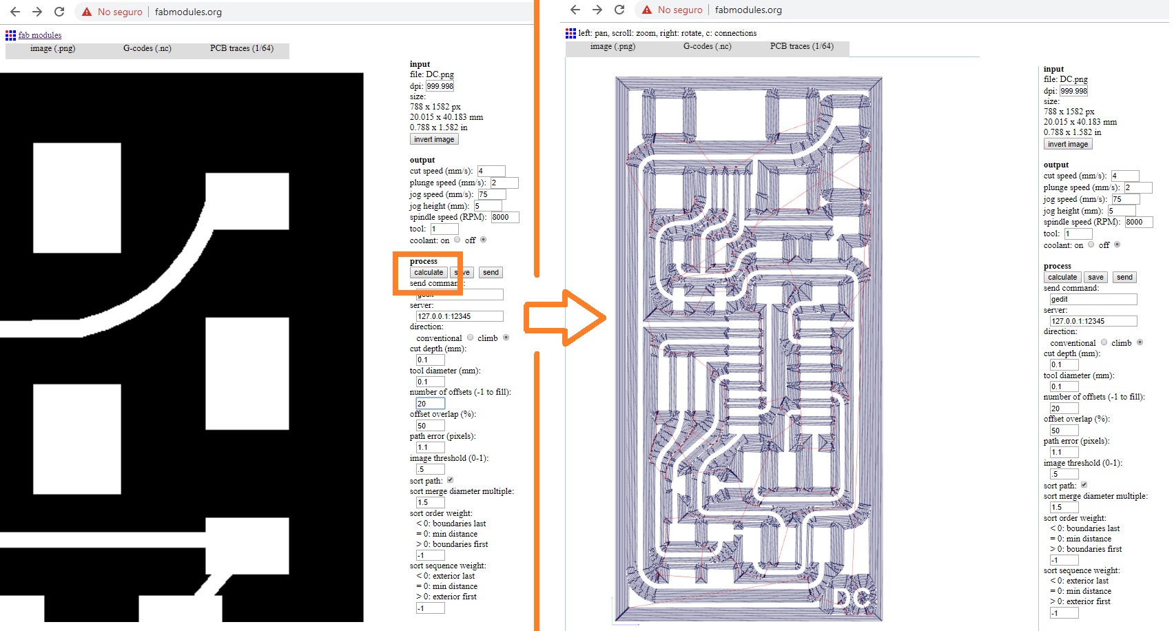
Download G-Code
Fig.06 - G-Code
For the manufacture of the PCB in the laboratory of FAB LAB CIT ULIMA we will find the Roland Modella MDX-540.
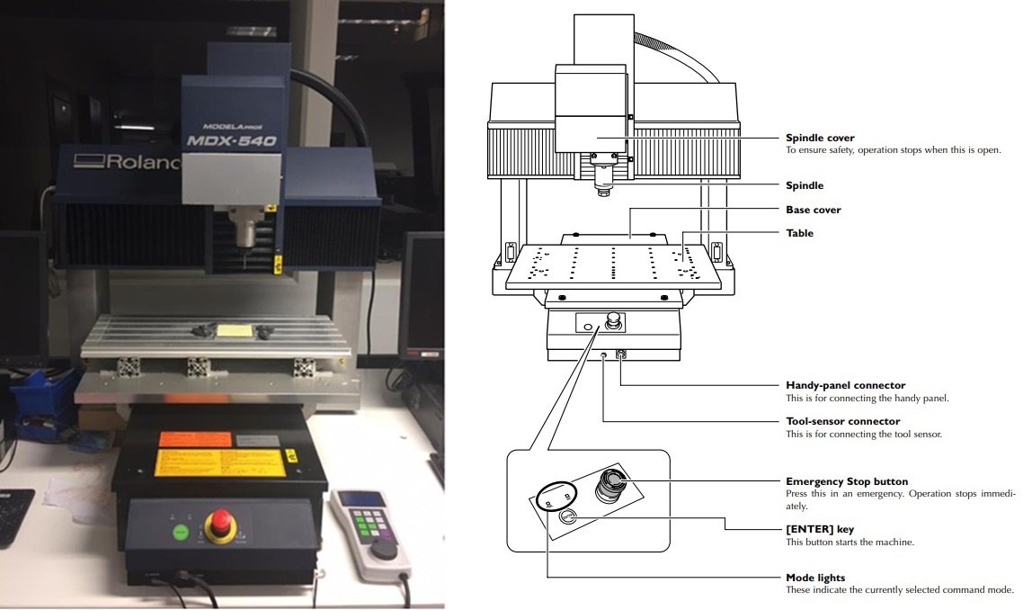 Fig.07 - Roland MDX-540
 I will show elements and their functions that make up the CNC. It is very important to understand some connections to perform a good maintenance or avoid an accident in case of emergency.
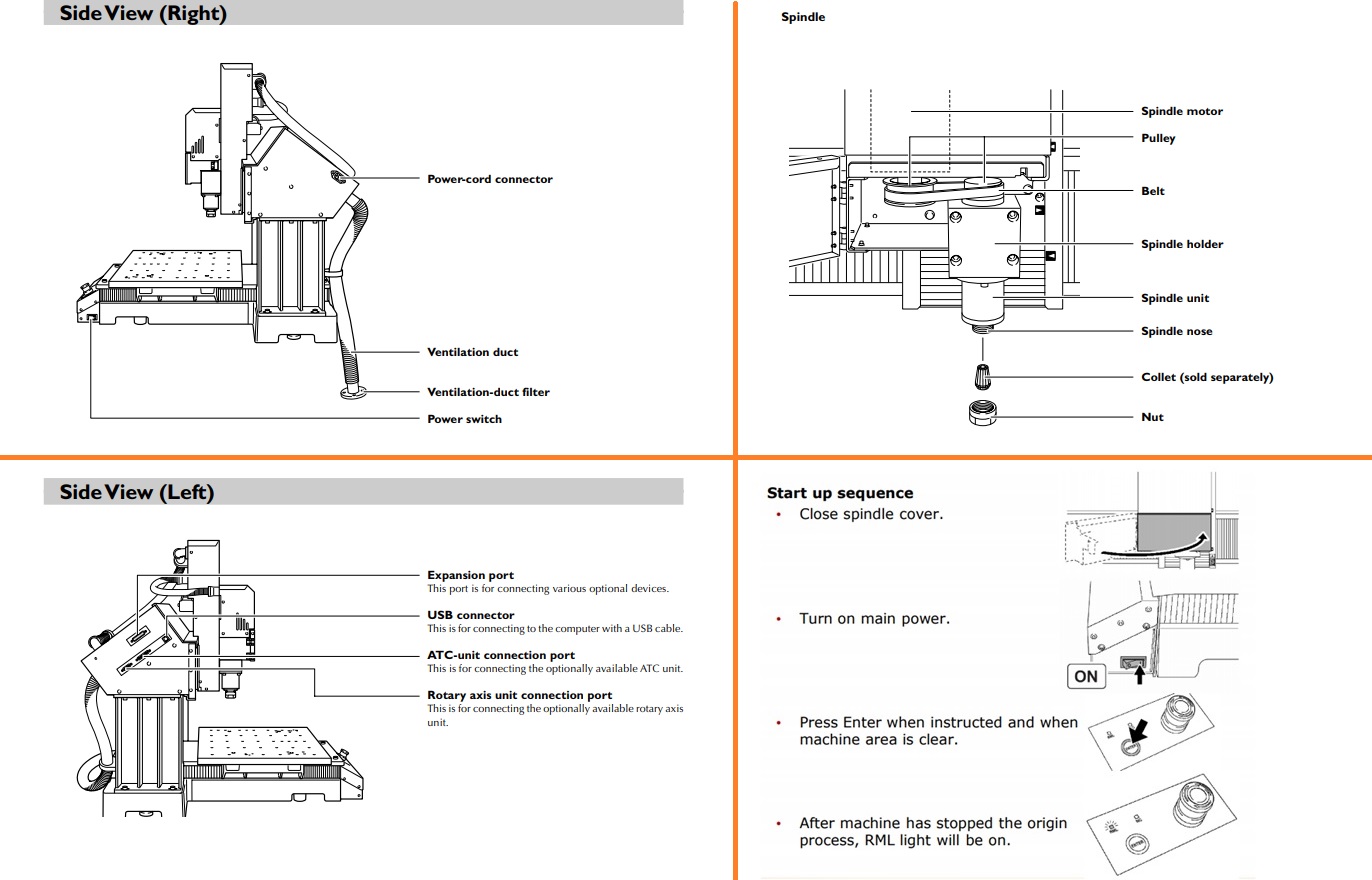 Fig.08 - MDX-540 Elements
 You can also use the handy panel to control the machine. The handy panel brings together a number of frequently used features.
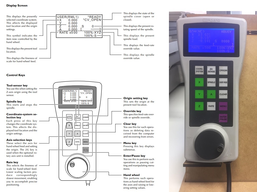 Fig.09 - Handy Panel
 The milling cutters are engraving tools used in CNC machines and pantographs. In the fablab CIT, there are milling cutters of widia lip, flat lips, two lips, compression, grinding, spherical and conical
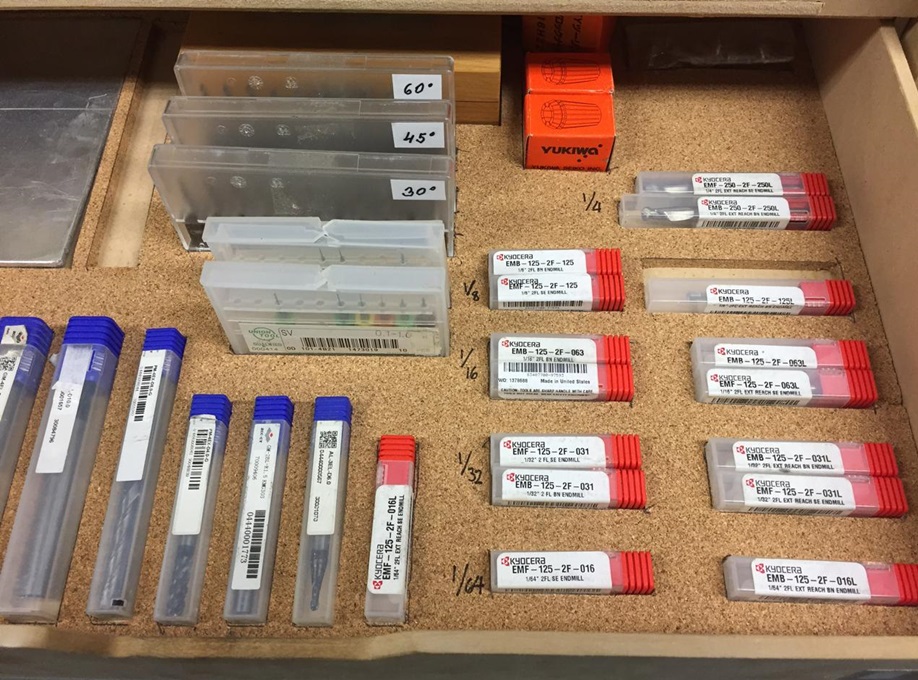 Fig.10 - Milling cutters
 To change the accessories of the MDX-540 milling machine, it is sufficient to pull the metal cover and unscrew the gears. To remove collet, remove nut and tip collet sideways to loosen.
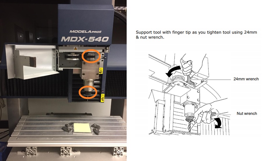 Fig.11 - Change of milling tools
 To place the zero position on the board, we use the handy panel. By placing the zero point on the X-axis and the Y-axis, we precede origin.
Place the tool sensor on the top surface of the workpiece where you want to set the Z-axis origin. Move the tool to the area above the sensor.
The software of Roland Modella MDX-540 looks like this, in this we can configure the speed and the positions of the axes x-y-z, the base point, the move tool and some preferences.
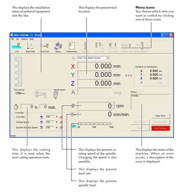 Fig.13 - Software of Roland MDX-540
 To insert the G-Code, it is necessary to click on the CUT tool, this will open a window in which the file can be dragged and we will be ready to send it to cut.
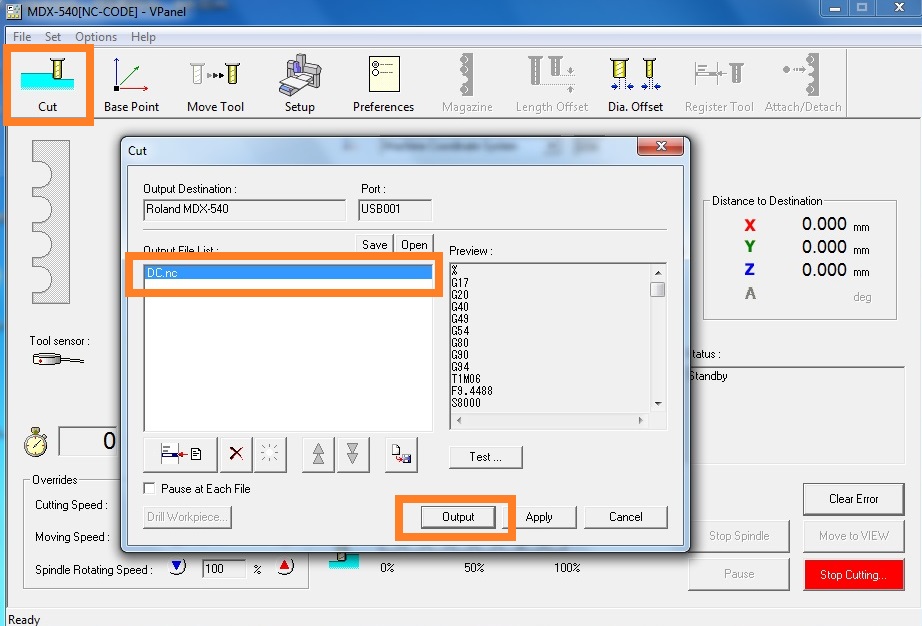 Fig.14 - MDX-540 Output File
 After clicking on the output button of the Roland Modela software mdx-540, it will start generating the routes.
The routes were complete and I checked the continuity with the multimeter.
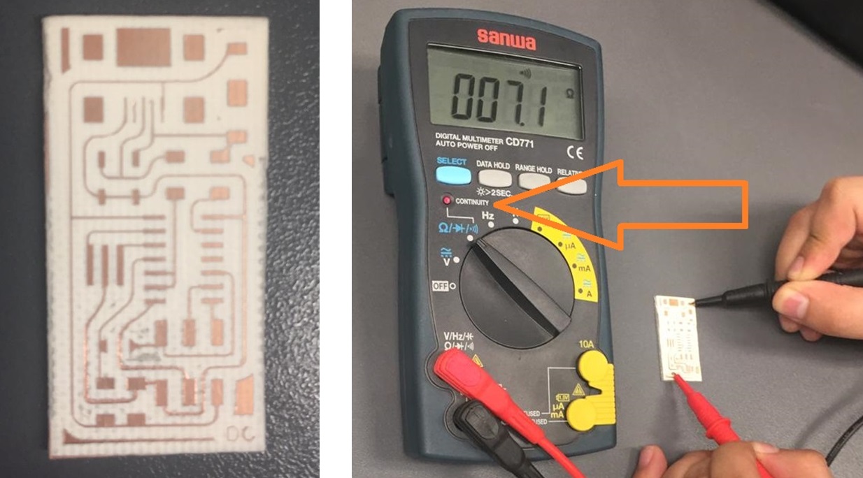 Fig.16 - Routes
 PCB ceramic and flux were used. The flux should be applied in ventilated places. It is advisable to wear glasses, mask and protective gloves during handling. I find the components for this activity in the CIT laboratory.
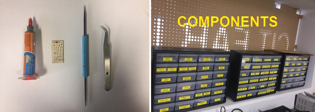 Fig.17 - Solder Tools
 At the beginning it was difficult to place the necessary amount of flux on the plate, but with the practice I managed to solder all the components. We must take into account some recommendations before programming, first we must review continuity between the components. The mistake I made was to cut with a blade the board and not to do it with the machine, when I interacted one of the Attiny44 pins got desoldered. The solution was to cover the damaged part with flux and the ISP went back to work.
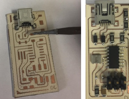 Fig.18 - ISP Board
 Programming
For the programming of the ISP, a laptop with the Ubuntu software was used. We use a tutorial FabISP Programming. The software was installed using the following commands.
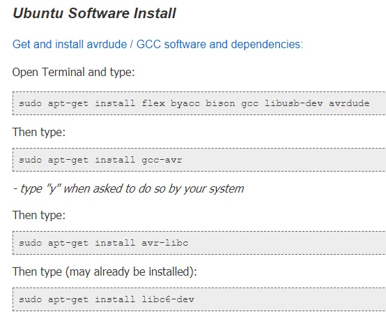 Fig.19 - Ubuntu Software Install
 I create a folder on the desktop and download the requested firmware.
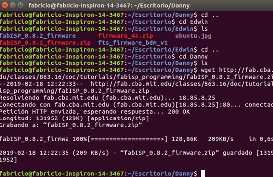 Fig.20 - Download the Firmware
 Unzip the firmware
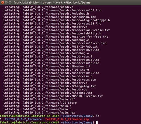 Fig.21 - Unzip the Firmware
 The next step is to connect my ISP to the computer with the help of another ISP programmer, in this case I used the USB AVARIPS XPII.
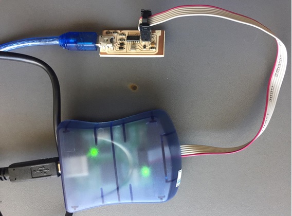 Fig.22 - USB AVARIPS XPI & ISP
 Once connected and seeing that everything is correct, navigate to the directory where you saved the FabISP firmware. If you followed the instructions above, this will be the desktop.
Type "make clean", then "make hex", "make fuse" and finally "make program". If you are successful, you will see the following response from the system.
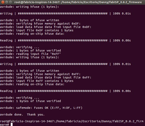 Fig.23 - Response from the System
 Hero Shot
This is my FabISP.
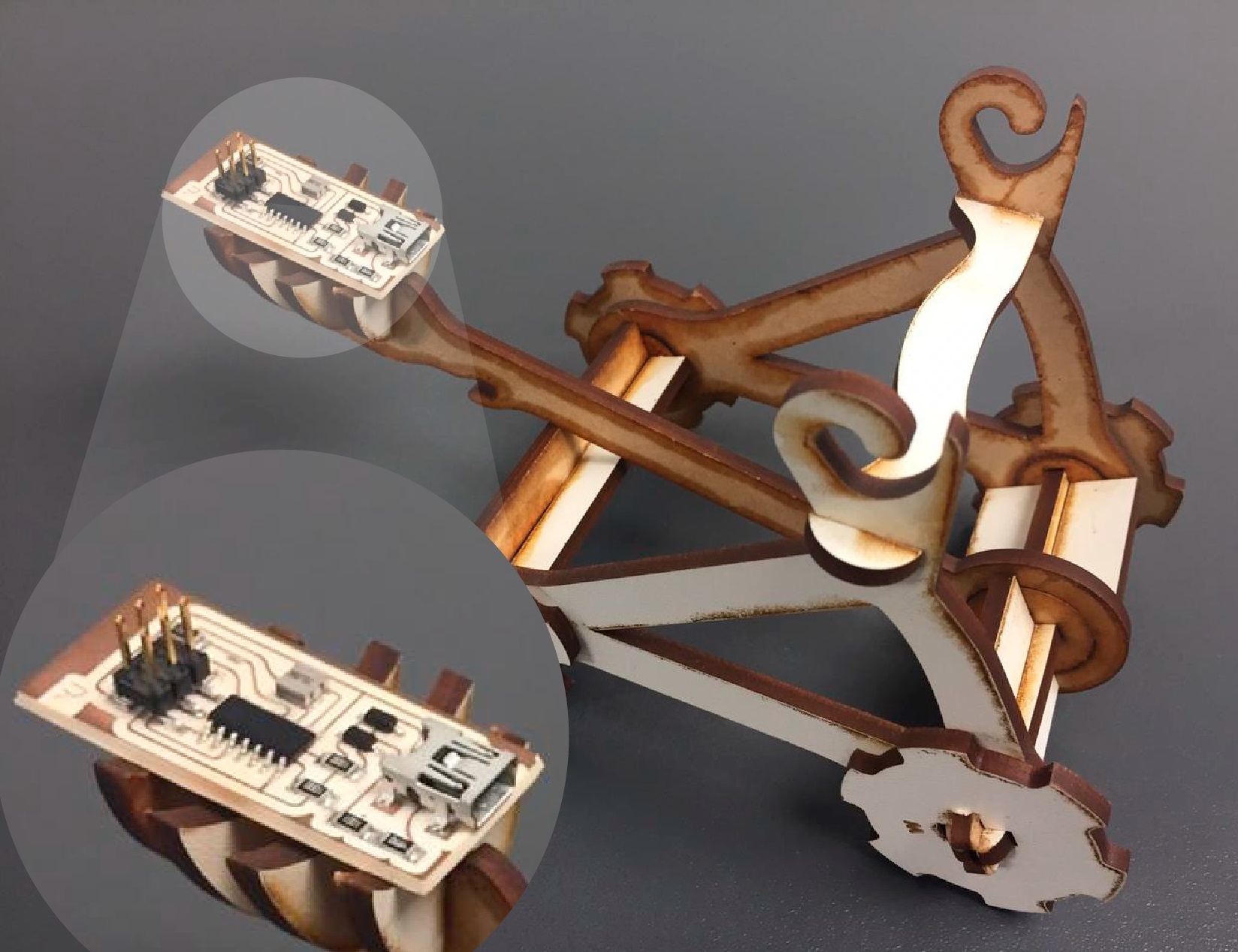 Fig.24 - Hero shot
 Group assignment
In group work, mechanized test lines were made in ceramic PCB and fiberglass materials. The milling machines were 1/64 and 1/45. The image was exported in PNG format and worked on the fabmodules page. The parameters were changed as the spindle speed to 8000 RPM, the tool diameter to 01mm and a number of offsets of 15.
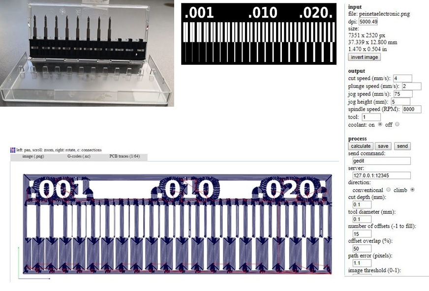 Fig.25 - Tools & Fabmodules
 In group work, mechanized test lines were made in ceramic PCB and fiberglass materials. The milling machines were 1/64 and 1/45.
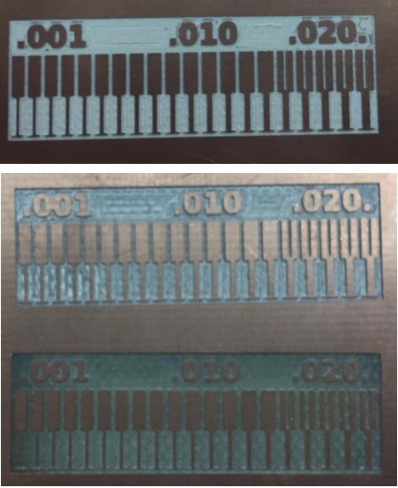 Fig.26 - Group Board
 To see all the documentation of the group work, you can visit the CIT page.