experimentation
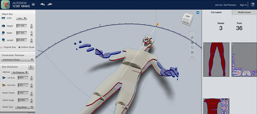
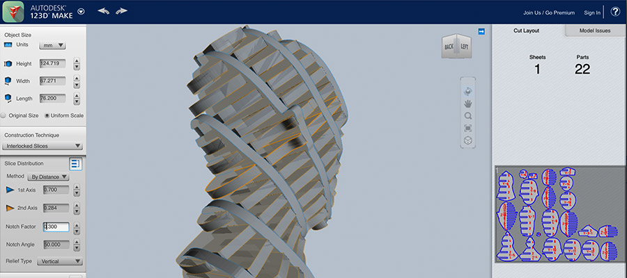
Aim to use the computer-controlled cutting technique related to the topic of my final project I decided to use commercial software to create first - human body, head piece and than mesh to unfold/make waffle structure and than cut and engrave with laser cutting machine. see the process under. workflow in Make Human, Rhinoceros 3D and 123D Make - free open source software that generates unfolded patterns from 3D data
Group assignment
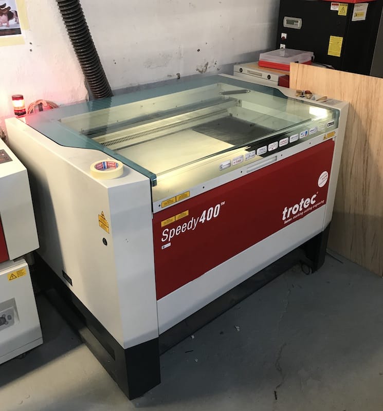
Out of the 3 machines Fab Lab Barcelona have, we choose to use the Trotec Speedy400. It is a machine with following specs: 1000x610mm 100W_Trotec Speedy400
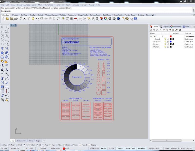
The jobs run from a computer next to it, through Rhinoceros, print driver and controller. The software is basically used for importing files and assigning colors and layers. This step is important specially if you are going to work with more than one work operation.
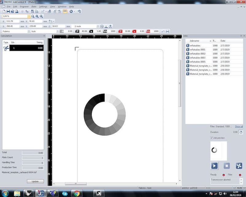
After setting the layers and sending the print command, the job goes to the controller.
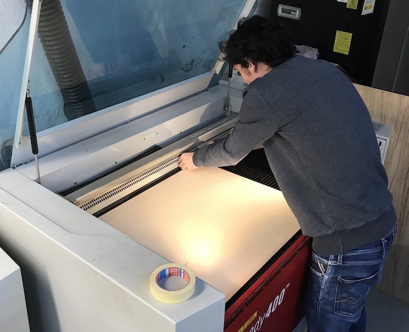
Putting the material to the machine.
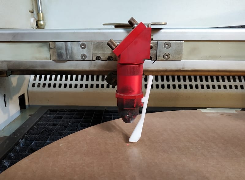
Focus the machine - level up the platform and setup the right distance between the laser lense and the material using special distance measure tool.
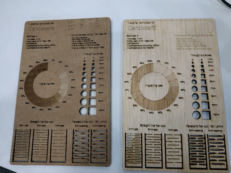
Now the machine and material is ready to test. We used cardboard and plywood for our tests.
Settings used:
Cut: 4mm Cardboard: 50 Power, 1 Speed, 1000 PPI 4mm Plywood: 75 Power, 0,8 Speed, 1000 PPI
Engrave: 4mm Cardboard: 30 Power, 100 Speed, 1000 PPI 4mm Plywood: 60 Power, 100 Speed, 1000 PPI
Raster: 4mm Cardboard: 80 Power, 100 Speed, 1000 PPI 4mm Plywood: 60 Power, 100 Speed, 1000 PPI
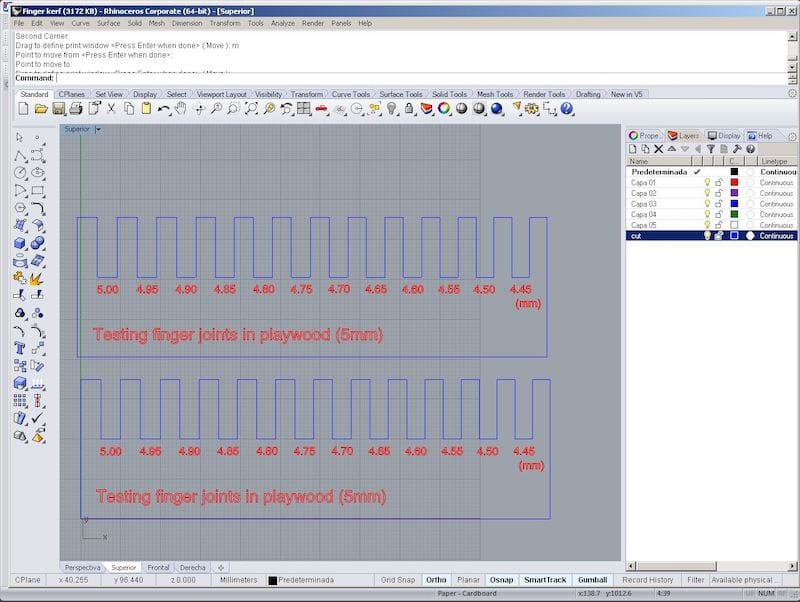
After getting the right settings for the materials, we went to test the press kits
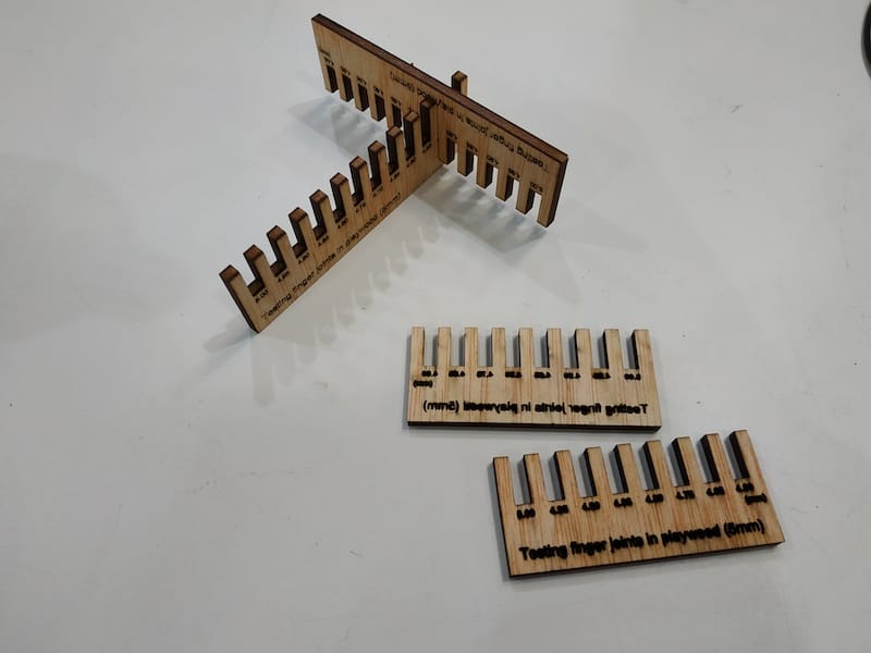
The best results were 3.85mm and 3.35mm gaps for plywood and cardboard respectively. This big difference between the two comes from two reasons:
1. The cardboard had a bigger kerf. Maybe just because the material burns more easily. But we believe it may come from laser being over powered
2. Cardboard squeezes way more than plywood. Fitting in tighter gaps
Individual assignment
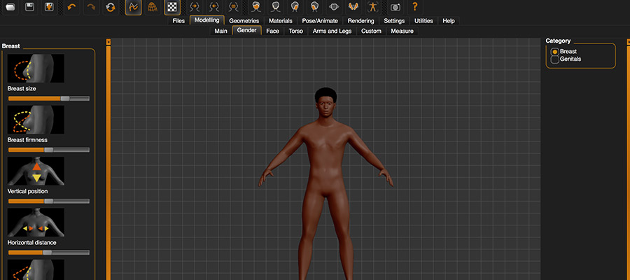
MakeHuman
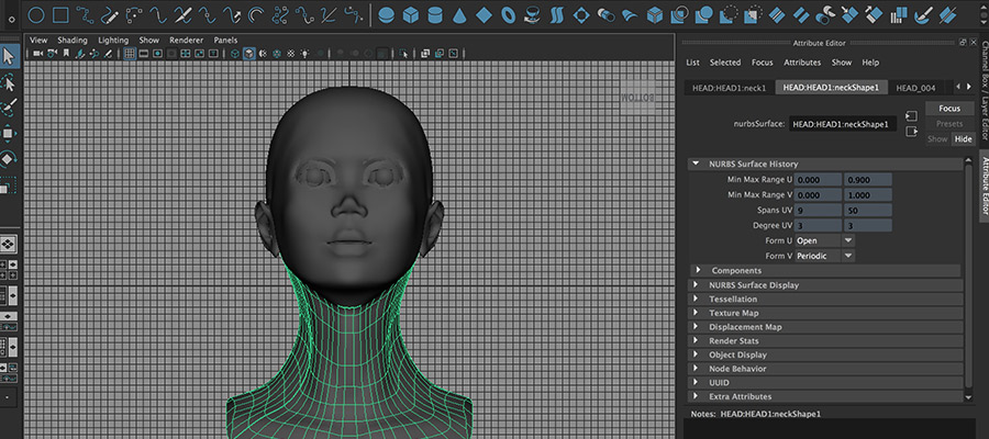
Maya
123D Make
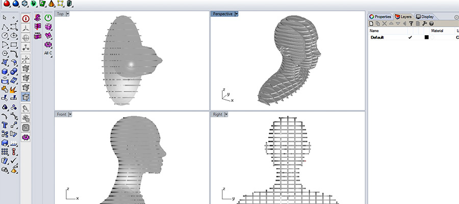
Rhinoceros 3D
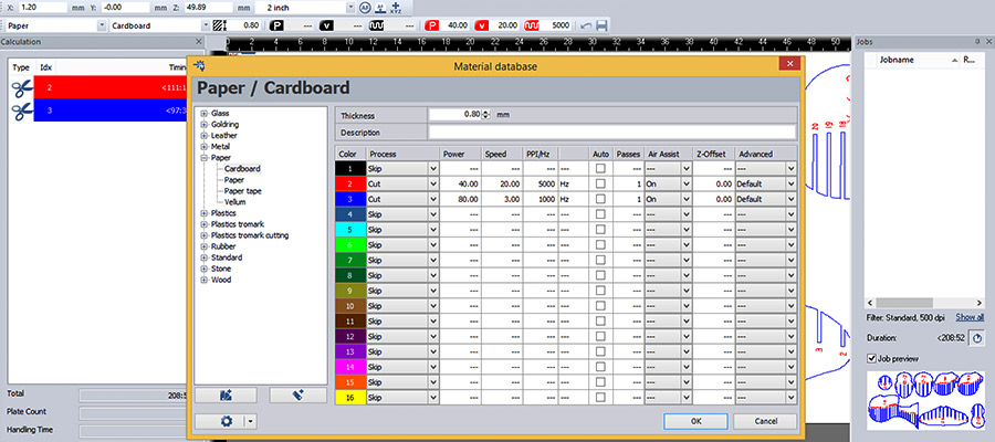
Trotec_JobControl

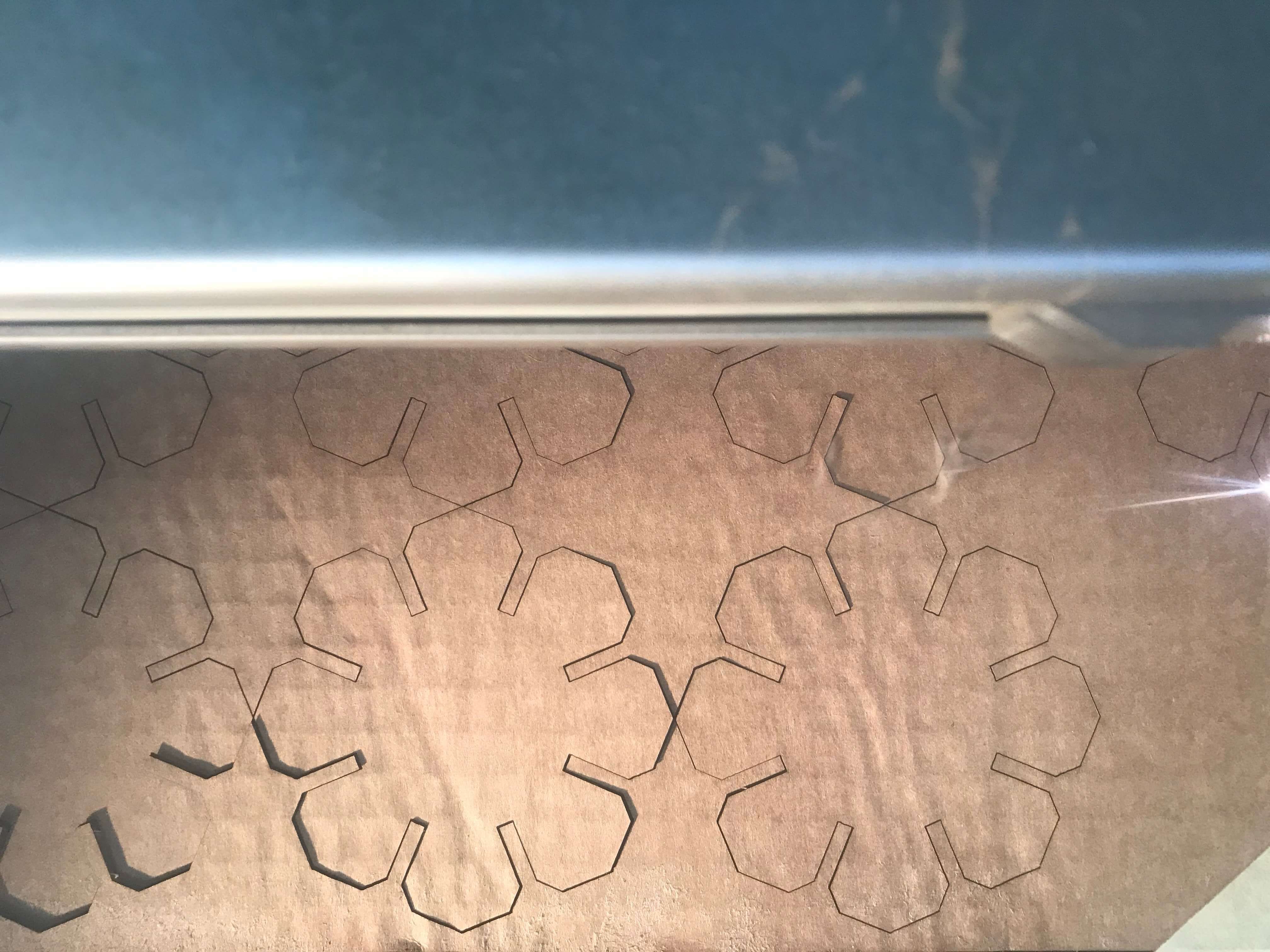
Laser Cutting
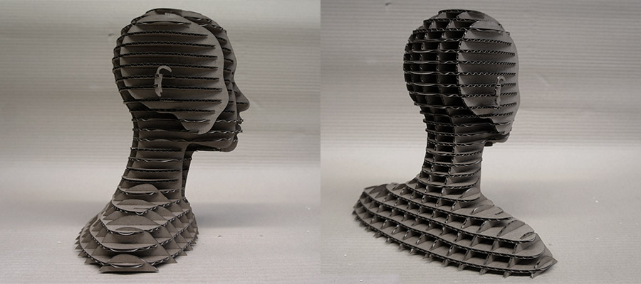
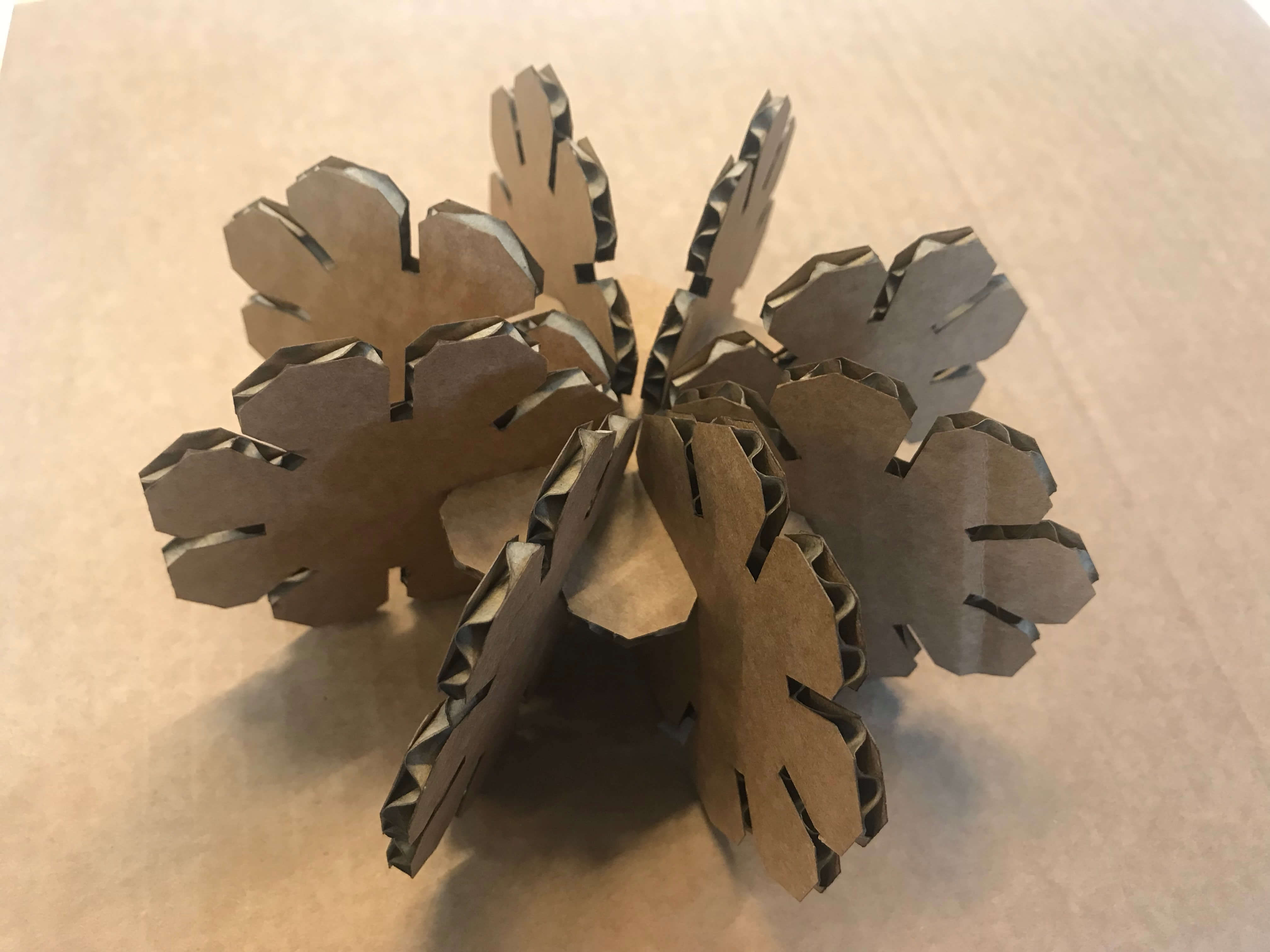
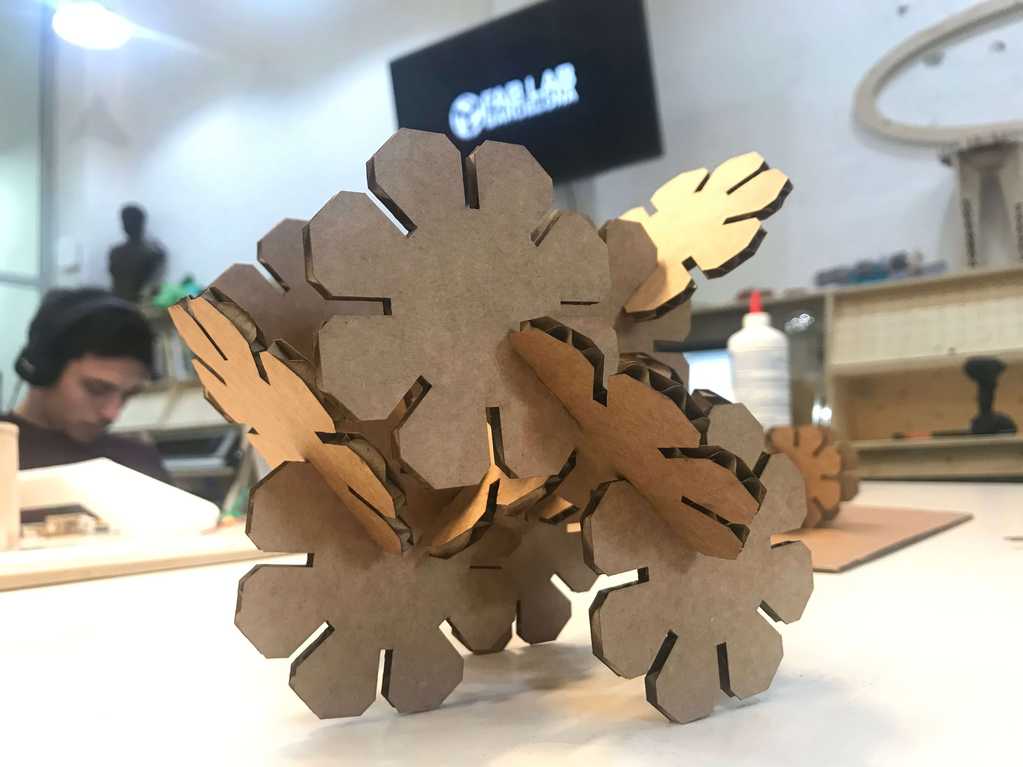
Cardboard Busta
I have to mention, that this assgnment was done back in 2016 and now in 2019 it has changed so there are updates needed to fulfill the new requirements. So I had to create a new strategy. I have checked few interesting examples as e.g.:this well not sure if this can be acceptable option, so I went for something for sure acceptable and I followed this example of ex fab academy student. It was using Rhino+Grasshopper, so I adjusted the gh definition how I wanted and also according the material I was using - cardboard 3mm thickness.
The definition is following these steps: We create a polygon which we explode in order to get the segments lines, on each of the line segments, we find the middle point. From points we set and orient the plane aligned to the center of the polygon. On each plane, we create a rectangle (these will be the fitting slots of material thickness). We subtract these rectangles from the original polygon. On each slot plane, we create a square (these are the chamfers). We subtract these squares to the resulted geometry. Then we get curves to cut off a wished single element. In Rhino we create our material with dimensions that we want to cut from. Next step is to create an array of the layout of the elements in our material. The last step is to bake it all!
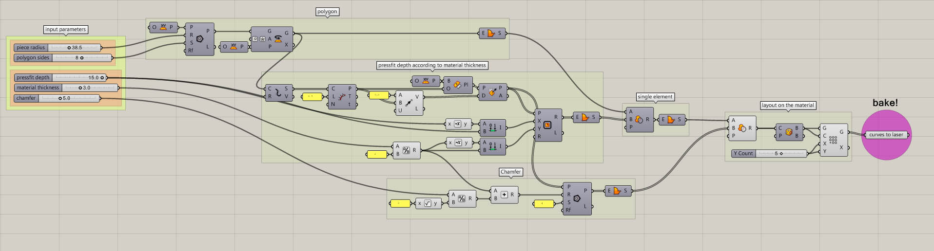
Grasshopper definition.
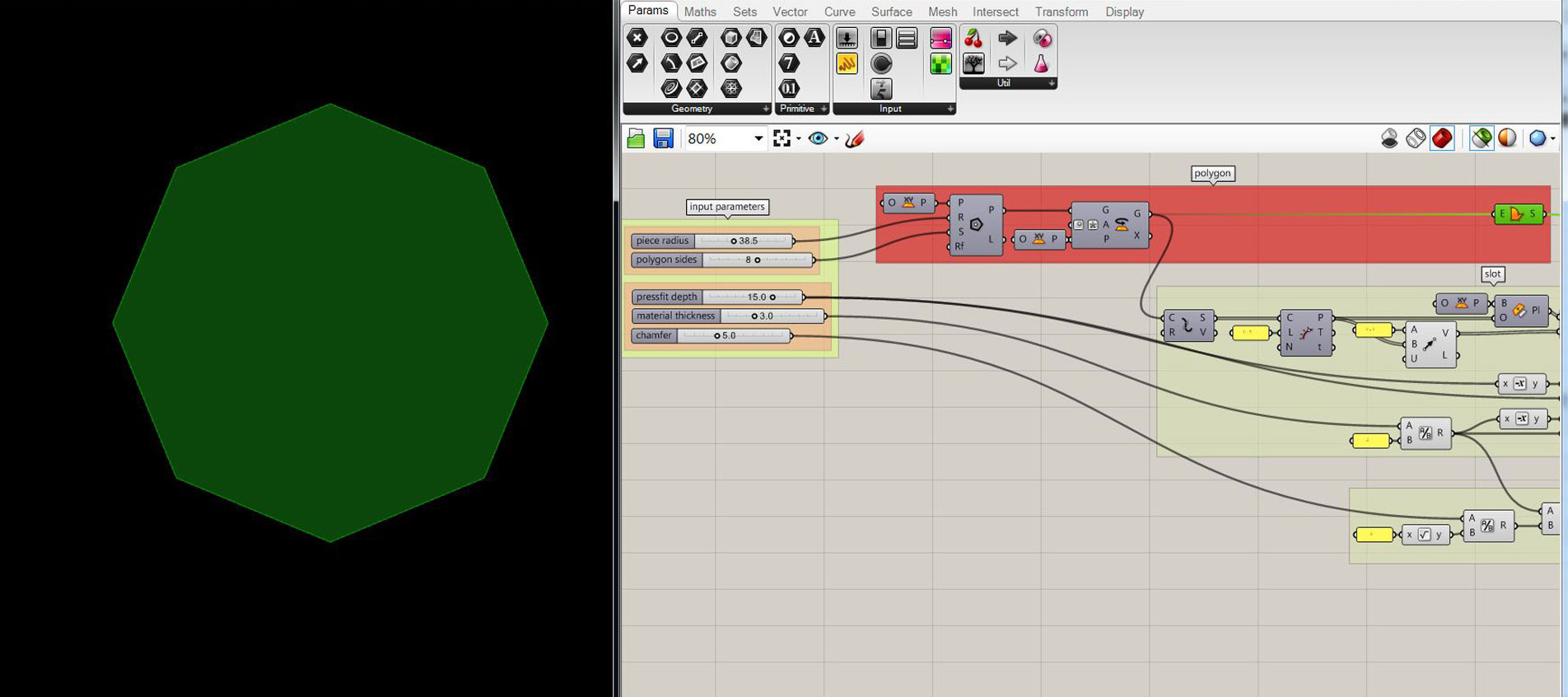
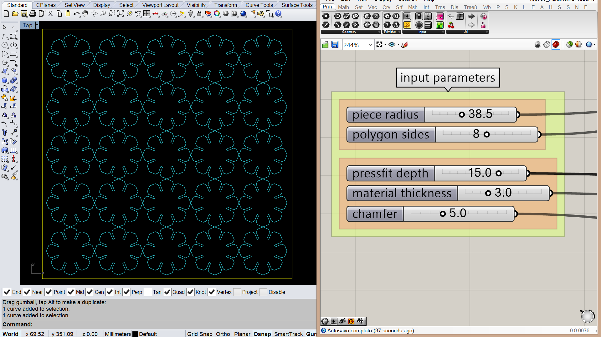
This part of the definition manages the number of polygon sides according to input parameters.

Pressfit depth of the fitting slot + the width of the slot (or the thickness of the material).

The length of the chamfer to make the fitting easier and of course, it affects the visual appearance of a single element piece.
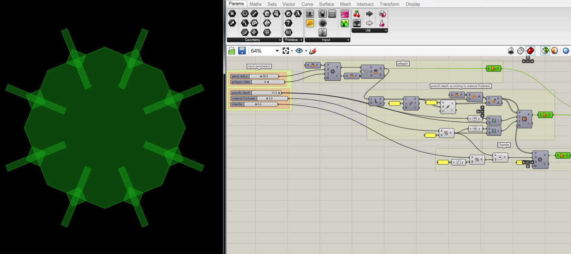
All parts together overlayed. Just to visualise whats happening...

This is the single element what we need to populate on our material to cut.
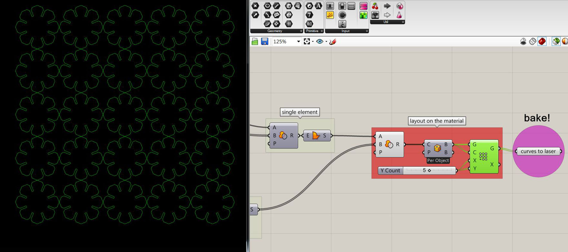
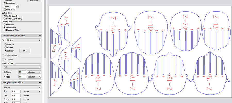
All pieces arranged on the material. You can decide how many pieces you want to have in array.
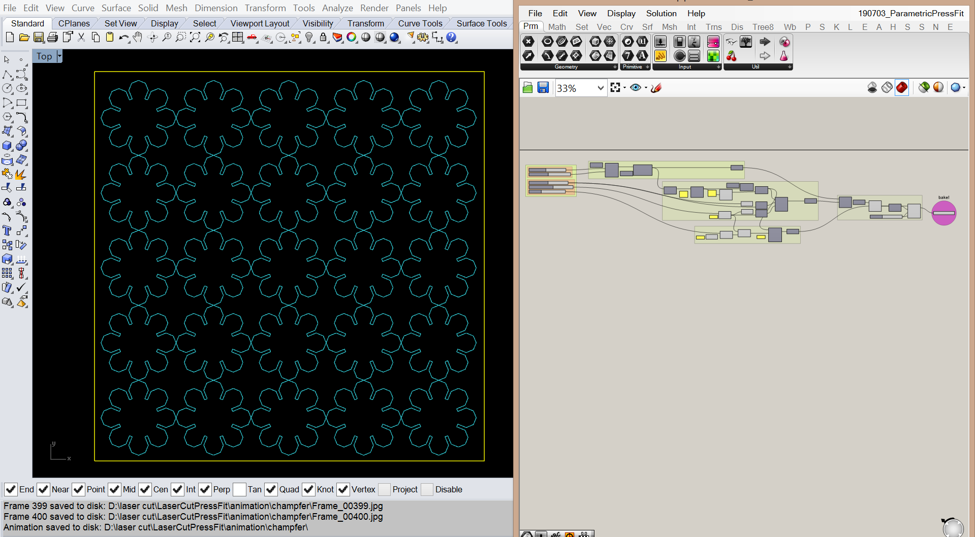
adjusted gh definition with elements divided into the material diensions.
those settings I decided to use for my design.
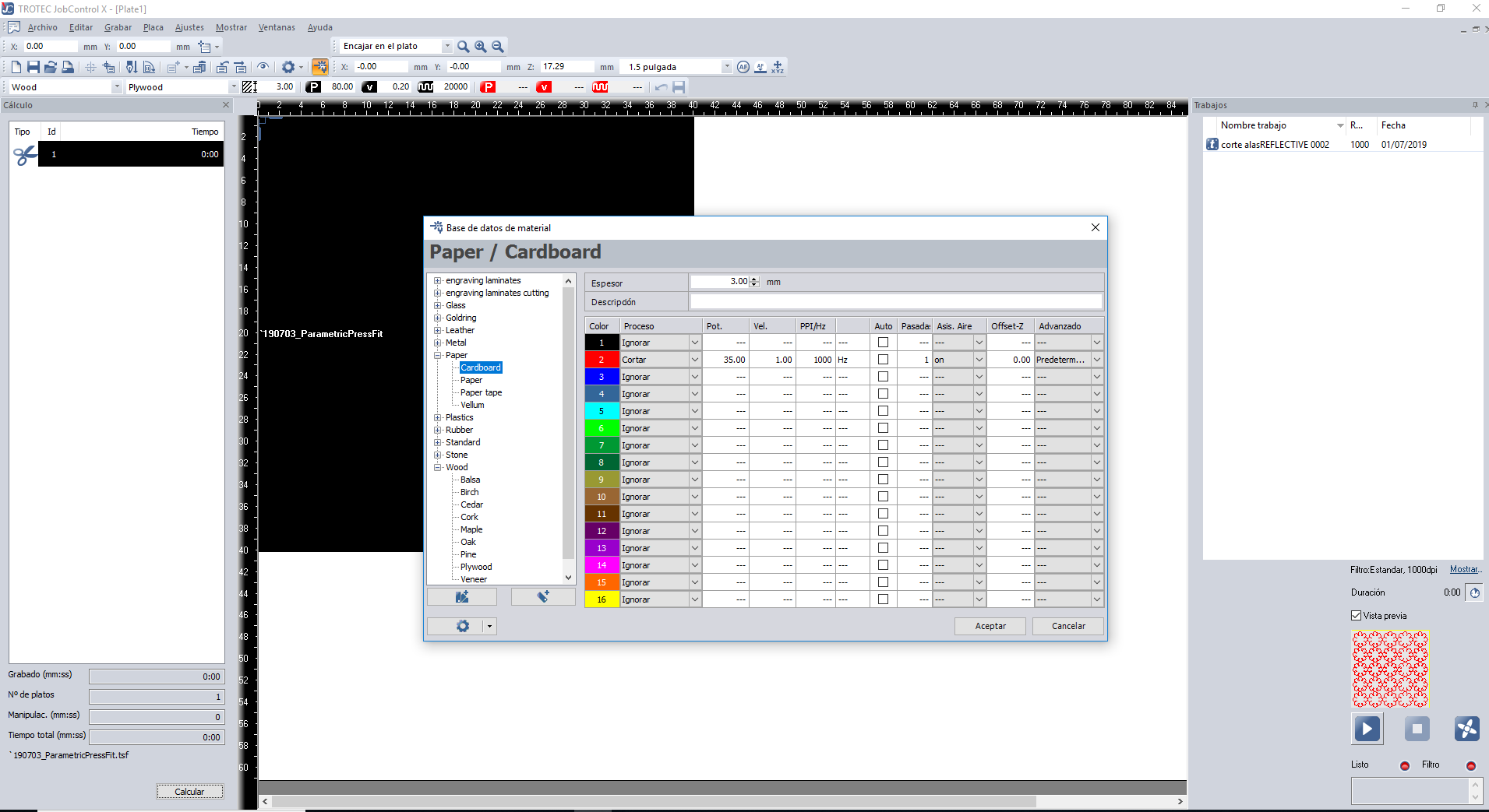
settings for lasercutting. I used TrotecSpeedy400.

Next...
vinyl cutting
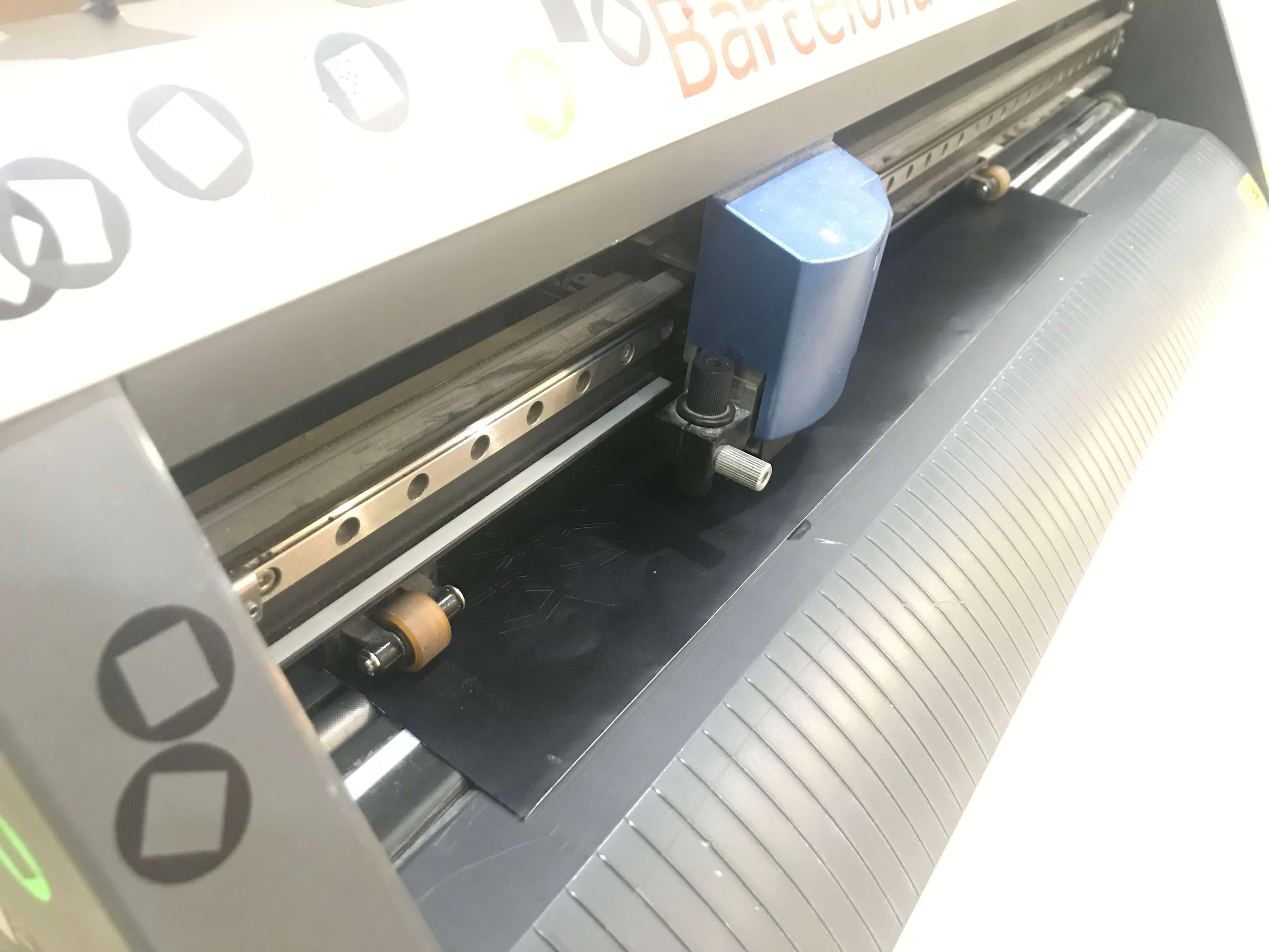
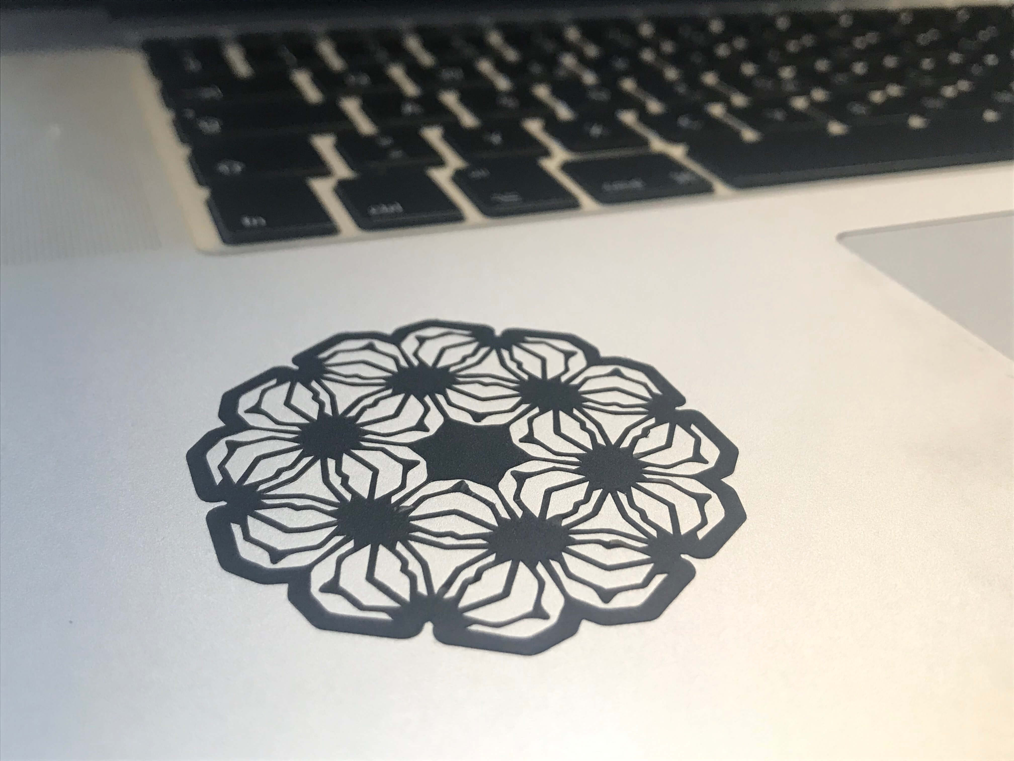
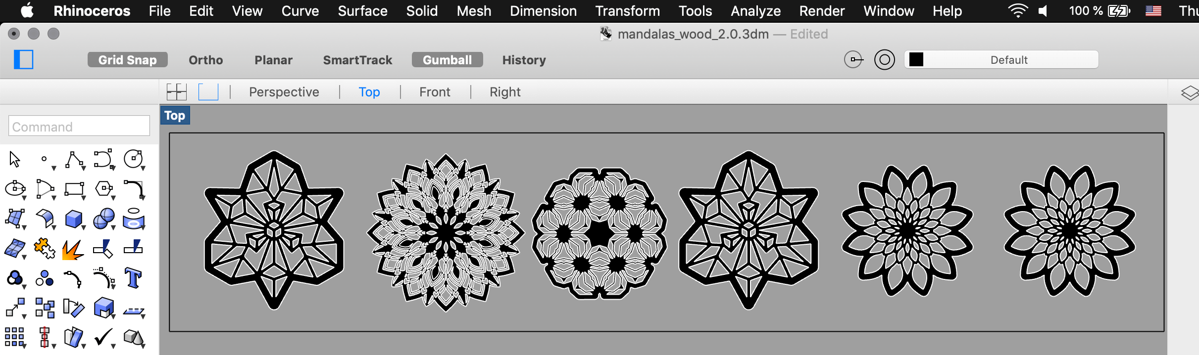
I used Roland GX-24 for the vinyl cutting. In the lab, we also have Cameo 3 Vinyl cutter. Since it has a really simple controller and the usage is pretty straight forward. I created my design in Rhino SW using 2D curves/vector strategies, array tool, mirroring, trimming...then I exported them as .ai and imported them into the CutStudio SW installed on the Lab computer. The first step was to find a piece of vinyl to use. Then turn on the machine, load into the material, clamp it, the machine automatically checks the dimensions of the piece. In my case it was a piece, not roll...you can preset those preferences. Then go to the SW and get the dimensions from the machine, import file. go to file/cut and the cutting process starts...just wait for the result.
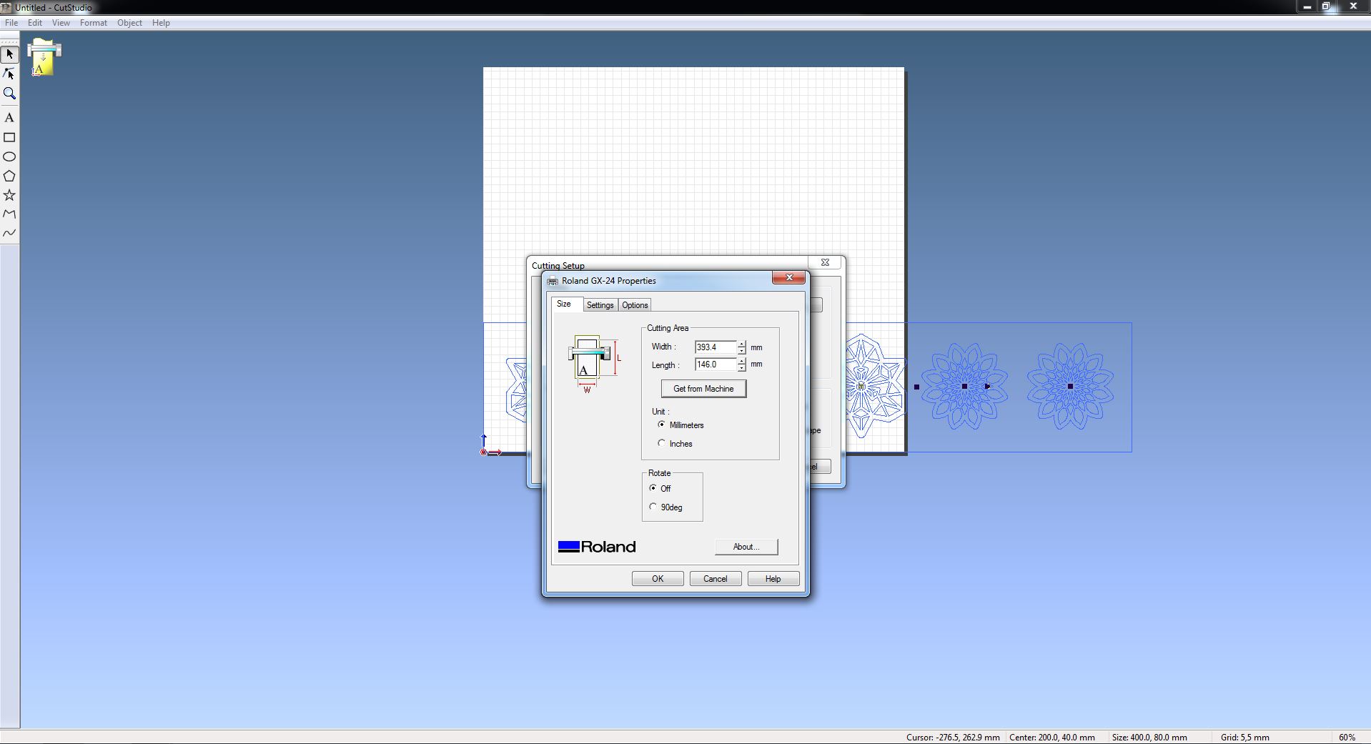

CutStudio interface. Settings used Blade: 1.0 Force: 80 gf Speed: 30cm/s